Experimental Investigation of Vertical
Connections in Precast Wall Panel under Shear
Load
R. Ahilan S. Anandhi
ME Student Assistant Professor Department of Civil Engineering Department of Civil Engineering SRM Easwari Engineering College, Ramapuram, Chennai,
Tamil Nadu, India
SRM Easwari Engineering College, Ramapuram, Chennai, Tamil Nadu, India
Dr. V Govindharajan
Chief Engineering Manager
L&T Construction Pvt. Ltd, Chennai-600089
Abstract
This Project deals with the experimental study and analysis of precast wall panel connections. The integrity of a precast system depends on connections more than the structural members itself. The connections between panels are the key factors which affects both the speed of erection and the overall integrity of the structure. The types connection proposed in this study is loop connection with trapezoid shear keys. The shear keys are used to increase the shear carrying capacity of the connections. The connection between the walls is called loop bars connection. Between the looping bars, one transverse bar is inserted as to ensure connectivity of all the looping bars. This connection produces a gap between the walls, which would then be filled with grouting material. The main objective of these experimental studies is to determine behaviour of loop bars connection under shear loading.
Keywords: Wall panel connections, vertical connection, grouting, loop bars, shear loading, transverse reinforcements ________________________________________________________________________________________________________
I. INTRODUCTION
General Introduction
Prefabricated concrete shear wall panels are used extensively in high rise construction. Precast concrete structural systems benefit from advantages, such as improved quality of construction, efficient use of materials, reduced construction time, and cost efficiency. In addition, precast concrete allows architects and engineers to perform more innovative designs than traditional cast-in-place concrete design.
One of the main concerns in precast concrete construction is the method by which the panels are connected. Connections must provide adequate strength, ductility and continuity in order to insure the integrity of the structure under various loading conditions. It is most important for a successful construction of precast reinforced concrete structures in terms of the structural behaviour. The main purpose of the structural connection is to transfer forces between the precast concrete elements through connections in order to obtain structural interaction once the system is loaded. The connections between panels are extremely important, since they affect both the speed of erection and the overall integrity of the structure. Therefore, the structural connections should design properly as the same for the precast.
The design of connections is one of the most important considerations in the structural design of a precast concrete structure. The purpose of a connection is to transfer load, restrain movement, and provide stability. Within any one connection, there may be several load transfers; each one must be designed for adequate strength and ductility and be appropriately detailed.
Connections in Precast Concrete
Connections in Reinforced Concrete wall panels
The reinforced concrete joints are usually subjected to shear, tension or flexure. The connections within reinforced concrete joints are usually secured by the continuity of the reinforcement that may be achieved by appropriate use of splicing of reinforcement. The connections are as follows
Lapping of bars with straight ends
Welding of bars or steel plates
Reinforcement grouted into apertures
Overlapping of reinforcement loops
Prestressing
Threaded or filled sleeving and
Threaded couplings.
Vertical wall to wall connection
The vertical joints are designed to transfer shear forces under lateral loads. The joint faces are indented to provide shear keys for shear transfer with increasing lateral loads. Beyond cracking of concrete, a strut-and-tie action is expected to develop. Overlapping reinforcing loops are provided along with shear keys to take up the horizontal component of the inclined compressive strut.
A continuous vertical bar is provided inside the overlapping loops from the adjacent units. The loops thus couples the adjacent panels. For sufficient out-of-plane support, a panel is adequately connected to the perpendicular panel through overlapping reinforcing loops with the vertical bar. The exterior wall panels along the shorter direction of the building, which constitute the primary shear walls to resist the lateral forces, are provided with six shear keys per storey height. In interior wall joints, reduced number of reinforcement loops are provided per storey height since the shear demand is less.
II. SCOPE
The scope of the work comprises an experimental study on the shear load carrying capacity of vertical joints between two adjacent precast wall panels.
The capacities of proposed vertical connections are to be tested for account.
The compressive strength of concrete in the joint and loop connection parameters.
Identify the contribution of each component used for the connections.
Comparisons studies on specimens with different loop connections
Estimate the strength due to Strut and tie action, anchorage bond strength and stress developed at the critical section.
III. OBJECTIVE
The main objectives of this project are:
To investigate failure mode of vertical connection under shear load.
To study the cracking resistance of joints with the vertical connections
To determine behaviour of loop bars connection under shear loading.
To examine the strut and tie actions of joints with shear key connections.
To determine the maximum shear stress the connection can take.
IV. LITERATURE DISCUSSION
Based on various literatures, it is that connections in precast wall panels, including shear walls, must be designed to transfer all design forces and moments.
The presence of shear keys in the horizontal connection enhances the shear capacity in comparison to the plain surface connection. The difference in the shear key configuration had an insignificant effect on the behaviour capacity of connection.
Table – 1 MIX PROPORTION
Cement Fine Aggregate Coarse Aggregate
383.3 kg/m³ 682 kg/m³ 1288kg/m³
1 1.78 3.36
V. DIMENSIONS OF PRECAST PANELS AND CONNECTION
The wall Panels dimensions are assumed as 0.6m height, 0.4m width and 0.1m thickness. Furthermore, connection of walls which is located in the gap between two panels is 0.3m height, 0.15m width and 0.1m thickness.
Connection parameters
The loop bar is provided with a diameter of 12 mm is used to connect the two panels.
The length of the bar is provided as development length which is 50 times the diameter.
The transverse reinforcement bars of same diameter are provided between the loops.
Shear keys of different shapes are provided to study the behavior of connection.
Fosroc Conbextra GP 2 is a ready mix dry power is used a grouting material to connect the panels.
Connection Types
Loop connection is an efficient form of reinforced concrete connection. It consists of the application of splicing the looped bars protruding from the respective precast concrete members. In a way it is reminiscent of a spirally reinforced concrete column if the loops are considered to act as stirrups. Three types of loop connections are considered and they are
Loop Connection Trapezoid Shear Keys (angle 45°).
1) The depth and length of the shear key are taken as 50mm and 100mm respectively. 2) The depth and length of the shear key are taken as 50mm and 100mm respectively.
3) The additional reinforcement is provided to improve ductility and to avoid failure due to tension.
Loop Connection with Trapezoid Shear Keys
1) Loop connection with trapezoid shear keys (angle 45°) and additional transverse reinforcements 2) Loop connection without shear keys.
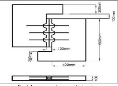
The Connection Configurations Are Shown In Figures 6.1 to 6.3.
Fig. 1: Loop connection trapezoid shear keys
VI. RESULTS AND DISCUSSIONS
Compressive Strength of Cylinder
Specimen: Cylinder
Dimensions: 150mm X 300mm Area of Cylinder: 176.7 X 10³ Mm2 Instrument Used: Demec Gauge
Table – 2
Compressive Strength Of Cylinder Load
(Kn)
DemecGauge Readings Avg Strain
Stress (Kn/Mm2) At Top At Bottom
0 0.525 0.425 0.475 0
10 0.492 0.390 0.441 0.000056
20 0.535 0.356 0.445 0.00011
30 0.500 0.362 0.431 0.00016
40 0.490 0.402 0.446 0.00022
50 0.468 0.365 0.416 0.00028
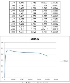
150 0.553 0.422 0.4875 0.00084
200 0.517 0.340 0.428 0.00113
250 0.479 0.253 0.366 0.00141
300 0.445 0.291 0.368 0.00169
350 0.485 0.353 0.419 0.00198
400 0.400 0.242 0.321 0.00226
450 0.486 0.245 0.365 0.00254
500 0.454 0.204 0.329 0.00282
550 0.422 0.209 0.315 0.00311
600 0.475 0.244 0.359 0.00339
650 0.368 0.115 0.2415 0.00367
700 0.333 -0.017 0.158 0.00396
Fig. 2: Stress Vs Strain Graph
Concrete Cube Testing
Grade of concrete : M35
Dimensions : 100mm x 100mm
Table – 3 3rd DAY TESTING
Sample Weight (Kg) Yield Load (kN) Strength (N/mm2)
1 2.469 221.6 22.16
2 2.579 176.24 17.62
3 2.576 224 22.4
Table – 4 7rd DAY TESTING
Sample Weight (Kg) Yield Load (kN) Strength (N/mm2)
1 2.422 364 36.4
2 2.468 252 25.2
3 2.382 172 17.2
Table – 5 28th DAY TESTING
Sample Weight (Kg) Yield Load (kN) Strength (N/mm2)
1 2.530 304 30.4
2 2.570 308 30.8
3 2.466 410 41
Split Tensile Test
SPECIMEN : Cylinder MATERIAL : Concrete
Table – 6 split Tensile Test
Sample Weight (Kg) Density Load (kN) Strength (N/mm2)
1 4.108 4108 110 3.52
2 4.146 4146 104 3.33
3 4.104 4104 100 3.2
Compressive Strength of Grouting Material
Specimen : Cube
Material : FosrocConbextra Gp2 Dimensions : 40mm X 40mm
Table – 7
Compressive Strength of Grouting Material Sample Load (KN) Strength (N/mm2)
1 109 68.125
2 55 34.38
3 126 78.75
Test Results of Non-Destructive test
Table – 8 3rd DAY TEST OF M
35 GRADE CONCRETE CUBE Sample Density (Kg/m3) Rh UPV (m/s)
1 2469 25.4 4785
2 2579 24.9 4785
3 2576 27.25 4673
Table – 9 7rd DAY TEST OF M
35 GRADE CONCRETE CUBE Sample Density (Kg/m3) Rh UPV (m/s)
1 2422 28.75 5155
2 2468 31.62 5155
3 2382 31.60 5025
Table – 10 7rd DAY TEST OF M
35 GRADE CONCRETE CUBE Sample Density (Kg/m3) Rh UPV (m/s)
1 2530 39.5 5855
2 2570 38.7 5654
3 2466 38.26 5575
Testing Of Panel with Vertical Connection
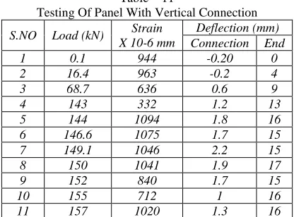
The wall panel is tested under Uniformly Distributed Load (UDL) conditions. The testing of panel is done with the help of hydraulic operated jack connected to load cell. The load is applied to the beam with the help of hydraulic jack and the data is recorded from the data acquisition system, which is attached with the load cell. One LVDT (Linear Variable Deflection Transformer) is placed at the center of the specimen and second LVDT is placed on end of panel. The value of deflection is obtained from LVDT.
Table – 11
Testing Of Panel With Vertical Connection
S.NO Load (kN) Strain X 10-6 mm
Deflection (mm) Connection End
1 0.1 944 -0.20 0
2 16.4 963 -0.2 4
3 68.7 636 0.6 9
4 143 332 1.2 13
5 144 1094 1.8 16
6 146.6 1075 1.7 15
7 149.1 1046 2.2 15
8 150 1041 1.9 17
9 152 840 1.7 15
10 155 712 1 16
12 161 945 2.1 15
13 162.7 914 1.6 15
14 164 1093 0.6 16
15 165 35406 1.7 16
16 170.2 35406 1.9 16
17 175 35406 2.1 16
18 181 35406 2.1 16
19 184 35406 1 16
20 185 35406 1.3 17
21 188.1 35406 1.4 18
22 190.1 35406 1.7 19
23 195 35406 1.3 20
24 195.2 35406 5 19
25 200 35406 5.8 2.1
26 200.8 35460 5.6 21
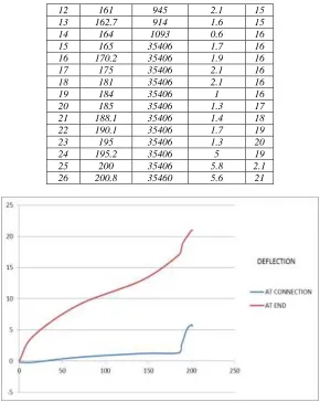
Fig. 3: Load Vs Deflection of Panel Test
VII. CONCLUSION
On applying loads up to 200 KN, it is observed that the connection provided for the panels are intact except for some micro cracks. On increasing loads above 200 KN it is observed that the cracks are formed in the panels while the connection still takes the load. So it can be concluded that the provided connection is more than adequate to resist shear load produced during earthquakes. The connection configurations can be used for practical purposes.
REFERENCES
[1] Is 456-2000 plain and reinforcement concrete- code of practice? [2] Is 10262-1982 recommended guidelines for concrete mix design?
[3] HaoJunbao, “Structural behaviour of precast components with loop connections”, National University of Singapore, 2004.
[4] IzniSyahrizal Ibrahim1, KhairulHazmanPadil, Hamid Mansoor, and Noor NabilahSarbini, “Ultimate Shear Capacity and Failure of Shear Key Connection In Precast Concrete Construction”, Malaysian Journal of Civil Engineering, 26(3):414-430, 2014.
[5] Ahmad BaharuddinAbd. Rahman And Ong HernYee , “Grout Filled Steel Pipe Integrated With Shear Key for Precast Concrete Connection” .
[6] Nabila Rossley, Farah Nora Aznieta Abdul Aziz, Heng Chiang Chew and NimaFarzadnia , “Behaviour of Vertical Loop Bar Connection in Precast Wall Subjected To Shear Load”, AENSI- Australian Journal of Basic and Applied Sciences, January 2014.
[7] Sami H. Rizkalla, “Multiple Shear Key Connections for Precast Shear Wall Panels”, PCI journal, March-April 1989. [8] H.R.Foerster, et al., “Behaviour and design of shear connectors”, January-February 1989.
[9] RaminVagheia, FarzadHejazia, Hafez Taheria, Mohd Saleh Jaafarb and Abang, “Performance of Precast Concrete wall to wall Connection”, IC BEE 2013- 5th International Conference on Chemical, Biological and Environmental Engineering, P.177-194.
[10] Bindurani.P, A. Meher Prasad, Amlan K. Sengupta, “Analysis of Precast Multistoreyed Building – A Case Study”, IJIRSET- International Journal of Innovative Research in Science, Engineering and Technology, ISSN:2347-6710, Vol-2, December 2013.
[11] Gheorghe Ciuhandu, ValeriuStoian, “Design of vertical joints in precast reinforced concrete shear walls”, 2015. [12] M.L.Lau, S.H.Rizkalla and K.A.Soudki, “Connections for precast load bearing shear wall panels”.
[13] In-Hwan Yang, Kyung-Cheol Kim, and Young-Joon Kim, “Shear Strength of Dry Joints in Precast Concrete Modules”.