e-ISSN: 2278-067X, p-ISSN: 2278-800X, www.ijerd.com Volume 7, Issue 12 (July 2013), PP. 18-24
Influence of Switching Elements on Harmonics and Power
Factor Improvement
1
A.Kumar,
2Dr.G.R.Gurumurthy
B N M Institute of Technology, BSK 2nd stage, Bangalore, India - 560070
Abstract:- Increasing demand for electrical energy by utilities has necessitated efficient utilization of available power. Most of the loads in the industry and domestic applications are inductive in nature causing a lagging power factor. This causes a reduction in the utilization of the power input. For the same power input the utilization can be improved by improving the power factor. Further the presence of harmonics results in poor quality of the power leading to losses. . In present days, solid state electronics control electric motors are frequently used for drive control (speed and torque). This can introduce harmonics in current and voltages. The general opinion among technologists is that improvement in power factor reduces losses in an electrical system. Although this is true in a general way, it is not so in systems which use switched electronic devices that can introduce large amount of harmonics [1].
The present work is aimed to study the effect of power factor correction on circuits consisting of power semiconductor switching. Boost convertor supplied from an unregulated supply was considered for the analysis of a static loading. The work also involved study of power factor improvement(PFI) for dynamic load. An automatic power factor controller was designed and implemented induction motor load. The controller was designed to sense the various parameters of the power and calculate the power factor. A rule-based table has been developed based on the power factor input. The controller can sense this power factor and automatically switch ON/OFF appropriate KVAR as per the programmed requirement. The results obtained are comparable with that reported in several previous work done.[1-6]
Keywords:- Power factor improvement, Harmonics, THD, APFC, Filters
I. INTRODUCTION
Quantum of Energy generation is one of the metric for the measurement of a Nation’s development. The requirement of energy is much more than the amount of power getting generated in developing countries like India. Under these circumstances Demand side management (DSM) is one of the methods to improve the utilization of energy. Most of the industrial and domestic loads are inductive in nature and hence the power factor of the loads are very poor. An improvement in the power factor results in availability of more active power for the same generated power. Power factor improvement is most commonly used in industrial units. Automatic power factor controllers (APFC) are equipped with semiconductor devices, switching of capacitor banks for the improvement of power factor. In present days, solid state electronics control for electric motors are frequently used for drive control (speed and torque). This can introduce harmonics in current and voltages. The general opinion among technologists is that improvement in power factor reduces losses in an electrical system. Although this is true in a general way, it is not so in systems which use switched electronic devices that can introduce large amount of harmonics.
a. Power factor:1. Concept of Power Factor
Power factor is defined as the ratio of active power to apparent power. i.e., PF = . It is also defined as a cosine of the angle between voltage and current vectors in an electric network in which voltage and current are sinusoidal parameters. i.e., PF = cos Φ, where Φ is the angle between voltage and current vector. A poor power factor requires more apparent power for the same amount of active power consumed. It also increases the current level of operation and thereby increases losses in the system. A poor power factor is generally the result of inductive loads such as induction motor, welding set etc,. The poor power factor can also be due to distortion in current waveform resulting from power electronic based converters like rectifier, inverter etc,. used in the system.
II. BENEFITS OF POWER FACTOR IMPROVEMENT
The benefits that can be achieved by applying the correct power factor correction are:
2. Extra power is available from the existing supply due to reduction of consumption in reactive KVA. 3. Reduced I2R losses in machines and hence efficiency increases.
4. Voltage regulation improves due to reduced voltage drop in long cables & long lines. 5. The current drawn for the same load is lesser hence KVA loading of the machines reduce.
The figure 1.1 shows the power triangle. Active power (kW)
Φ Reactive Power
Total power (kVAr)
(kVA)
Fig 1.1. Power triangle
III. POWER FACTOR IMPROVEMENT FOR INDUCTIVE LOADS
Power factor improvement is commonly adopted method for effective utilization of available power. The various advantages of improving power factor have been discussed earlier. The power factor improvement incorporates additional capacitive reactive power which compensates for the inductive reactive power of the load and thus improving power factor [1]. The vector diagram showing the improvement in power factor using capacitor bank is given in Fig.1.2
Ic
Reference Ic = capacitor compensation current
Φ2 Voltage I load1 = load current with pf=cosΦ1
Φ1 Iload2 = load current with pf=cosΦ2
ILoad2
ILoad1
Fig1.2: Vector showing power factor improvement using capacitor bank.
KVA saving by improving power factor from cos Φ1 to cos Φ2 can be obtained as given in the
expression below: saving in KVA = (KW / cos Φ2 ) - (KW / cos Φ1). For improvement of power factor in
large capacitive loads suitable inductors have to be used.
b. Harmonics:
Harmonics have existed for many years in the power lines of plants and factories. However only over the last decade they have turned into a major problem to normal operations. This is largely due to the proliferation of harmonic producing equipment and the increased sensitivity of certain types of equipment to harmonics. The effects of harmonics can often be serious - computer systems may fail to operate properly; capacitor banks, such as those used for power factor correction may fail prematurely (much before expected life). The presence of harmonics increases losses in the system.
IV. CONCEPT OF HARMONICS:
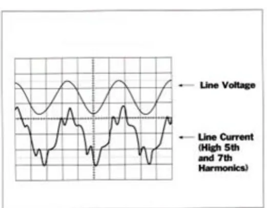
Harmonics are distortions to the voltage and current waveforms from their normal sinusoidal shape. At the power generating stations, a 50 Hertz (Hz) sine wave is generated and distributed to a large number of residential and industrial loads. Certain types of loads distort the 50Hz wave by injecting additional signals of various magnitudes and frequencies. These additional signals are also sinusoidal in shape but their frequencies are multiples of the original waves for example, 150, 250 and 350Hz. These waves are called harmonics.
Fig 1.3. Waveform showing a sample of distorted current waveform due to harmonics.
V. SOURCES OF HARMONICS:
The various sources of harmonics are discussed under:
1. Increase in use of Power converters which use controlled switching, such as rectifiers, inverters, and AC phase control systems has increased harmonics due to switching action.
2. Motors: Asymmetrical air gaps, slight irregularities in mounting axes can cause motors in equipment such as pumps, fans and compressors to produce harmonics.
3.APFC capacitors: Power Factor Correction Capacitors can magnify harmonics if not properly applied.
VI. PFI IN AN UNCONTROLLED RECTIFIER WITH BOOST CONVERTER a. Introduction and Design
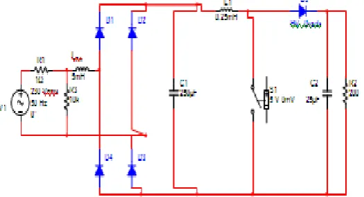
An uncontrolled single phase rectifier supplying a boost converter with duty cycle of 50% and 90% was considered for investigation. The basic circuit used is given in Fig 2.1. For the design of the rectifier a ripple factor of 1% was considered.
Considering the frequency of 50hz and CF = 250μF we get,
The ac input applied was 230v, 50Hz. The output of the rectifier was a DC of 325 V with 1% ripple. The boost converter was designed with a switch at 50% Duty cycle(D). Therefore the expected output voltage is Vo = VS /
( 1 –D) = 325 / 0.5 = 650V. Also the boost converter was designed with a switch at 90% Duty cycle(D). Therefore the expected output voltage is Vo = VS / ( 1 –D) = 325 / 0.1 = 3.25kV.
Fig 2.1 Uncontrolled rectifier with Boost converter.
phase angle between fundamental components of voltages and current was considered as the power factor angle. Using the actual current waveform, the power losses were determined.
b. Results:
Initial investigations were carried out for duty cycle of 50% with and without any harmonic filter. Subsequently, simulations were carried out with duty cycle as 90% as per the circuit in Fig 2.2.
Fig 2.2 Uncontrolled rectifier with Boost converter with series reactors
The results obtained are tabulated below. Table 2.1 shows the results obtained by considering a series reactor. Losses were calculated as Pin - Po
Table 2.1. Boost converter with series reactor in series with the supply (DC = 50%) Sl
No. VDC
(V) Lse
mH
pf Pin watt Po watt
ITHD
in %
Loss (w)
1 632 0 0.71 5500 3300 40.3 2200 2 632 0.1 0.71 5500 3400 40.1 2100 3 632 0.5 0.72 5800 3480 40.6 2320 4 632 1 0.74 6000 3600 39.1 2400 5 632 3 0.83 7500 4700 39 2800 6 632 5 0.91 8200 5000 38.9 3200 7 632 7 0.96 8200 4880 38.6 3320
Table 2.2 shows the results obtained by considering a 90% duty cycle. Losses were calculated as Pin - Po
Table 2.2. Boost converter with series reactor filter in series with the supply (DC = 90%) Sl
no.
VDC (V) Lse
mH
pf Pin watt Po watt ITHD
in %
Loss (w)
1 3300 0 0.91 16150 6460 7.3 9690 2 3300 0.1 0.93 16150 6460 7.1 9690 3 3300 0.5 0.94 17423 6960 7.15 10440 4 3300 1 0.98 18000 7200 6.7 10800 5 3300 3 0.99 22500 9000 6.5 13500 6 3300 5 0.993 24300 9720 6 14580 7 3300 7 0.997 24670 9870 5.8 14800
c. Discussions:
VII. POWER FACTOR IMPROVEMENT EFFECT ON A DYNAMIC LOAD a. Load description:
The load selected for the investigation of power factor improvement effect on dynamic load is a 3-phase Induction motor with name plate details as below:
NAME PLATE DETAILS:
POWER OUTPUT =2.2KW, 3HP, VOLTAGE=415V, CURRENT=4.8A, EFFICIENCY=79% CONNECTION TYPE: DELTA, FULL LOAD PF = 0.7, N = 1440 RPM
b. Reactive KVAR requirement for APFC:
The FL output of the motor is 2700w and at 0.72pf. The desired power factor was fixed for the APFC case at 0.99.
We know that the kVAR required for improvement is given by:
kVAR = P ( tanΦ1 - tanΦ2 ) where P = active power of the load. Φ1 = initial power factor angle Φ2 = required power factor angle
kVAR = 2.700 ( tan(cosˉ1 0.72) – tan (cosˉ1 0.99)) = 2.5 kVAR
The capacitor bank is to be connected in star.
Therefore, Vph = VL / √3 = 415 / √3 = 239.6V.
ICph = (kVAR * 1000) / ( 3* Vph) = 2500 / (3*239.6) = 3.47A
Thus, XCph = (Vph / ICph ) = 239.6 / 3.47 = 69Ω.
Therefore Cph = 1 / ( 2*π* 50 * 69) = 46µF.
It was decided to use the required rating using 4 stages of capacitors.
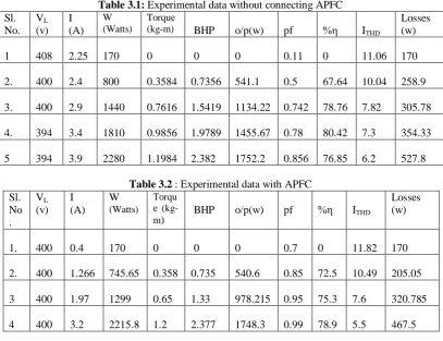
The experiment was conducted after the calibration of the APFC under 2 cases. Case 1 was performed without the APFC connected to get the base data which are as tabulated in Table3.1. The in case 2 the APFC was connected and the data were obtained as tabulated in table 3.2.
Table 3.1: Experimental data without connecting APFC Sl.
No. VL
(v) I (A)
W (Watts)
Torque
(kg-m) BHP o/p(w) pf %η ITHD
Losses (w)
1 408 2.25 170 0 0 0 0.11 0 11.06 170
2. 400 2.4 800 0.3584 0.7356 541.1 0.5 67.64 10.04 258.9
3. 400 2.9 1440 0.7616 1.5419 1134.22 0.742 78.76 7.82 305.78
4. 394 3.4 1810 0.9856 1.9789 1455.67 0.78 80.42 7.3 354.33
5 394 3.9 2280 1.1984 2.382 1752.2 0.856 76.85 6.2 527.8
Table 3.2 : Experimental data with APFC Sl.
No .
VL
(v) I (A)
W
(Watts) Torqu e
(kg-m) BHP o/p(w) pf %η ITHD
Losses (w)
1. 400 0.4 170 0 0 0 0.7 0 11.82 170
2. 400 1.266 745.65 0.358 0.735 540.6 0.85 72.5 10.49 205.05
3 400 1.97 1299 0.65 1.33 978.215 0.95 75.3 7.6 320.785
The images of the APFC and its connection to the circuit is shown in Fig 3.1
3.1 APFC with circuit connection for pf correction of an Induction motor
c. Discussions:
Variation of power factor and its effect have been analysed with incorporation of dynamic loads. A 3-phase IM was selected as dynamic load. A 3-3-phase Automatic Power Factor Controller (APFC) has been designed and constructed for studying the on-load performance. Also, the APFC has been calibrated using accurate reading meters (Voltmeter, Ammeters and Watt meters). The inaccuracy indications of APFC are within ±2%.
The results of experimental investigations using above APFC set up show that the power factor can be improved up to 0.99. It was also observed that the trend with respect to the behaviour of THD and losses with variation of power factor is same with and without APFC. With increase in power factor THD is decreasing. Also, losses are increasing with increase in power factor & load.
VIII CONCLUSION
An uncontrolled boost converter supplied from uncontrolled rectified supply was simulated with and without power factor improving capacitors. The effect of improving the power factor on the THD was studied and the filters were incorporated to reduce the level of THD. In the second phase an 3-phase APFC was designed and implemented for a dynamic load, a 3-phase IM. The APFC was calibrated and designed with very high precision components to ensure proper operation. The machine was experimentally analyzed with and without the APFC.
The performance verification of the simulation and hardware implementation has shown that:-
1. In case of circuits involving power electronic switching the even harmonic components, in particular the 2nd harmonic component, was predominant.
2. The use of appropriate filters with the circuit at output and input results in reduction of THD in input current. 3. Passive filters have limitations and are not sufficient to reduce the THD below the IEEE-519 standards. Active filters may be used in that case.
4. Results of experimental investigation using APFC shows that the power factor can be improved up to 0.99. 5. Increase in power factor in general decreases the THD.
6. At constant load, with increase in power factor, the losses are reduced.
7. Increase in power factor increases the losses. This is mainly due to increase in load current.
8. The trend with respect to the behavior of THD and losses with variation of power factor is same with and without APFC. However, the magnitude of THD is considerably reduced with increase in load.
ACKNOWLEDGMENT
The authors of the paper would like to acknowledge the Management of BNMIT for providing the necessary research facilities.
REFERENCES
[1] Francis.M.Fernandez, P.S.Chandramohanan Nair, “Influence of power factor compensating capacitor on estimation of harmonic distortion”, 9th
International conference on Electrical power quality and utilization” Barcelona, 9-11 October 2007.
[2] IEEE standard 519-1992 Recommended Practices and Requirements for Harmonic control in Electric Power systems 1993.
[3] Lorenzo Cividino, “Power factor, Harmonic Distortion; Causes, Effects and Consideration “, IEEE 1992 Page 506-514
[5] Fatih Basçiftçi and Ömer Faruk Hatay, “Microcontroller-controlled reactive power measurement and saving circuit design for residences and small scale enterprises”, Scientific research and essays Vol 5(16), pp 2312 – 2317, 18-Aug-2010.
[6] K.Chatterjee, B.G.Fernandes and Gopal.K.Dubey, “An Instantaneous Reactive VA Compensator and Harmonic Suppressor System” IEEE Transactions on Power Electronics, Vol 14, No.2, 1999, pp 381-392.
[7] Nicola Locci, Carlo Muscas, Sara Sulis, “On the measurement of power quality indexes for Harmonic distortion in the presence of capacitors”, IMTC – 2005 – Instrumentation and Measurement Technology Conference Ottawa, Canada, pp. Vol 3 1600-1605,May 2005.
[8] “Operational Amplifiers and Linear IC” by Ramanand Gaekwad, PHI [9] “Linear Integrated Circuits” by Roy Choudary, New Age Publications
[10] Renesas Electronics America Inc “ User manual for YMCRPRX62T – Microcontroller”. [11] “SPICE for circuits and Electronics”, Muhammed H.Rashid, PHI, 2002