Published online March 30, 2015 (http://www.sciencepublishinggroup.com/j/acis) doi: 10.11648/j.acis.s.2015030201.15
ISSN: 2328-5583 (Print); ISSN: 2328-5591 (Online)
Hybrid method for ciphering colored image
Salman Abd Kadum, Ali Abdul Azeez Mohammad Baker
Computer Systems Techniques, Al Furat Al Wast University, Al Najaf Technical Institute, Al Najaf, Iraq.
Email address:
[email protected] (S. A. Kadum), [email protected] (A. A. A. M. Baker)
To cite this article:
Salman Abd Kadum, Ali Abdul Azeez Mohammad Baker. Hybrid method for Ciphering Colored Image. Automation, Control and Intelligent Systems. Special Issue: Artificial Nano Sensory System. Vol. 3, No. 2-1, 2015, pp. 22-34. doi: 10.11648/j.acis.s.2015030201.15
Abstract:
Security has more and more importance in current era especially in the organizations where information is more critical and more effective, so there are many methods that will be used in keeping information secure and safety like steganography, cryptography, barcode, password, and biometrics. different techniques will be used to protect image data from unauthorized access, In this paper a hybrid method will be proposed for ciphering secure image by translating information from original RGB image to YCbCr format then using public key algorithm after normalized pixels values to insure that will be within public and prevent keys region after that the Modified Arnold Transform, Generalized Fibonacci Transform, and Fibonacci-Lucas Transform will be applied on each ciphered band from YCbCr image respectively.Keywords:
Cryptography, Ciphering, Deciphering, Color image, Public Key, Private Key, Arnold Transform, Fibonacci Transform, Fibonacci-Lucas Transform1. Introduction
Cryptography is the science of hiding information, or is a fundamental tool for the protection of sensitive information. Encryption is a way of talking to someone while other people are listening, but such that the other people cannot understand what you are saying. It can also be used to protect data in storage. The goal of cryptography is to make data unreadable by unwanted persons. According to the key that will be used in ciphering algorithm, Cryptography algorithms are divided into two types, symmetric key and public-key (asymmetric) algorithms. Symmetric algorithms are used the same key in both ciphering and deciphering algorithms. While Public-key encryption algorithms used a pair of keys, the first key is used in encryption information that will be sent to a receiver
which is named (public) or the second key who owns the corresponding private key which is used in decryption the information. Image encryption techniques are used to overcome the problem of secure transmission for both images and text over the electronic media by using the suitable cryptographic algorithms.
1.1. Public Key Cryptography
Public key algorithm is a powerful method for ciphering information, and the strength of this algorithm depends on the strength of the public and private keys. As we know that every person who wants to send secret information by using unsecured channel must used a suitable way to protect this information, one of the most important protection method which is public key algorithm.
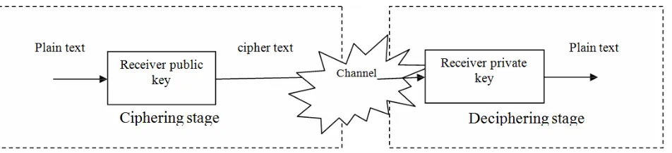
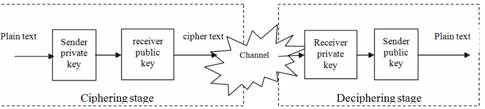
Figure (2). Signature encryption method.
Every person has two related keys (public and private), and if any person want to send secrete message to another person, he must used the public key of the received person to cipher the message and then send it by using any transform media, after that the received person must be deciphering the message to extract the information, and this operation done by using receiver private key as illustrated in figure (1), in some cases sender ciphering the message by using sender private key firstly then receiver public key and this state called the signature, so the receiver deciphering the message by using receiver private key firstly, then sender public key to extract information as illustrated in figure(2).
The two keys of any person are related and they created from primary numbers by using special method as follows:
Selecting two big prime numbers (p, q), and big number (e) randomly.
Calculatingθ
( ) (
n = − × −p 1) (
q 1 ,)
n= ×p q. Calculatingd GCD(
(
p 1 ,) (
q 1)
)
( )
n 1e
θ
− − × +
= .
Constructing public key (e, n), and private key (d, n). For example if person1 wants to construct his keys, firstly he choosesp=23,q=17,e=15.
( ) (
n 23 1) (
17 1)
352,n 23 17 391θ = − × − = = × =
(
22,16)
352 1 705 4715 15
GCD
d= × + = =
Then the public key of person1 is (15, 391), and the private key of person1 is (47, 391).
For ciphering any plain text by using public key algorithm the equation (1) will be used as follows:
( )
(
)
moder r number
C = number n (1)
Where
(
er n, r)
is the receiver public key.For example if any person wants to send message (HI) to person1 with above keys then,
( )
72,( )
73ASCII H = ASCII I =
( ) ( )
1572 mod 391 81
C H = =
( ) ( )
1573 mod 391 279
C H = =
Therefore the person sends the message 81, 279 to person1.
For deciphering any cipher text by using public key algorithm the equation (2) will be used as follows:
( )
(
)
mod ,dr r number
P = number n (2)
Where (dr, nr) is the receiver private key.
For the above cipher text that received by person1, he will extract plain text by applying equation (2) as follows:
( )81
( )
8147mod 391 72P = = =H
( )
( )
47
81 279 mod 391 73
P = = =I
Plain text is
( )
HI1.2. Arnold Transform
It is a transform 2 2
:T T
Γ →
[
]
' ' 2 1 mod 1 1 x x N y y = (3)
Where ' '
{
}
, , , 0,1, 2,... 1
x y x y∈ N− , and N is the size of an
original squared image.
A new image will be produced when all points in the original image are ciphered by equation (1). The Arnold transform change the position of each pixel in original image but the value of this pixel stay with same original value, this transform is simple but powerful which is very much easy in spatial domain.
The security level of the encrypted image becomes danger when it is encrypted by using the basic Arnold transform as it depend on a single 2x2 array so, to enhance the security level of the encrypted image the basic Arnold transform is modified as follows:
[
]
' ' 1 mod 1 1k k x
x N y y + =
(4)
Where x y x y, , ,' '∈
{
0,1, 2,...N−1}
, N is the size of a digital squared image, and k={
0,1, 2, 3, ...}
by an unauthorized user) will be increased.
For k = 1, equation (4) is same as the original Arnold transform of equation (1).
1.3. Fibonacci Transform
This is a special case of the basic Arnold transform, the equation of the transform is:
[
]
' ' 1 1 mod 1 0 x x N y y = (5)
Generally, the Fibonacci sequence Fn, is a sequence of
integer numbers that given by equation (6):
1 2 0 0 1 1 n n n n F n
F− F− otherwise
= = = + (6)
By applying equation (6) the Fibonacci series constitutes the numbers:
0, 1, 1, 2, 3, 5, 8, 13, 21, 34, 55, 89, 144, 233 …
It can be easily seen that a 2x2 matrix formed by any four consecutive terms of the Fibonacci Numbers is a matrix and can be considered as an image scrambler. A generalized Fibonacci Transform can be defined as a mapping Γ :T 2 → T 2 such that:
[
]
' 1 ' 2 2 mod i i i iF F x
x
N
F F y
y + + + =
(7)
Where, x, y, x', y' ∈ {0, 1, 2 … N −1}, Fi is the ith term of the Fibonacci Series. And N is the zero size of a digital square image.
1.4. Lucas Series
Lucas series is a special case of Fibonacci series can be defined as follows:
1 2 2 0 1 1 n n n n F n
L− L− otherwise
= = = + (8)
By applying equation (8) the Lucas series constitutes the numbers:
2, 1, 3, 4, 7, 11, 18, 29, 47, 76, 123, 199, 322, 521 …
Unlike the Fibonacci series, the terms of the Lucas series does not form a periodic map and cannot be used for image encryption but by combining the terms of the N Fibonacci and Lucas series, a series of new periodic maps will be formed which can be used for image scrambling.
1.5. Fibonacci- Lucas Transform
The equation of this transform is:
[
]
' 1 1 ' 1 mod i i iF F x
x
N
L L y
y + + =
(9)
Where, x, y, x', y'∈ {0, 1, 2 … N −1}, Fi is the ith term of the F12 series, Liis the ith term of the Lucas series, and N is the size of a digital squared image.
Continuing in this way we can form an infinitely many transforms and just like the Modified Arnold and Fibonacci Transforms, all of these matrices will be periodic in nature with a maximum possible periodicity of N2-1.
2. The Proposed System
The proposed system consist of two stages, the first stage for encryption information and the second one for decryption, each one of these stages consist of many steps. The encryption steps will be illustrated in figures (3), which are:
Translate image into YCbCr format and separating colored image into three grayscale image, each one of them represent one band like y, Cb, Cr.
Applying normalization process for all pixels in each band according to the key value.
Ciphering each pixel in first grayscale image (y band) by using receiver public key.
Ciphering each pixel in second grayscale image (Cb band) by using receiver public key and sender private key.
Ciphering each pixel in third grayscale image (Cr band) by using received public key.
Scrambling all pixels in first band by using Arnold transform
Scrambling all pixels in second band by using Fibonacci transform.
Scrambling all pixels in third band by using Fibonacci-Lucas transform
Reconstructing colored image.
Scrambling all pixels in colored by using new Arnold transform.
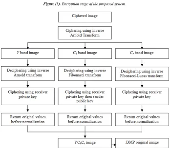
While the decryption steps illustrated in figure (4), which are:
Applying inverse Arnold transform on colored image. Separating ciphered image into three grayscale image (bands).
Applying inverse Arnold transform on first band. Applying inverse Fibonacci transform on second band. Applying inverse Fibonacci-Lucas transform on third band.
Deciphering each pixel in first grayscale image by using receiver private key.
Deciphering each pixel in second grayscale image by using receiver private key and sender public key. Deciphering each pixel in third grayscale image by using received private key.
Return original values before normalization. Reconstructing YCbCrimage.
Figure (3). Encryption stage of the proposed system.
Figure (4). Decryption steps of the proposed system.
Each step in the proposed system will be illustrated with an example, by using the following keys:
receiver public key (3,187),
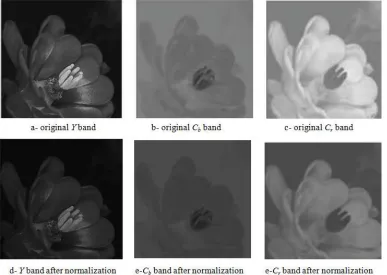
With the following bands for part of colored image as illustrated in figure (5).
Figure (5). Bands for part of colored image.
3. First Stage
This stage for encryption information contains many steps as follow:
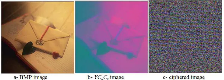
3.1. Translating to YCbCr Image
Figure (6). Translating to YCbCr image.
(YCbCr) image will be created from BMP image by using equation (10) as illustrated in figure (6) and (7):
16 0.299 0.587 0.114 128 0.168 0.331 0.5 128 0.5 0.418 0.081 b
r
Y red
C green
C blue
= + − − ×
− −
(10)
To calculate values of all pixels in each band from red, green, and blue bands, Equation (10) will be applied as follows:
For y band: 16+(0.299×red+0.587×green+0.114×blue). For Cb band: 128+(-0.168×red- 0.331×green+0.5×blue). For Cr band: 128+(0.5×red- 0.418×green-0.081×blue).
The results of applying these states will be applied in figure (7).
Figure (7). YCbCr image values.
3.2. Normalization
Normalization process is an important step to prepare image pixels for ciphering because we cannot apply modulo of (133) on 256 values without loose information, so all values must be less than (133) to insure information retrieve, these process applied on all bands according to value of (n) in the key. The y band will be encrypted by key (3, 187) so all pixels in y band must have values between 0 and 186, in the same way blue band will be encrypted with key (3, 187) so all pixels in Cr band must have values between 0 and 186, while the Cb band will be encrypted firstly by key (3, 187) so all pixels in y band must have values between 0 and 186, after that the ciphered pixels in Cb band will be ciphered by
key (59, 133) so all pixels in ciphered Cr band must have values between 0 and 132.
For y band: 133×186/255= 97, 140×186/255=102, and so on for other values. For Cr band: 47×132/255= 24, 182×132/255=94, and so on for other values.
And for Cb band: the first normalized process is 203×186/255=148, 143×186/255=104.
The second normalized process will be done after ciphering with key (3,187). The pixels value of colored image in figure (7) will be normalized as illustrated in figure (8).
The results of applying this step will be illustrated in figure (9).
Figure (9). Results of normalization step.
3.3. Public Key Encryption
As illustrated in the proposed system block diagram, each band will be ciphered with different key or keys, so this step will be separated into three states.
Figure (10). Encryption Y image.
( ) ( )
397 97 mod187 113
C = =
Figure (11). Results after applying key (3, 187) on Y image.
3.3.1. Y Band
In this band, the cipher used received public key for encryption all pixels in this band by applying equation (1) as
illustrated in figure (10) as well as in calculating the new ciphered values for supposed example with key (3, 187) as shown in figure (11).
3.3.2. Cb Band
In this band, the cipher used received public key and sender private key for encryption all pixels in this band by applying equation (1) with additional normalization process as illustrated in figure (12) as well as in calculating the new ciphered values for supposed example with keys (3, 187) and (59, 133) as shown in figure (13).
Figure (12). Encryption Cb image.
C(97) = (148)3mod 187 = 147 then normalized all values to cipher with key (59, 133)
(
132)
147 76
255
× =
( ) ( )
5976 76 mod133 76
Figure (13). Results ciphering Cb image.
3.3.3. Cr Band
In this band, the cipher used sender private key for encryption all pixels in this band by applying equation (1) as illustrated in figure (14) as well as in calculating the new ciphered values for supposed example with key (59, 133) as shown in figure (15).
Figure (14). Encryption Cr image.
Figure (15). Results after applying key (3, 187) on Cr image.
3.3.4. Scrambling Pixels in Each Band
As illustrated in proposed system block diagram, each band will be scrambled with specific transform, so this step will be separated into three states.
3.3.4.1. Y Band
Figure (16). Scrambling Y image.
In this band, the cipher used Arnold transform for scrambling all pixels by applying equation (4) as illustrated in figure (16) as well as in calculating the new ciphered values for supposed example as shown in figure (17).
[
]
( )
[
]
'
'
'
'
6 5 0
mod 3 0, 0 ,
1 1 0
6 5 0 2,1
mod 3
1 1 1
x y
x y
= =
= =
Figure (17). Results after scrambling Y image.
3.3.4.2. Cb Band
In this band, the cipher used Fibonacci transform for scrambling all pixels in this band by applying equation (7) as illustrated in figure (18) as well as in calculating the new ciphered values for supposed example as shown in figure (19).
Figure (18). Scrambling Cb image.
[
]
( )
[
]
( )
'
'
'
'
8 13 0
mod 3 0, 0 , 21 34 0
8 13 0
mod 3 1,1 21 34 1
x y
x y
= =
= =
Figure (19). Results after scrambling Cb image.
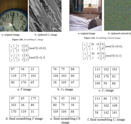
3.3.4.2. Cr Band
In this band, the cipher used Fibonacci-Lucas transform for scrambling all pixels in this band by applying equation (9) as illustrated in figure (20) as well as in calculating the new ciphered values for supposed example as shown in figure (21).
Figure (20). Scrambling Cr image.
[
]
( )
[
]
( )
'
'
'
'
1 1 0
mod 3 0, 0 ,
2 1 0
1 1 0
mod 3 1,1
2 1 1
x y
x y
= =
= =
Figure (21). Results after scrambling Cr image
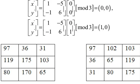
3.3.5. Scrambling All Pixels in Colored Image
In this step, the cipher used Arnold transform for scrambling all pixels in this band by applying equation (4) as illustrated in figure (22) as well as in calculating the new ciphered values for supposed example as shown in figure (23).
Figure (22). Scrambling Colored Image.
[
]
( )
[
]
( )
'
'
'
'
20 19 0
mod 3 0, 0 ,
1 1 0
20 19 0
mod 3 1,1
1 1 1
x y
x y
= =
= =
Figure (23). Scrambling colored image.
3.4. Second Stage
The input for this stage is the final ciphered image that
3.4.1. Applying Inverse Arnold Transform
In this step, the inverse Arnold transform will be applied in colored image as illustrated in figure (24).
Figure (24). Applying inverse Arnold transform on colored image.
The inverse Arnold transform can be illustrated in figure (25) by using equation below:
[
]
( )
[
]
( )
'
'
'
'
1 19 0
mod 3 0, 0 , 1 20 0
1 19 0
mod 3 2, 2 1 20 1
x y
x y
−
= =
−
−
= =
−
Figure (25). Applying inverse Arnold transform on colored image.
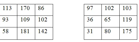
3.4.2. Return Pixels in Each Band to Its State before Scrambling
As illustrated in proposed system block diagram, each band will be decryption with specific inverse transform, so this step will be separated into three states.
3.4.2.1. Y Band
In this band, the decipher used inverse Arnold transform for return all pixels in this band to its past original state before scrambling as illustrated in figure (26).
Figure (26). Applying inverse Arnold transform on Y image.
Calculating values before scrambling in Y band for supposed example will be shown in follows and in figure (27).
[
]
( )
[
]
( )
'
'
'
'
1 5 0
mod 3 0, 0 ,
1 6 0
1 5 0
mod 3 1, 0
1 6 1
x y
x y
−
= =
−
−
= =
−
Figure (27). Applying inverse Arnold transform on Y image.
3.4.2.2. Cb Band
Figure (28). Applying inverse Fibonacci transform on Cb image.
Calculating values before scrambling in Cb band for supposed example will be shown in follows and in figure (29).
[
]
( )
[
]
( )
'
'
'
'
34 13 0
mod 3 0, 0 , 21 8 0
34 13 0
mod 3 1, 0 21 8 1
x y
x y
−
= =
−
−
= =
−
Figure (29). Applying inverse Fibonacci transform on Cb image.
3.4.2.3. Cr Band
In this band, the decipher used inverse Fibonacci-Lucas transform for return all pixels in this band to its past original state before scrambling as illustrated in figure (30).
Figure (30). Applying inverse Fibonacci-Lucas transform on Cr image.
Calculating values before scrambling in Cr band for supposed example will be shown in follows and in figure (31).
[
]
( )
[
]
( )
'
'
'
'
1 1 0
mod 3 0, 0 ,
2 1 0
1 1 0
mod 3 1, 2
2 1 1
x y
x y
−
= =
−
−
= =
−
Figure (31). Applying inverse Fibonacci-Lucas transform on Cr image.
3.4.3. Public Key Decryption
As illustrated in proposed system block diagram, each band will be deciphered with different key or keys, so this step will be separated into three states.
3.4.3.1 Y Band
In this band, the decipher used received private key for decryption all pixels in this band by applying equation (2) as illustrated in figure (32) as well as in calculating the new ciphered values for supposed example with key (107, 187) as shown in figure (33).
Figure (32). Decryption Y image.
( )113
( )
113 107mod187 113P = =
Figure (33). Results after applying key (107, 187) on Y image.
3.4.3.2. Cb Band
Figure (34). Decryption Cb image.
by applying equation (2) with additional inverse normalization process as illustrated in figure (34) as well as in calculating the new deciphered values for supposed example with keys (107, 187) and (11, 133) as shown in figure (35).
( ) ( )
1176 76 mod133 76
P = = then normalized all values to cipher with key (11, 133)
(
255)
76 147
132
× =
( ) ( )
107147 147 mod187 76
P = =
Figure (35). Results deciphering Cb image.
3.4.3.3. Cr Band
In this band, the decipher used sender public key for decryption all pixels in this band by applying equation (2) as illustrated in figure (36) as well as in calculating the new ciphered values for supposed example with key (107, 187) as shown in figure (37).
Figure (36). Decryption Cr image.
( ) ( )
107113 113 mod187 97
P = =
Figure (37). Results after applying key (107, 187) on Cr image.
3.4.4. Return Original Values before Normalization
In this step inverse normalized ratio will be applied to each pixel in each band as follows:
For y band: pixel value×255/186, for Cr band: pixel value×255/132, and for
Cb band: pixel value×255/186. this process results will be illustrated in figure (38).
illustrated in figure (39).
Figure (39). Translating YCbCr image into BMP image.
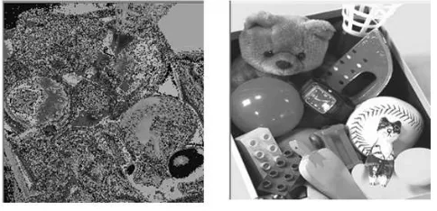
4. Results
After applying the proposed system on colored image, the f o l l o w i n g results will be founded.
Figure (40). Result (1) of the proposed system.
Figure (42). Result (3) of the proposed system
4. Conclusion
From the above discussions and results we conclude that: Scrambling image pixel is a powerful tool in ciphering image and it make image unreadable and unproductive, but scrambling methods must have long randomness cycle to avoid repeated values of new position for all pixels in original image.
Public key encryption changes the pixels value in image in fashion that make the image can be predictive with huge amount of noise, so this method cannot be used alone.
Normalization process is an important step to make information space identical to key space without losing information that damage image.
References
[1] Linhua Zhang , Xiaofeng Liao , Xuebing Wang " An Image Encryption Approach Based on Chaotic Maps", .elsevier , China, 2004.
[2] Kwok-Wo Wong, Bernie Sin-Hung Kwok, and Wing-Shing Law " A Fast Image Encryption Scheme based on Chaotic Standard Map", HONG KONG, 2006.
[3] Abdullah Sharaf Alghamdi, and Hanif Ullah "A Secure Iris Image Encryption Technique Using Bio-Chaotic Algorithm", IJCNS, 2010.
[4] Minati Mishra, Priyadarsini Mishra, M.C. Adhikary and Sunit Kumar," Image Encryption Using Fibonacci-Lucas Transformation", IJCIS, India, 2012.
[5] Rajinder Kaur, Er.Kanwalprit Singh " Image Encryption Techniques: A Selected Review", IOSR-JCE, India, 2013. [6] Quist-Aphetsi Kester " Image Encryption Based on the RGB
PIXEL Transposition and Shuffling" I. J. Computer Network and Information Security, 2013.
Biography
Dr. Salman Abd Kadum, Ph. D., Ms.C. Technical Education Foundation, Najaf Technical Institute, Najaf, IRAQ. He received B.Sc. in Physics sciences (1983) from Baghdad university, High Deploma in computer science (1988) from training & research institute, Baghdad, Iraq, M.Sc. in computer sciences (1998) from Gajah Mada university, Indonesia, and Ph. D. in computer science its also from Gajah Mada University, Indonesia (2004), worked as a lecturer as long time and a head of computer system in Najaf Technical Institute for two years, he is also a master of computer center for two years, and he is also as lecturer for eight years and a head of software engineering in Al-Imam Jaafar Alsadeq university for five years, he has many published papers. His researches interests are in image processing, and signal processing.