Abstract—Conformance testing is a way to determine if a developed system satisfies the requirements of a specification. As recently a CAN based standard for communication interface for DC fast charging is developed, it requires conformance testing to ensure the safety and proper operation. This paper exploits the use of TTCN-3 for this CAN based conformance testing and attention is focused on the implementation of TTCN-3. Two computers are used for communication via CAN. One computer is working as a tester and the other is working as a system under test.
Index Terms—Controller area network, conformance testing, TTCN-3, SGSF-064-1.
I. INTRODUCTION
When electric vehicle (EV) was invented in the mid-19th century, it was preferred means for transportation because it provided a level of comforts and ease of operation compared with the internal combustion engines. However, now in the 21st century, EVs are gaining more attention for its environmental friendliness such as low carbon emission and improved fuel efficiency from major automobile makers and environmental-minded consumers. Last year, in the U.S. alone, 96,000 plug-in EVs were sold which represent 0.6% of the total market of 16.5 million vehicles and 81% of increase compared to the previous year. Despite of record breaking sale of EVs, there remain several issues that make potential buyers hesitate to get it. They might include long charging time, short range of driving, heavy battery, and insufficient number of charging stations. In addition to them, some issues such as environmental friendliness of electric vehicle (EV) are also raised in [1].
Unlike gasoline or diesel powered vehicles, charging EV meets high level of safety requirement because of high power flow. Charging can be done either in AC or DC. AC charging is usually slow while DC is targeted to fast charging around 30 minutes. In support of these types of charging, IEC has made standards for the connector known as IEC 62196.
Competing for charging standards is still ongoing worldwide and it is no exception in Korea. As a major car import country, Korea supports various standards in the electric vehicle market now. The SAE DC Combo charging standard adopted by most European and US automakers including BMW, Volkswagen and GM and the CHAdeMO developed by Japanese companies such as Toyota and Nissan are available. In addition to these, AC fast charging by Renault is also recognized as a standard in Korea.
Manuscript received April 20, 2014; revised July 10, 2014.
The authors are with the Myongji University, Yongin, 449-728, Korea (e-mail: [email protected], [email protected], [email protected], [email protected], [email protected]).
Smart Grid Standardization Forum (SGSF) Korea has developed communication protocol between electric vehicle and conductive DC charger known as SGSF-064-1 to support EV from Korean automobile makers such as Hyundai and Kia. SGSF-064-1 is quite similar to CHAdeMO [2]. Since EV market is emerging anytime, it is imperative to develop conformance testing method for this standard to ensure the safety and the proper operation of the electric vehicle chargers.
The protocol, SGSF-064-1, for the communication of charger and EV is based on CAN. Control area network (CAN) is a serial bus network use to connect devices for real time control applications. It allows automotive components to communicate on a single or dual-wire networked data bus up to 1Mbps. We use CAN protocol for the communication of two computers using TTCN-3.
The Testing and Test Control Notation Version 3 (TTCN-3) is a testing language used to test variety of application domains and types of testing. It was invented in 2000, since that it was used in industry, research, international projects and academia. It is developed and maintained by the European Telecommunication Standards Institute (ETSI). Also it is a standardized testing technology.
This paper is divided as follow. Section II and Section III are about the CAN communication protocol and conformance testing, respectively. In Section IV a brief description of TTCN-3 is given. Section V describes the simulation and results. And last section is reserved for conclusion and future work.
II. OVERVIEW OF CANCOMMUNICATION
CAN is a serial data communication protocol invented by German BOSCH Corporation in the early 80s to realize the data exchange between numerous controllers and measuring instruments in modem automobile. It is a multi-master bus, the communication medium can be a double stranded wire, coaxial cable or optical fiber with data rate up to 1Mb/s. CAN communication protocol encodes the data and uses 8 bytes to transfer data. The transmission of data is fast enough to be used in real-time processing [3].
CAN communication uses two transmission lines to transfer data. One is the high transmission line CANH and the other is low transmission line CANL with their respective ground voltages VCANH and VCANL. CAN transfers message in the form of a frame.
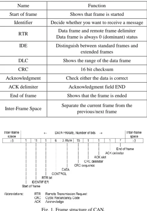
The frame is divided into several parts including all the information about the frame. Parts of frame with their functionality are shown in Table I.
Each part of frame has assigned some space in the form of bits. The division of data bits is shown in Fig. 1.
CAN Based Conformance Testing Using TTCN-3
TABLEI:FUNCTIONALITY OF DIFFERENT PARTS OF FRAME
Name Function
Start of frame Shows that frame is started
Identifier Decide whether you want to receive a message
RTR Data frame and remote frame delimiter Data frame is always 0 (dominant) status
IDE Distinguish between standard frames and extended frames
DLC Shows the range of the data frame
CRC 16 bit checksum
Acknowledgment Check either the data is correct
ACK delimiter Acknowledgment field END
End of frame Shows that the frame is ended
Inter-Frame Space Separate the current frame from the previous/next frame
Fig. 1. Frame structure of CAN.
When CAN communication is used to communicate two devices or machines, most of the devices cannot be connected directly. For communication, an interface or device is needed to work as an adapter to encode/decode the data. In our case we used two computers to communicate using CAN communication.
Fig. 2. Serial to CAN converter.
It is not possible to connect two computers using CAN directly. Mostly serial communication process is used for sending and receiving data to computers. A serial to CAN device as shown in Fig. 2 is used for the communication of two computers, which works as a bridge between two computers.
III. CONFORMANCE TESTING
Conformance testing is to confirm if an implementation faithfully meets the requisites of a standard or designation. Namely, it is a way to ascertain that standard predicated is implemented in the products.
A conformance testing includes standard or designation procedure for testing. There are many types of testing including performance testing, robustness testing, deportment
testing, functions and interoperability. The implemented protocol must follow the standard for proper synchronization and the process done opportunely.
In SGSF-064-1 several testing items have been discussed [2]. There are some cases where conformance testing should be done to ensure that the charging process will not be affected. The chargers provided by different charging stations must be tested before using them. So before connecting it to an electric vehicle, we check the charger by connecting it to a tester which performed as vehicle to confirm it that the charger is working fine and meet the standard requirements.
A. Testing Items in SGSF-064-1
We have developed several test cases for the testing items described in SGSF-064-1. There are five test cases discussed in the standards which are described below:
Start of normal charging
Fault occurred at charger/vehicle side Charging ended using stop button Unlock charging connector End of normal charging
When the charging connector is locked in to vehicle, it should be confirmed that the charger and electric vehicle are connected and are communicating properly so the charging process can begin. During the charging process if any abnormal behavior detected from any side, the charging process terminated immediately in order to avoid any damage.
During the charging of vehicle, user can use stop button to terminate the charging any time. If user presses stop button, charging process will be terminated. Then the charger and vehicle communicate to insure that the charging process is finished properly and the connector is ready to disconnect. Before finishing the communication if the connector is unlocked, it may cause damage to connector or vehicle.
TABLEII:TEST CASE FOR NORMAL ENDING
Normal end of charging
Pass
Fail
Inconclusive SGSF-064-1
Expected Results
Receive signal (#631.0.6=1) in 1 second which indicates that charging process is terminated
Receive signal (#631.0.5=0) in 1 second which indicates that charging connector is unlocked
Receive a signal which confirms that the controller power is OFF CAN Communication ended
Test Procedure
Send signal (#639.0.7=0, 639.4~7=0) for charge termination request
After 5 seconds send signal (#639.0.3=0) to OFF main contactor CAN Communication ended
When the vehicle is charged properly, it shows the signal of fully charged. Before giving the signal of being fully charged, the vehicle checks the inner current that should be less than 5A which implies that vehicle is fully charged. After that the charging connector will be unlocked, the charger check the voltage must be less than 60V which implies that the charging connector is disconnected properly.
during the whole charging process. If the charger does not respond properly, the charging process may disturb. So before using the charger to charge electric vehicles, it should be tested using a device which can perform as vehicle. Communication protocol used between charger and vehicle is control area network (CAN). Out of these testing items, we performed experiment for one testing item (Normal end of charging) whose test cases are shown in Table II. Fig. 3 shows the flow diagram of normal end charging.
Fig. 3. Flow diagram of normal end of charging.
B. Conformance Testing Using CAN Communication
To perform experiment we took two computers. One is considered as charger and the other as vehicle. The two computers communicate just like charger and vehicle using CAN communication. We made code in TTCN-3 for vehicle which is working as a tester and C# code for charger which is working as system under test (SUT). As two computers cannot communicate directly using CAN, so serial to CAN device shown in Fig. 2 is used for communication.
IV. INTRODUCTION TO TTCN-3[4],[5]
The Testing and Test Control Notation Version 3 (TTCN-3) is a standardized testing method developed by the European Telecommunication Standards Institute (ETSI). As the name implies its aim is to test or certify various domains of applications. TTCN-3 has been utilized in industry, research, international project and academia since its standardization in 2000.
This programming language looks as a regular programming language but it is much easier. It concentrates on testing and it provides a lot of functions and tools to make it fully compatibles with black-box testing, like dynamic test configuration, timer handling, procedure-based communication, the concept of verdicts, verdict resolution,
etc.
TTCN-3 is independent programming language; it can work on different operating systems and platforms. It also offers two options to run either compiling or interpreting. TTCN-3 provides standardized interfaces for test control for encoding and decoding of data.
Testing and deploying different types of applications like protocol and service testing, testing of embedded, communication-based, and distributed systems are the most important applications for TTCN-3. Many applications like SIP, WiMAX and DSRC use TTCN, also it is used within the automotive industry.
The architecture of TTCN-3 comprises entities that it is responsible to get abstract specifications in TTCN-3 into concrete implementations of test systems. TTCN-3 is used to specify tests in an abstract way but a test system is required to execute these tasks. TTCN has two interfaces for the interaction between the different test entities and the TTCN-3 Executable, TTCN-3 Control Interface (TCI) and TTC-3 Runtime Interface (TRI). Fig. 4 clarifies the architecture of TTCN-3. We will explain SA and PA later.
Fig. 4. The architecture of TTCN-3.
As a testing language, TTCN-3 provides quickness, ease and accuracy for testing various systems. Because internationally standardized, it would be the best solution to test our system, on the other hand, to try test a system like EV charger we need to deploy an algorithm for each case like, start of charge and end of charge. TTCN-3 provides test cases which can be used to test each case separately, in addition, to it, TTCN-3 has timer handling method. Timer handling is substantial for our testing because the project has two important things, response and the response time.
V. SIMULATION AND RESULTS
In the simulation we have two sides. First one is the testing system that was written by TTCN-3. The other is the system under the test (SUT) representing EV charger simulation written by C#. Fig. 5 shows the system structure.
In this simulation we experimented the normal end-of-charge by the vehicle flow control algorithm. This algorithm includes two requests from the tester and three responses from the EV charger. First tester sends stop charging request and wait 4 seconds for the charging termination from the SUT. After 4 seconds it sends Vehicle Main Contactor off and waits 1 second for the power off response. And within 1 second another replay must come from the SUT to acknowledge the ending of charging. Fig. 6 shows the results we obtained after execution.
TTCN will pass verdict if the requests come successfully and in the time, or it will return fail if there is any error.
The application runs as Client/Server network, in which tester acts as a server while SUT is a client.
A. Timer
TTCN-3 contains timer to measure the time spent in each step. In our applications there are unequal distribution of the time required, some steps take longer time to execute while others take shorter time. Each step requires specific time to complete. Fig. 7 shows the timers.
If the response reaches before the end of Timer, then the execution will move to the next step until it reaches the last one, then tester sets verdict pass.
In the case when the response reaches after the end of the timer, the tester interrupts the execution and sets verdict fail. Fig. 8 shows the error appeared when there is an error in timer in the last step.
Fig. 6. Normal end-of-charge by the vehicle flow control.
Fig. 7. Using timers in TTCN-3.
Fig. 8. A simple error in the TTCN-3 timer.
B. Connection [6]
adapter (SA).
Fig. 9. Connections and identifiers for TTCN-3.
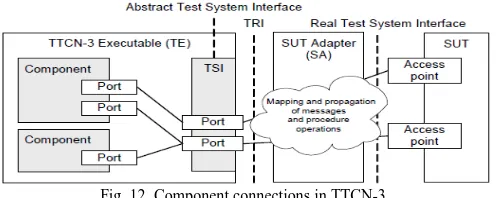
There are two operations in TTCN-3 communications, first is the message-based communication and the other is procedure-based communication. If the connection is message from TE to the SUT, then the SA receives a command from the TE. The command requests delivering message from the TE to a specific access point in the SUT, while, if the connection is procedure. The SA receives a command from the TE to call or to reply to a function in specific access point in the SUT. Fig. 9 shows the connection elements.
The function of service access point (SAP) is to pass the message to the SUT or to invoke a specific method in the SUT and then get the return value.
The connection manager (CM) is used to take care of the connection. When the connection is opened the CM handles all the details of the protocol(s). Test case configures CMs by using one of the ports that is control port. Each message received from control port considers as a control message.
C. Sending Message or Calling Procedure
As mentioned above, there are two communication operations to send message or to call function in SUT. TTCN-3 executes command like send(), then TE calls the TRI operation triSend(), and then SA passes the request to the CM, In the end, CM sends the requests to the SUT during this operation, SA sends the message without waiting for the completed of the request.
D. CM Interface
CM system Interface (CSI) provides the link between the SA and CMs' services. It has three operation modes, system, class and connection. The system mode SA can shut down or start the CM system. In the class mode, SA can add a new class, this is done by passing the interface object to the system. These objects are used to call class by CM system. In the connection mode the SA sends operation from TRI to the CM system.
To make the connection between the CM system components and CM class possible, CM class interface (CCI) is used. CCI has two operations, connection level operation and encoding operation.
E. Variables Types [6]
TTCN-3 has a different behavior with the types, unlike
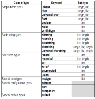
most programming languages. In TTCN-3, you can drive a sub-type or change the size of types. It has some base types as shown in Fig. 10.
In Fig. 10, “range” means that programmer can make sub-type from this type, while “list” indicates programmer can assign a limited values for this type. “Length” denotes that programmer can resize this type. String, integer and float have infinity size. Also TTCN-3 has a nice special feature that makes you define a variable as a record so that, this variable can has no value, in other words, and the value for this variable can be omitted.
Fig. 10. Basic variables types in TTCN-3.
F. Templates
TTCN-3 can consider as a data-structured language. It is data structure which can define a specific data types. It is used to match between received data and the template sets. In the sending, template specifies one value to send, in other hand, the template can be parameterized selectively. We can use parameterized to choose which value that specifies the value for the template.
G. Functions, Test Cases and External Functions
There are three parameter types in functions in TTCN-3: input, output and input-output. They can have return value too. It is possible for functions in TTCN-3 to run only on one component, in this case functions will have the privilege to use ports, timers and variables of the component.
In order to run a testing procedure, test case is used. Test case is special function that runs in a component and has value of the total verdict of the test. It is also limited by a single kind of system interface. The execution of this fiction is written in the control part. Test cases can also call a specific type of function which their implementation is outside the TTCN-3, these are called external functions. External functions are executed in the TRI operation which in turn orders platform adapter to call the required function.
H. Encoding and Decoding
sending data between two components, in this case internal representation is used. In the second case when the exchanging of data is done between component and SUT, there is something must be done. TTCN-3 tool has a codec which is responsible to encode data into some transfer syntax, after the encoding. The tool passes the data to the SA through TE. The codecs calls interface to do encoding and decoding, this interface is specified in the standard [T3TCI: s. 7.3.2 TCI-CD][4]. The received message from SUT also must be decode into some format.
I. Modules
Module is the compilation unit (CU) for TTCN-3. It contains the whole code of application. Module has one or more test cases. The modules consist of two parts, definition and control parts. These parts are not mandatory, it is possible to write just one part and omit the others. The definition contains the variables, data structure and other top level-definitions. It is also possible to import definitions from other modules. Control part contains the executable part consisting of test case execution. Sometimes it is possible to neglect the control part when there is another way for execution in TTCN-3 tools.
TTCN-3 modules can have more than one parameter, these parameters can be passed to control part or definition part during the execution time.
J. Components and Ports [6]
Component is an entity including ports, variables and timers. Port is very important for the component because the component can send and receive data to the SUT through the ports. They are also the means to interact with other components. Fig. 11 clarifies the component structure in TTCN-3.
Fig. 11. Component structure for TTCN-3.
When the component connects with other components their ports connect with each other. When the component connects to the SUT, the port of the component must map to one of the test system interface port. Fig. 12 shows the connection between component and other objects.
Fig. 12. Component connections in TTCN-3.
There is a queue in the port so that when new message comes it is firstly put in the queue, the queue is modeled as a FIFO queue.
K. Verdict
During the test case execution time, each component that is available must have an object of the verdict. This object has a value which can be set using setverdict and also it can be read by using getvedict. Four deferent values can set to the verdict, none, pass, inconclusive and fail. The sequence of these values are not arbitrary, in other words, none is the best value for verdict while fail is the worst. Verdict cannot change from low to high value, but it is possible to get lower value. For example, if verdict is set as pass then it can be change to inconclusive but it is impossible to set as none.
L. Platform Adaption [6]
Normally when there is any missing in messages, timer will handle it. However as the timer has different implementations in different platforms, sometimes we need different timer notation. Timer notation must be supplied by the test system developer.
VI. CONCLUSION AND FUTURE WORK
In this paper the conformance testing items of SGSF-064-1 have been discussed. We did simulation for one of the testing item normal end charging. We use two computers to communicate using CAN communication. The purpose of this simulation was to test a system (charger) which is connected with a testing device (computer) using TTCN-3. Results obtained after the simulation which shows the process of testing the system. In case of any error or verdict fails, it will be shown in the graph or results obtained.
In the future we will do the simulation of all the testing items of SGSF-064-1 using TTCN-3. We will adopt the same method of using two computers connected via CAN for the testing items.
ACKNOWLEDGEMENT
This work was supported by the Electric Power Public Tasks Evaluation and Planning Center (ETEP) grant funded by the Korea government Ministry of Trade, Industry and Energy (No. 1-2011-0-052)
REFERENCES
[1] O. Zehner, “Unclean at any speed,” IEEE Spectrum, vol. 50, no. 7, pp. 40-45, 2013.
[2] Smart Grid Standardization Forum, “Communication protocol between electric vehicle and conductive DC charger,” SGSF-064-1, 2014.
[3] R. Li, J. F. Wu, H. Y. Wang, and G. C. Li, “Design method of CAN bus network communication structure for electric vehicles,” IEEE Trans.
on Strategic Technology, pp. 326-329, Oct. 2010.
[4] C. Willcock, T. Deiß, S. Tobies, S. Keil, F. Engler, S. Schulz, and A. Wiles, An Introduction to TTCN-3, 2nd Edition, 2011.
[5] Elvior. TestCast Professional. [Online]. Available: http://www.elvior.com/testcast/ttcn-3-professional.
Tayyab Wahab Awan was born in Peshawar, Pakistan. He got the BS degree in telecommunication engineering in 2012 from National University of Computer and Emerging Sciences in Peshawar, Pakistan. He entered a master course in information and communication engineering in Myongji University in 2013.
His current research interests include vehicle to grid, Kalman filtering, particle filtering and multi-viewpoint tracking.
Ahmed Mahdi Abed was born in Baghdad, Iraq. He
is a candidate for masterdegreein communication and information engineering in Myongji Univ., South Korea. He got the BS degree in computer engineering from University of Baghdad, Iraq, 2013. Currently he works on electric vehicle research.
Intaek Kim was born in Seoul, Korea. He received the
BS and the MS degrees in electronics engineering from Seoul National University in Seoul, Korea in 1984 and 1986 respectively. He obtained the Ph.D. degree in electrical engineering from Georgia Institute of Technology in Atlanta, Georgia, USA in 1992.
He worked for Goldstar Central Research Lab from 1993 to 1995 as a senior engineer and joined Myongji University from 1995. He is now a professor in the Dept. of Information and Communication Engineering. His recent publications deal with the area of face recognition, hypersepctral image and MR imaging.
His research interest includes pattern recognition, image processing and smart grid area. Prof. Kim is a member of IEEE and Korean Institute of Electronics Engineers.
Hyuk Soo Jang received the B.S. degree in industrial
engineering from the Seoul National University, Korea in 1983 and the M.S. and the Ph.D. degrees in computer and information science from the Ohio State University, Columbus Ohio, USA in 1986 and 1990 respectively. Since 1992, he has been with the Department of Computer Science and Engineering in Myongji University, where he is currently a professor. He has been engaged in research and standardization activities on power IT, IEC 61850 based substation automation systems, and smart grid for 10 years. He is a TFT leader and editor for the IEC 61850-90-3 (Using the IEC 61850 for the Condition Monitoring and Diagnosis) and a project leader in numerous Smart Grid related projects including EVSE, ESS, IEC 61850 based live testing, and the international collaboration for unifying the IEC 61850/61970 Model.
Minho Shin is an assistant professor in the