e-ISSN: 2278-067X, p-ISSN: 2278-800X, www.ijerd.com
Volume 10, Issue 9 (September 2014), PP.33-41
Comparative Study of Analysis and Design of Pre-Engineered
Buildings and Conventional Frames
G. Durga Rama Naidu
1, K. Srinivasa Vengala Rao
2, V. Divya Sri
3,
M. Navakanth
4, G.V. Rama Rao
51, 2, 3, 4
M.E. Students, Department of Civil Engineering,Andhra University College of Engineering, Visakhapatnam, India. 5
Professor, Department of Civil Engineering, Andhra University College of Engineering, Visakhapatnam, India.
Abstract:- Long Span, Column free structures are the most essential in any type of industrial structures and Pre Engineered Buildings (PEB) fulfills this requirement along with reduced time and cost as compared to conventional structures. The present work involves the comparative study and design of Pre Engineered Buildings (PEB) and Conventional steel frames. Design of the structure is being done in Staad Pro software and the same is then compared with conventional type, in terms of weight which in turn reduces the cost. Three examples have been taken for the study. Comparison of Pre Engineered Buildings (PEB) and Conventional steel frames is done in two examples and in the third example, Pre Engineered Building structure with increased bay space is taken for the study. In the present work, Pre Engineered Buildings (PEB) and Conventional steel frames structure is designed for wind forces. Wind analysis has been done manually as per IS 875 (Part III) – 1987.
Keywords:- Pre-Engineered-Buildings; Conventional Buildings; Staad Pro; Steel Take-off; Tapered Sections.
I.
INTRODUCTION
Steel industry is growing rapidly in almost all the parts of the world. The use of steel structures is not only economical but also ecofriendly at the time when there is a threat of global warming. Here, “economical” word is stated considering time and cost. Time being the most important aspect, steel structures (Pre-fabricated) is built in very short period and one such example is Pre Engineered Buildings (PEB). Pre-engineered buildings are nothing but steel buildings in which excess steel is avoided by tapering the sections as per the bending moment’s requirement. One may think about its possibility, but it’s a fact many people are not aware about Pre Engineered Buildings. If we go for regular steel structures, time frame will be more, and also cost will be more, and both together i.e. time and cost, makes it uneconomical. Thus in pre-engineered buildings, the total design is done in the factory, and as per the design, members are pre-fabricated and then transported to the site where they are erected in a time less than 6 to 8 weeks.
The structural performance of these buildings is well understood and, for the most part, adequate code provisions are currently in place to ensure satisfactory behavior in high winds. Steel structures also have much better strength-to-weight ratios than RCC and they also can be easily dismantled. Pre Engineered Buildings have bolted connections and hence can also be reused after dismantling. Thus, pre-engineered buildings can be shifted and/or expanded as per the requirements in future. In this paper we will discuss the various advantages of engineered buildings and also, with the help of three examples, a comparison will be made between pre-engineered buildings and conventional steel structures.
1.1 Pre Engineered Buildings
Presently, large column free area is the utmost requirement for any type of industry and with the advent of computer software’s it is now easily possible. With the improvement in technology, computer software’s have contributed immensely to the enhancement of quality of life through new researches. Pre-engineered building (PEB) is one of such revolution. "Pre-engineered buildings" are fully fabricated in the factory after designing, then transported to the site in completely knocked down (CKD) condition and all components are assembled and erected with nut-bolts, thereby reducing the time of completion.
1.1.1 Advantages of PEB
Following are some of the advantages Pre-engineered building structures
This is one of the main advantages of using Pre-engineered building.
b) Lower Cost: Because of systems approach, considerable saving is achieved in design, manufacturing and erection cost.
c) Flexibility of Expansion: As discussed earlier, these can be easily expanded in length by adding additional bays. Also expansion in width and height is possible by pre designing for future expansion.
d) Large Clear Spans: Buildings can be supplied to around 90m clear spans. This is one of the most important advantages of PEB giving column free space.
e) Quality Control: Buildings are manufactured completely in the factory under controlled conditions, and hence the quality can be assured.
f) Low Maintenance: PEB Buildings have high quality paint systems for cladding and steel to suit ambient conditions at the site, which in turn gives long durability and low maintenance coats.
g) Energy Efficient Roofing: Buildings are supplied with polyurethane insulated panels or fiberglass blankets insulation to achieve required “U” values (overall heat transfer coefficient).
h) Erection: Steel members are brought to site in CKD conditions, thereby avoiding cutting and welding at site. As PEB sections are lighter in weight, the small members can be very easily assembled, bolted and raised with the help of cranes. This allows very fast construction and reduces wastage and labor requirement.
From the numerous advantages of Pre-engineered building, in the present study, the point b is considered for the study, i.e. to save the steel and reducing cost, while all the other points are self-explanatory.
II.
ANALYSIS AND DESIGN OF PEB
In this present work, Staad Pro software has been used in order to analyze and design Pre-engineered building structures and conventional structures. In the first example, a 2D plane frame of length 60 m, width 25m and bay spacing 6 m for both PEB and Conventional has been designed and comparison has been made in terms of weight of steel. In the second example, a 2D plane frame of length 60 m, width 25m and bay spacing 8 m has been designed with tapered sections for PEB, this example is not solved with conventional sections as it is neither possible by using only conventional steel sections nor it is economical. This frame has been designed for different bay spacing to choose the most economical.
2.1 Structural Analysis and Design
STAAD Pro software can be used for analyzing and designing of the pre-engineered buildings. It gives the Bending Moment, Axial Forces, Shear Forces, Torsion, Beam Stresses of a steel structure so that the design can be done using tapered sections and check for the safety.
2.1.1Static Analysis
In the present work, using the Staad Pro software, 2D analysis has been done using Stiffness Matrix Method. All the components of Pre-engineered building are tapered using the in-built option of the Software. The software provides options for hinged, fixed, and spring supports with releases so as to analyze as per our requirement. Herein this work, fixed supports are assigned to the structures. It also facilitates Linear, P-Delta Analysis, and Non-Linear Analysis with automatic load and stiffness correction. Multiple Analyses can also be done simultaneously which reduces the time. It also has an option of assigning members as tension-onlymembers and compression-only members for truss structures.
2.1.2 Dynamic Analysis
Dynamic analysis has been done in the present work taking wind loads into consideration. The software provides automatic load generation for wind forces, however, the wind loads are calculated manually for the present work as per IS codes. The software also provides Loading for Joints, Members/Elements including concentrated, Uniform, Linear, Trapezoidal, Temperature, Strain, Support Displacement, Prestressed and Fixed-end Loads. It also provides the facility of Combination of Dynamic forceswith Static loading for subsequent design.
III.
EXAMPLE 1- INDUSTRIAL SHED
3.1 Statement of the Problem
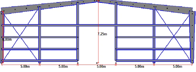
Figure 1: Elevation of Pre-Engineered Frame
Figure 2: Elevation of Conventional Frame
Design Data-
Main Frame-
Frame Type - Clear Span, Rigid Frame. Support- Pinned
Building Width (W) – 25 m (O/O Steel Columns) Building Length (L) – 60 m (O/O Steel Columns)
Bay Spacing- 11 @ 6 m Eaves height- 6 m Roof Slope- 1 in10
Grits Type-
Sidewall grits- Continuous End wall grits- Continuous
Purlin Type-
Roof Purlin- Continuous Spacing- 1.5m c/c
Panel Type-
3.2 LOAD CALCULATIONS 3.2.1 Calculation of static loads:
Dead loads are considered as per Table-2 of IS 875 (Part-1) – 1987
Weight of the G.I sheeting = 0.05 kN/m2 (class 1 G.I sheeting, thickness 0.5 mm) Self-weight of section = 0.05 kN/m2
Total weight = 0.10 kN/m2 Spacing of purlin = 1.5 m Bay spacing = 6 m
Total weight on frame = 0.10 x 6 = 0.6 kN/m
Live load are considered as per Table-2 of IS 875 (Part-2) – 1987 Live load on the sloping roof = 0.75 kN/m2
Live load on rafter = 0.75 x 6 = 4.5 kN/m
3.2.2 Calculation of Wind Loads:
Wind loads are calculated as per IS 875 Part III (1987), in this example. For the Present work, the basic wind speed (Vb) is assumed as 44 m/s and the building is considered to be open terrain with well scattered obstructions having height less than 10m with maximum dimension more than 50m and accordingly factors K1, K2, K3 have been calculated as per IS 875 Part III (1987).
Terrain Category- 2, Class- C K1- Probability factor- 1.0
K2- Terrain, height and size factor- 0.93 K3- Topography factor- 1
Design wind speed, Vz= Vb (K1 x K2 x K3) Vz= 40.92 m/s
Design pressure, P= 0.6 Vz² = 1.005 kN/m²
Ratio- H/W=0.24, L/W= 2.4
Wind Pressure Coefficients-
External and Internal wind coefficients are calculated for all the surfaces for both pressure and suction. Openingin the building has been considered less than 5% and accordingly internal coefficients are taken as +0.2 and -0.2.
The external coefficients and internal coefficients calculated as per IS 875 Part III (1987). Wind load on individual members are then calculated as below.
F= (Cpe – Cpi) A Pz
Where, Cpe, Cpi are external coefficients and internal coefficients respectively and A and P are Surface Area inm² and Design Wind Pressure in kN/m² respectively.
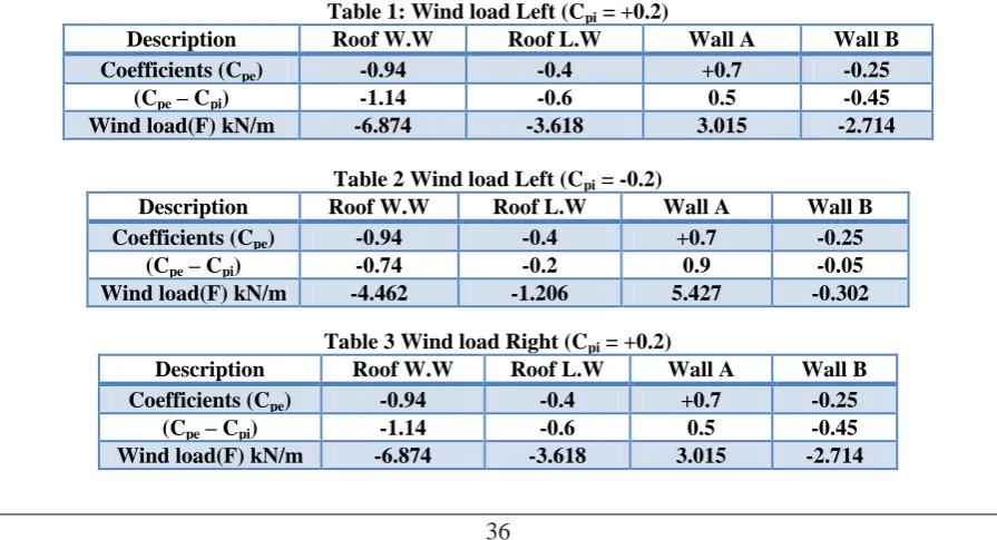
Table 1: Wind load Left (Cpi = +0.2)
Description Roof W.W Roof L.W Wall A Wall B Coefficients (Cpe) -0.94 -0.4 +0.7 -0.25
(Cpe – Cpi) -1.14 -0.6 0.5 -0.45
Wind load(F) kN/m -6.874 -3.618 3.015 -2.714
Table 2 Wind load Left (Cpi = -0.2)
Description Roof W.W Roof L.W Wall A Wall B Coefficients (Cpe) -0.94 -0.4 +0.7 -0.25
(Cpe – Cpi) -0.74 -0.2 0.9 -0.05
Wind load(F) kN/m -4.462 -1.206 5.427 -0.302 Table 3 Wind load Right (Cpi = +0.2)
Description Roof W.W Roof L.W Wall A Wall B Coefficients (Cpe) -0.94 -0.4 +0.7 -0.25
(Cpe – Cpi) -1.14 -0.6 0.5 -0.45
Table 4 Wind load Right (Cpi = -0.2)
Description Roof W.W Roof L.W Wall A Wall B Coefficients (Cpe) -0.94 -0.4 +0.7 -0.25
(Cpe – Cpi) -0.74 -0.2 0.9 -0.05
Wind load(F) kN/m -4.462 -1.206 5.427 -0.302
Table 5 Wind load Parallel (Cpi = +0.2)
Description Roof W.W Roof L.W Wall A Wall B Wall C Wall D Coefficients (Cpe) -0.94 -0.4 +0.7 -0.25 -0.6 -0.6
(Cpe – Cpi) -1.14 -0.6 0.5 -0.45 -0.8 -0.8
Wind load(F) kN/m -3.437 -1.809 1.508 -1.357 -4.02 -4.02
Table 6 Wind load Parallel (Cpi = -0.2)
Description Roof W.W Roof L.W Wall A Wall B Wall C Wall D Coefficients (Cpe) -0.94 -0.4 +0.7 -0.25 -0.6 -0.6
(Cpe – Cpi) -0.74 -0.2 0.9 -0.05 -0.4 -0.4
Wind load(F) kN/m -2.231 -0.603 2.714 -0.151 -2.01 -2.01
3.3 Weight of Steel (Steel Take Off)
3.3.1 Weight of the steel for the conventional steel building
In order to calculate the steel weight of conventional steel building the following member properties are used (Table 7). Hot rolled “I” sections are assigned for beams and columns. For purlins, girts and eave strut Z sections are used. Now using the above parameters the length and weights are calculated accordingly.
Table 7: Steel take-off for conventional steel building Profile Length (m) Weight (t) ST ISMB250 12.56 4.584
ST ISMB300 2.50 1.081
ST ISMB450 6.00 4.254
ST ISMB550 18.56 18.837
ISA 75X75X6 170.95 11.372
ISA 50X50X6 171.93 7.52
ST 200Z60X2 1560 8.547
Total = 56.17
3.4.2 Weight of the steel for the PEB with primary frame spacing 6 m
In order to calculate steel weight of PEB of primary frame spacing 6 m the following member properties are used (Table 8). For columns and rafters Tapered “I” sections are assigned. For the purlins and girts cold formed “Z” sections are used. For bracings Indian standard angle sections are used. Now using the above parameters the lengths and weights are calculated accordingly.
Table 8 Steel take-off for the PEB with primary frame spacing 6 m Profile Length (m) Weight (t) Tapered MembNo: 1 6.00 2.503
Tapered MembNo: 2 12.56 8.975
Tapered MembNo: 3 12.56 7.921
Tapered MembNo: 4 6.00 3.308
ST ISMB300 2.50 1.081
ISA 75X75X6 170.95 11.372
ISA 50X50X6 171.93 7.502
ST 200Z60X2 1560 8.547
Total = 42.66
Figure 4 Primary Frame showing Sections
Graph 1 Weight Comparison between CSB and PEB 6 m span.
0 10 20 30 40 50 60
1 56.17
42.66
Wei
gh
t
(To
n
s)
WEIGHT COMPARISON BETWEEN CSB AND PEB
6 M SPAN
IV.
EXAMPLE-2 INDUSTRIAL SHED
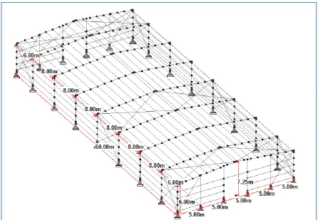
In this Example a 2D Plane Frame Pre-engineered building Frame is analyzed and designed. The plane frame is having width 25 m and bay spacing 8 m and eave height 6 m, subjected to wind load. A 5-Ton Crane System is considered. A 3-D PEB is shown in fig 5.
Figure 53-D structure of PEB of Primary Frame spacing of 8 m.
4.1 Loadings:
All loads are calculated as given in Section 3.1.
4.2 Weight of Steel (Steel Take-Off).
4.2.1 Weight of the steel for the PEB with primary frame spacing 8 m
In order to calculate steel weight of PEB of primary frame spacing 8 m the following member properties are used. For columns and rafters tapered “I” sections are used. For the purlins and cold formed “Z” sections are used. For bracings Indian standard angle sections are used. Now using the above parameter the lengths and weights are calculated accordingly.
Table 9 Steel take-off for the PEB with primary frame spacing 8 m Profile Length (m) Weight (t) Tapered MembNo: 1 6.00 2.641
Tapered MembNo: 2 18.56 12.320
Tapered MembNo: 3 12.56 6.794
ST ISMB300 2.50 1.081
ISA 75X75X6 170.95 11.372
ISA 50X50X6 171.93 7.502
ST 200Z60X2 1560 8.547
Graph 2 Weight Comparison between PEB 6 m span and PEB 8 m span.
V.
CONCLUSION
Pre-engineered steel structures building offers low cost, strength, durability, design flexibility, adaptability andrecyclability. Steel is the basic material that is used in the materials that are used for Pre-engineered steelbuilding. It negates from regional sources. Infinitely recyclable, steel is the material that reflects the imperativesof sustainable development.Based on the analytical and design results thereon of conventional and pre-engineered steel buildings, the following conclusions are drawn.
1. The total steel take-off for PEB with primary frame spacing of 6 m is 76% of the conventional steel building.
2. The total steel take-off for PEB with primary frame spacing of 8 m is 74.4% of the conventional steel building.
3. Steel take-off is more for PEB with primary frame spacing of 6 m than PEB with primary frame spacing of 8 m.
It is also seen that the weight of PEB depends on the Bay Spacing, with the increase in Bay Spacing up to certain spacing, the weight reduces and further increase makes the weight heavier.
To Conclude “Pre-Engineered Building Construction gives the end users a much more economical and better solution for long span structures where large column free areas are needed”.
REFERENCES
[1] IS 875 (part-1) “Code of practice for design loads (other than earthquake) for building and structures”, Dead loads, New Delhi, 1987.
[2] IS 875 (part-2) “Code of practice for design loads (other than earthquake) for building and structures”, Imposed loads, New Delhi, 1987.
[3] IS 875 (part-3) “Code of practice for design loads (other than earthquake) for building and structures”, Wind loads, New Delhi, 1987.
[4] Jatin D.Thakar, P.G. Patel, “Comparative Study of Pre-Engineered Steel Structure by varying width of Structure”, International Journal of Advanced Engineering Technology, Volume IV, Issue III, sept 2013, pp: 56-62.
41 41.2 41.4 41.6 41.8 42 42.2 42.4 42.6 42.8 43
1 42.66
41.71
Wei
gh
t
(To
n
s)
WEIGHT COMPARISON BETWEEN PEB 6 M
SPAN AND PEB 8 M SPAN
[5] Kanakambara Rao et al. “Design of Pre-Engineered steel structures building and to choose a material which offers low cost, strength, durability, design flexibility and recyclability”, International Journal of Engineering Research and Applications (IJERA), Vol. 2, Issue 2, April 2012, pp: 267-272.