E-ISSN 2308-9830 (Online) / ISSN 2410-0595 (Print)
Enhancing Vehicular Ad-hoc Network (VANET) Performance by
Congestion Control Algorithm
Ankeeta Patel1, Anuradha Gharge2, Parth Trivedi3, Dr.Madhukar Potdar4
1 Parul institute of engineering and technology
2 Head of Department (EC), Parul institute of engineering and technology
3 Project Scientist, Bhaskaracharya institute for space application and geo-informatics
4 Project Director, Bhaskaracharya institute for space application and geo-informatics
E-mail: [email protected]
ABSTRACT
Vehicular ad hoc networks (VANET) are a Class of MANETs used for communication among vehicles and between vehicles and roadside equipment. VANET provide the communication framework for dissemination of safety critical message such as beacons and emergency messages. Due to the technological involvement there are more number of wireless devices, which also creates more congestion in the wireless environment and greatly effect on the throughput, increases high-error rate, long-latency and data loss in congested environment which may leads to major vehicle accidents. So, the scheme which controls congestion is necessary to regulate the traffic level at an acceptable level. The proposed scheme includes study existing 802.11p standard and develop an algorithm on MAC to modify parameters like transmission power, Slot time and packet interval to reduce the congestion due to heavy broadcast traffic in the network for VANET.
Keywords:Enhancing, Vehicular Ad-hoc Network (VANET), Congestion Control, Algorithm.
1 INTRODUCTION
VANETS are a sub area of MANETS [1] (is Mobile Ad hoc Networks that can configure itself without wires) where the dynamic ad-hoc network is composed of vehicles as nodes. Vehicles utilizing wireless communication capabilities are termed as “computers networks on wheels” having data sharing capabilities. It aids in sharing information
among vehicles and nearby roadside
infrastructure.[2] Vehicles having this technology can improve road traffic safety by communicating emergency messages between vehicles so that drivers can take appropriate decisions timely. It also improves the traffic efficiency by intimating the following vehicle about to take a right path in case of traffic jam and other road situations.[3] VANET require IEEE 802.11p specification which include data exchange between the high speed vehicles. IEEE 802.11p is an approved minor
change to IEEE 802.11 to add wireless access in vehicular environment (WAVE).
Fig. 1. Typical VANET communication scenario[8]
According to Vehicular Communicative
V2V Vehicle to Vehicle Communication System Drivers can be made aware of surrounding traffic situation by exchanging information based on it. V2V also supports event driven messages in case of emergency and run application such as gaming, file downloading etc.
V2I Vehicle to infrastructure Communication System Vehicles can also get their information from Road side base station or other vehicles. Occupants of vehicles can access internet via RSU. Along with this, it can also provide information of parking lot availability, payment services, location based services etc.[3]
VANET has adopted Dedicated short range communication (DSRC).[8]DSRC uses 5.9GHz spectrum for communication, which is divided into seven channels. One of those seven channels is used for control channel (CCH) and other six are used for service channel (SCH). The CCH is used to transmit safety messages, and SCHs are used to transmit non-safety messages, where vehicles need to switch between the CCH and SCHs to transmit messages.[4]
There are mainly two application of VANET.one is Comfort application and other is safety application. Comfort application improves passenger comfort, traffic efficiency and optimizes the route to a destination. For e.g traffic information system, weather information, petrol pump location and interactive communication such as internet access or music download. Safety application increases the safety of passengers by exchanging safety related information via intervehicle communication. For e.g. emergency warning system, lane changing assistant, intersection coordination, road condition warning.[5]
2 RELATED WORK
In [6], author proposed joint adaptation of transmit rate and power to reduce channel congestion in vehicular Ad-hoc network. The rate and power adaptation directly effect on number of messages exchanged & number of vehicles in the awareness region respectively. By setting the collision rate value i.e. acceptable collision rate value (5% here) proposed algorithm adapts TR/TP value according to observed collision rate. Initially TR/TP value is selected between the interval
(TR/TP)minimum and (TR/TP)maximum values .If collision rate is higher than acceptable collision rate then it picks a TR/TP value in the interval between TR/TPminimum and current TR/TP value & if the collision rate is lower than acceptable collision rate then it picks a TR/TP value in the interval between current TR/TP & TR/TPminimum value. When communication overhead increases,collision rate also increases. To reduce collision rate first rate adaptation is applied until minimum required rate is reached and if the collision rate is still high then power adaptation is applied.
In [7], author proposed probability based MAC channel congestion control mechanism (PCC) to decrease channel congestion in vehicular environment. In this mechanism two functions are used called contestant estimation function and expected offset calculation function.in contestant estimation function each vehicle can count number of surrounding vehicle based on listening hello message in the listening interval. While in expected offset calculation function vehicle calculate the length of the offset slot based on surrounding vehicle. The main advantage of PCC mechanism is that each vehicle in the network vary the contention window size according to the number of neighboring vehicle. Here the CW value increase when number of vehicle increases.
In [8], author proposed joint adaptation of transmission power an contention window size to reduce channel congestion in vehicular environment. The speed of the vehicle is different in the different traffic condition like during traffic jam, traffic light, accident which result in dynamic topology of vehicular network. Also during late night and rural area the vehicle speed is very low so the connection between vehicle remain active for very short duration of time. To make this connection for long time one solution is there increase transmission power but it create high network interference and overhead.to overcome this problem dynamic adaptation of transmission power which means increase transmission power when local vehicle density is low and decrease transmission power when local vehicle density is high. Due to the prioritization of messages, messages related to accident have higher priority compare to other messages so they have lower contention window size which result in high transmission opportunity compare to other. According to current collision rate, increase or decrease respective contention window size.
after that partition that network into equal width of segment. The vehicle which is near to the center of the segment will be selected as the local coordinator. This local coordinator assign the time slot to each vehicle in that segment for beacons transmission. In the case of emergency message, time slot reservation carried out dynamically and time slot will be reserved for emergency message.so by using this mechanism emergency messages can be transmitted on timely manner without expense of beacons.
In [10], author proposed adaptive and reliable medium access control mechanism by combining carrier sense multiple access with time division multiple access to avoid collision effectively and use wireless resources efficiently. Here they introduce variable duration concept called “Chip” which have transmission period (TS) and reservation period. Transmission period is basically series of TDMA slots which is used by the nodes for their transmission while reservation period used by just newly incoming node to reserve a slot for transmission. When the local vehicle density is low then the duration of chip is short, for this case rest of the control channel duration can be used by the service channel to improve the throughput of the service channel. when the local vehicle density is high then the duration of the transmission period of control channel duration is high to make sure that every vehicle can transmit their safety packet successfully. In this case the duration of the control channel may be longer than service channel.
3 PROPOSED SOLUTION
As per 802.11p amendment of IEEE 802.11 for vehicular access in wireless environment, for all V2V (Vehicle to vehicle) communication all vehicles must use the same channel to transmit the safety data. All vehicles transmit broadcast safety message at some regular interval and / or at some critical time. As the number of vehicles increase in the range it increases the collision of wireless packets. As the messages are broadcast, there is no mechanism to detect collision for broadcast frame. So it need some changes at MAC layer to reduce congestion / collisions.
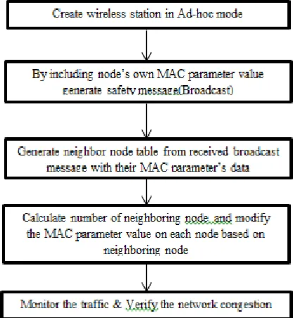
In the proposed technique, we will take the advantage of the MAC layer parameters which provides better performance and control in congestion of the broadcast domain in wireless network. First we understood the 802.11p standard and the congestion in the environment when multiple vehicles communicate with each other for warning and safety messages. All the nodes / vehicles transmit safety messages at regular
configured interval at the configured data rate and the transmit power. Each node / vehicle sends and extra information like own mac address, transmit data rate, transmit power, own contention window (CW) value, node number appended in the data payload. For V2V communication, each node broadcast this information in the message so all the node receiving the frame would parse the node information and maintain the node table which includes information of all the nodes in its range. The MAC layer parameters slot-time, transmit power, packet interval etc. will be modified from its default values to enhance the broadcast congestion in the network.
Fig. 2. Flow chart of proposed scheme
Dynamic Algorithm – 1 (TX Power, Packet
interval)
If the neighbor node count reaches to its threshold value then the node would change its Tx power to lower value than the current one. (E.g. if the current tx power is 23 dbm then it would decrease it to 20dbm). This will reduce the range and this node will not interfere the node which is at far distance. This way, the nodes which are far away from each other’s range can transmit simultaneously.
interval to 200ms to reduce the channel busy time by half and reduce the collision.
When the node wants to transmit the packet it sense the medium, if it sense the channel as busy it will wait till the medium to be free. In this method we take the difference of the value between now - current time and the time when medium will become idle. This difference value we add as a small jitter to main packet interval. So when the node sends the next packet from application we add this jitter. Every node add this jitter to its packet interval. So next time when node try to access the medium the chance of free medium is high compare to last transmission.
1. Gather the information and count of the neighboring node
2. If (neighbor node count > threshold) {
Decrease the Tx power; Increase packet interval; } 3. else {
Keep the Tx power same; Keep the packet interval same; }
Dynamic Algorithm – 2 (Slot time)
The slot time in 802.11p with 10MHz band it’s 13 us, and same in all the nodes in the networks. The same value of slots may create collision as number of back-off slots will multiply by slot duration (13 us) and as a result sometimes two nodes back-off expire at the same time and collision happens.
One solution for this is to vary slot duration over multiple nodes. So node1 has slot duration x, node2 has slot duration y, etc. In this way we are reducing chances of collision after making back-off duration to multiple of different number.
Dynamic Algorithm – 3 (AIFSN Value)
The effect of the varying the slot time can be compensated by varying the aifsn in reverse manner. The AIFSN (Arbitration inter-frame spacing) is the method which can prioritize the one Access Category over the other. With the help of this, the voice and videos can be prioritized over emails.
4 SIMULATION RESULT
For simulation of the congestion control techniques, we have used Network Simulator as a programming tool, NS-3 version. We have implemented the script of network simulator to simulate our experimental scenario of wireless nodes and its visualizer for graphical representation.
Table 1: Simulation Parameters for Experimental Setup
Parameter Value/Description
Number of Nodes in
the Network
40 Nodes (can be
varied)
Packet Size 500 bytes
Number of packets 100 packets
Message Interval 100 ms
Broadcast data rate 6 Mbps
Transmit Power ,
Packet interval
varied based on
surrounding nodes
Dynamic Algorithm –1 (TX Power, Packet interval) As the number of nodes increases in the network it increases the collision possibility. To overcome this issue if we reduce the power of each node in the congested network as a result each node forms a small cell around it and due to low tx power the node will not interfere with the far distance node. So all the nodes which are far from each other’s range can transmit simultaneously.
Fig. 3. 10 Nodes transmitting with maximum power (Default scheme)
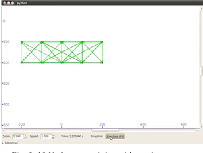
As shown in figure 3, if the number of node is less(10) then node cannot interfere with other node and cannot create the congestion even if higher transmit power. But if the number of node increases (40) then with higher transmit power more congestion in wireless environment as shown in figure 4.
Fig. 5. 40 Nodes transmitting with Proposed Scheme
figure 5 shows the result of the proposed scheme , in which for more number of node, the transmit power is less which reduce the congestion. Similarly we can adapt the contention window and packet interval value according to number of nodes. Table 2 shows the packet interval result statistics. Here in the default scheme the packet interval is constant for various number of vehicle while in proposed scheme packet interval is variable. So the number of packet received in proposed scheme is more compare to default scheme which reduce the collision.
Table 2: Packet interval result statistics
Dynamic Algorithm – 2 (Slot time)
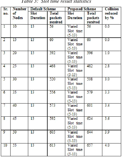
Below is simulated NS3 scenario result statistics where each node sending 20 packets each.
Table 3: Slot time result statistics
As shown in Table 3 by varying the slot duration in proposed scheme the number of packets received more compare to default scheme which reduce the collision.
Dynamic Algorithm – 3 (AIFSN)
Table 4: AIFSN result statistics
more compare to default scheme which reduce the collision.
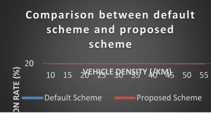
Fig. 6. Comparison between default scheme and proposed scheme
In the above graph, we have plotted the comparison between the default scheme verses the proposed scheme. The collision rate is lower in case of the proposed scheme because the MAC parameters on the each wireless node are configured properly based on the other nodes surrounding it (i.e. slot time, tx power, packet interval,AIFSN value etc.) in the wave/Wi-Fi MAC layer.
5 CONCLUSION
By study existing 802.11p standard and develop an algorithm on MAC to modify parameters which are like transmit power, packet interval, Slot time, AIFSN value etc., we can reduce the congestion due to heavy broadcast traffic in the network for VANET. Simulation result shows the proposed scheme has less collision rate compare to default scheme.
6 REFERENCES
[1] Sherali Zeadally, Ray Hunt, Yuh-Shyan Chen, Angela Irwin, Aamir Hassan; Vehicular ad hoc networks (VANETS): status, results, and challenges; Springer Science Business Media, LLC, 2010
[2] Harsch, C., Festag, A., & Papadimitratos, P.; Secure position-based routing for VANETs; In Proceedings of IEEE66th vehicular technology conference (VTC- 2007), Fall 2007 (pp. 26– 30), September 2007
[3] Parul Chaodhary, Umang,”Literature review on vehicular ad-hoc network for intelligent transport”, 2nd International
Conference on Computing for Sustainable Global Development, IEEE 2015
[4] Prasan kumar sahoo,Cheng-cheng chien,Ming-jer chiang,Shih-Lin Wu”A Novel Event Transmission protocol for vehicular Ad hoc
network”APWiMob 2014,Bali 28-30 ,IEEE 2014
[5] Salesh yous,Mohmoud siadat
mousavi,mahmood fathy,”Vehicular ad hoc
network(VANETs):challenges and
perspectives”,IEEE 6th international conference on ITS telecommunications proceedings,2006
[6] Sofiane Zemouri,Soufiene Djahel & John Murphy,”Smart adaptation of beacons transmission rate ans power for enhanced vehicular awareness in VANET”, IEEE 17th international conference on intelligent transportation system,October 2014
[7] Mark chi- wei hsu,tien-yuan hsieh,”A probability based MAC channel congestion control mechanism for VANET”,IEEE 2013 [8] Danda B. Rawat, Gongjun Yan, Dimitrie C.
Popescu, Michele C. Weigle, Stephan Olariu,“Enhancing VANET performance by joint adaption of transmission power an CW size”,IEEE transaction on parallel and distributed system ,vol. 22 ,No. 9 ,Sept 2011 [9] Shruti R. Kolte, Mangala S. Madankar
,”Adaptive Congestion Control For
Transmission Of Safety Messages in VANET”, International Conference For Convergence Of Technology, IEEE 2014
[10] Jinjie Guo,Yiding huo,Chang hu,Tianning liang,Yu liu & Lin zhang ,”An Adaptive and Reliable MAC Mechanism for IEEE 1609.4 and 802.11p VANETs”,IEEE 2014
0 20
10 15 20 25 30 35 40 45 50 55
C
O
LL
IS
IO
N
R
A
TE
(
%
) VEHICLE DENSITY (/KM)
![Fig. 1. Typical VANET communication scenario[8]](https://thumb-us.123doks.com/thumbv2/123dok_us/1328804.1641101/1.612.314.521.551.676/fig-typical-vanet-communication-scenario.webp)