195
A Modified Power-Efficient Gathering in Sensor
Information System (MOD-PEGASIS) for Routing
in Wireless Sensor Network
Navdeep Kumar Chopra, Rajesh Kumar Singh
Abstract— Wireless Networking (WSN) uses numerous sensor nodes with multiple processing, sensing capabilities in order to monitor/ track a particular area which is far from a human approach. Because sensor nodes are mainly battery-powered and are extremely limited in terms of energy sources, it is necessary to explore energy optimization methods to extend the life of the WSN. In this research work, we mainly focused on to minimize the unnecessary wastage of energy and hence enhance the network performance. A Modified power-efficient gathering in sensor information systems (Mod-PEGASIS) algorithm is designed to select an appropriate Cluster Head (CH) by hybridizing the Cuckoo Search (CS) and Firefly algorithm. Initially, the sensor nodes are deployed in the defined network area on random basis. Then, the entire network is divided into different clusters each includes an individual CH. After the formation of optimal route, the selection of route is done using artificial neural network (ANN) approach. The simulation results illustrated that the designed approach can effectively improve the network performance in terms of end-to-end delay, packet drop ratio and energy consumption rate. The energy up to 4.52 % is obtained compared to the existing work.
Index Terms— Wireless Sensor Network, Power-efficient gathering in sensor information systems, Cuckoo search, Firefly, Artificial Neural Network.
—————————— ——————————
1 I
NTRODUCTION SN is a kind of wireless communication network that consists of a large number of tiny elements known as nodes [1]. Due to their low deployment cost, these networks find application in distinct fields such as monitoring weather and environmental conditions, healthcare system and many more. WSN mainly consists of two sides such as; a Base Station (BS) and a number of sensor nodes that are communicating with each other by sensing physical parameters from the outside environment [2]. BS is used to collect data from these sensor elements and then take decision so that the data can reach the desired end-user. Each sensor nodes have performed different operations such as collection of data, data processing and then communication [3]. Fig 1, represents the block diagram of sensor node. The sensors are the tiny elements that are used to examine the physical quality like temperature, humidity and motion. The storage unit is utilized to memorize the collected sensor data [4]. The collected data is passed to the controller unit for further processing. The controller has taken decision like when and where the data is routed as well as responsible for data aggregation. The sensor nodes are powered by the batteries as the nodes are deployed in remote area [5]. The transceiver block is used for the reception as well as transmission of the data so that the nodes can communicate successfully within the network [6].Fig. 1. Block Diagram of a sensor node in WSN [7]
The working operation or the life of these nodes depends upon the battery attached to these nodes. Also, the nodes are deployed in the area which is far from the human approach [8]. Therefore, it is tough to replace or recharge node’s battery, which affects the overall performance or the lifetime of the
W
————————————————
Navdeep Kumar Chopra is currently pursuing research scholar program in Computer Science and Engineering in IKGPTU, Jalandhar, India. E-mail: [email protected]
Rajesh Kumar Singh is currently professor and principal in SUS Institute of Computer, Mohali, India.
E-mail: [email protected]
Transceiver
Embedde d Processor
Sensors Memory
Battery
Low cost process
or
Limited Life time 60 % of
total cost Limited
storage Antenna
196 network. To preserve node’s energy, become an essential task
in the communication of WSN. Due to battery exhaustion, failure of communication link as well as node’s may arise; therefore, an alternative route must be suggested immediately to the network to continue communication between the source and the end-user [9]. But the direct transmission between the source node and the destination node consume more energy compared to the transmission of data through multiple stages of shortest distance. At this point, the concept of clustering helps a lot, in which, the nodes have to communicate with the CH [10] instead of all neighboring nodes. Therefore, CH performs multiple tasks such as data aggregation, data compression and the transmission of data to the BS a well as to their nearby CH [11]. Every time, the nodes whether they are inactive mode or in idle mode consumes energy and hence to save energy-efficient routing protocol is used [12]. In this paper we have used PEGASIS as a routing protocol, which has been designed mainly to save energy so that the lifetime of the network can be increased. This protocol mainly has two targets one is to increase the lifetime of the sensor nodes by using collaborative scheme. The second one is to minimize bandwidth consumption by assigning the data to its nearby node.
1.1 Paper Contribution
The main focus of this paper is to design an energy-efficient routing protocol by adopting techniques such as clustering, swarm intelligence algorithms along with artificial intelligence technique. The designed protocol will provide the following contribution in the WSN:
1. PEGASSIS routing protocol is implemented to find best intermediate nodes in existing route for data transmission from the transmitter to the receiver node via CH.
2. To improve and create a secure route, a combination of CS with Firefly is used as an optimization technique for the better selection of CH.
3. ANN is used as a classifier mechanism with optimized PEGASIS routing to minimize the energy consumption rate for data transmission in WSN.
4. QoS parameters are calculated and compare with PEGASIS routing protocol to validate the designed routing mechanism.
The rest of the article is arranged as follows. Section2 describes the related work on WSN. Section 3, demonstrates the proposed network and approaches. Section 4, describes the results and discussion obtained after the experiment performed in MATLAB simulator. Section 5, concludes the overall research followed by its future opportunities.
2
R
ELATEDW
ORKA number of documents/ research papers related to energy optimization in WSN have been published. The
results/finding of those papers has been discussed in this section. The researchers Jie et al [13] in the year 2009 have proposed MAC-based protocol, which was later investigated to design an energy-efficient routing scenario. In his research, the authors have mainly focused to solve the issue of coverage area. Here, coverage area is defined as the requirement of nodes that are used to cover the given/desired area. The authors have designed a ―k-coverage‖ algorithm along with a novel objective function to reduce node’s total energy consumption as well as enhance the reliability of the nodes. According to their problem definition, the energy consumption rate can be stated as;
K*N*((r*r)/A)=.3849K
Where K, N, r and A, are known as the factor of energy consumption, the number of nodes, radius of coverage and area of the desired network respectively.
Many researchers have focused on energy conservation routing protocols in recent years. Nearly LEACH is the most popular hierarchical protocols that have been proposed twenty years ago [14]. There are mainly two kind’s nodes that a LEACH protocol includes such as CH and ordinary nodes. The ordinary nodes collect data from the desired area and transfer the data packet to its nearest CH. The CH receives the data and then send the data to the receiving node. The concept of CH has been used to avoid long-distance communication between the sink node and ordinary node and hence save much energy. The selection of CH is performed on random basis, which results to degrade the performance of the network. Also, as the CH’s are directly communicating with the sink node which causes large amount of energy dissipation.
197 (EEMER) has been presented. The network of a maximum of
200 nodes has been used during the experimental work. Also, to show the effectiveness of the proposed work comparison between traditional routing algorithms such as LEACH, PEGASIS and TEEN algorithms against EEMER algorithm in terms of end-to-end delay, energy consumption, and packet delivery ratio has been provided. The researchers have combined the PEGASIS routing algorithm with the evolutionary-based optimized scheme named as cuckoo search for the appropriate selection of CH during the process of clustering.
3 P
ROPOSEDW
ORKIn this research work, we have designed a simulation model for WSN using the concept of PEGASIS routing mechanism with hybridization of Cuckoo Search and Firefly optimization algorithm based on ANN as a classifier
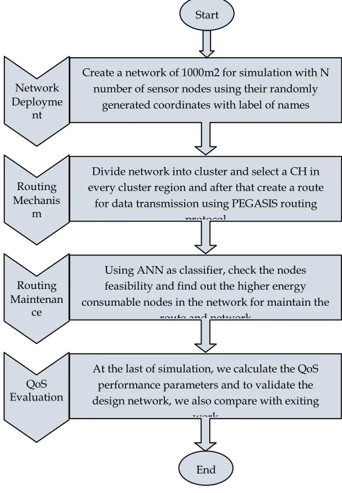
. The concept of PEGASIS routing mechanism is applicable for each communicating node to receive and transmit the data packets to closest neighbor nodes via cluster head which is as known as leader node. This routing approach works on the basis of energy load distribution mechanism in the network. The procedural steps of simulation are given in the form of block diagrams.
3.1 Network Creation
Firstly, we place the same number of nodes using the randomly generated x and y coordinates in the simulation area which is considered as 1000m2 and after that, a node is selected as transmitter node and other as receiver node based on random selection process.
3.2 Energy Model
During the simulation of the work, the energy model, which was presented by Jia et al. (13, 2009) has been considered. Following assumptions are considered;
1.Sensing radius of the node 2.Power loss in free space 3.Power loss in the channel
Therefore, the energy consumption of a single sensor node (k) can be determined as:
Where represents the energy consumption of node, and are represents the model of energy consumption in free space and multipath fading respectively. is the sensing radius of node. Therefore, the total energy calculated for the given network is defined as:
The energy consumption calculated per area is given as;
Represents the sensing area. The entire network is divided into 2×3 grids, and hence = .
The distance between the n numbers of sensor nodes is calculated by
Here, x y are the points within the sensing radius of node
Fig. 2. Proposed Work 3.3 CH selection
In this scenario, the hybridization of cuckoo search and firefly algorithm is used to select a cluster head for data transmission and a cluster head is assigned to each cluster region. We already know that PEGASIS routing mechanism faced several issues during selection of a cluster head. So the hybrid approach distributed the energy load equally among all nodes in the network and then find out the reliable node using the fitness function which is considered as cluster head or leader node.
Network Deployme
nt
Create a network of 1000m2 for simulation with N number of sensor nodes using their randomly
generated coordinates with label of names
Routing Mechanis
m
Divide network into cluster and select a CH in every cluster region and after that create a route
for data transmission using PEGASIS routing protocol
Routing Maintenan
ce
Using ANN as classifier, check the nodes feasibility and find out the higher energy consumable nodes in the network for maintain the
route and network
QoS Evaluation
At the last of simulation, we calculate the QoS performance parameters and to validate the design network, we also compare with exiting
work Start
198 3.4 Route Formation
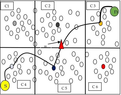
The designed wireless network, which consists of the number of nodes, is shown in Fig. 3. The network is divided into six number of clusters named as C1, C2, C3, C4, C5 and C6 respectively. With the help of hybridization of CS and Firefly algorithm for PEGASIS routing mechanism, we defined a CH in each cluster region, which acts as a leader node. In each cluster, the CH is represented by a different colour of circle whereas nodes are represented by simple circle. After that a route is created between transmitter nodes to receiver node using the concept of optimization. The working of PEGASIS routing algorithm is written as follows;
The main concept behind PEGASIS is to receive information from the transmitter node and send to its nearest node and behave like a leader node throughout the communication process. This process helps to distribute load evenly. The nodes are placed on a random basis and are arranged in such a manner so that a chain can be formed. On the other hand, it is the duty of the BS to execute this chain and then broadcast it to the entire network. The network has been simulated for 50 numbers of nodes in which a BS has been positioned at remote place from the nodes.
Fig. 3. Route Formation Using Mod-PEGASIS
For the formation of the chain, it is assumed that the entire nodes have global knowledge of the network a hence followed the greedy chain algorithm. The construction process of chain is started with the farthest node from the BS.
The working of PEGASIS routing is based on the distribution of energy to each node in a balanced way. So, this routing protocol always considered the farthest neighbour node in route for data transmission because energy consumption of each node is same. The source node transmits data to its nearest CH, and the CH send data to the farthest CH which is nearest to the BS as shown in Fig. 3. After that BS send data to the CH which is nearest to the receiving node and farthest from the BS. After that the data transmission starts and the route maintenance process is described in the following section. The working algorithm of Mod-PEGAIS is written as follows
Algorithm: Mod- PEGASIS using CSA and FFA
Requirements: Nodes (N), Properties of Nodes (P), Coverage Area (CA), Coverage Limit (CL), Transmitter node (TX), Receiver node (RX), Cluster Head (CH) and Base Station (BS)
Output: R-TX to RX: Route from transmitter node (TX) to receiver node (RX) via Cluster Head (CH) and Base Station (BS)
For each N do with respect to i Node-Energy = N (i)
Balance the node energy using PEGASIS protocol If N (i) == Balanced
Node-Energy = not required balancing of energy Else
Node-Energy = required balancing of energy End
End
Based on the Node-Energy, divide to network into sub region which is known as cluster and create a cluster head in each cluster and to select cluster head, hybridization of CSA and FFA is used
Call CSA with their operating functions – Egg Size (ES-All Node-Energy)
– Current Egg (CE-Particular Node-Energy) – Respective Eggs (RE-Neighbor Node-Energy) Set fitness criteria of CSA for cluster head selection Fitness_function, f (f) = True; if
False; otherwise
Calculate size of Node-Energy such as (R-row, C-column)
For each R do with respect to i For each C do with respect to j
Fs= CE (i, j) Ft= RE (i, j)
f (f) =Call Fitness_function (Fs, Ft) Fitdata=CSA (f (f), ES)
End
End
If Fitdata == True
Consider as CH
Else
Consider as Normal communicating node
End
To validate the selected CH by CSA, FFA is used Call FFA with parameter – Iterations (ITR)
– Population of Firefly (S) – Fitness function f (fit) – Selected CH (SCH) Calculate, T = Number of Selected CHs Fitness function:
Fitness_function, f (fit) = True; if selected CH is better False; otherwise
For each T and ITR do with respect to i
Fs= Node-Energy SCH (i) Ft= Node-Energy of S (i) / N f (fit) =Call Fitness_function (Fs, Ft) FitCH=FFA (f (fit), ES)
S
D
C1 C 2 C 3
C 4
C 5 C6
199
End
If CH == FitCH
Selected CH by CSA is true
Else
Selected CH by CSA is true
End
Create an empty Route, R= [] R (1) = TX
Search nearest CH with respect to the TX R (2) = Nearest CH
. .
R (mid) = BS .
.
R (Last) = RX
Returns: R as a route from transmitter node (TX) to receiver node (RX) via Cluster Head (CH) and Base Station (BS)
End
3.5 Route Maintenance
After that, data transmission is starting using the selected route by hybrid approach and if any communication problem occurs then the concept of ANN is utilizes to detect the irrelevant nodes in the node which is the cause of energy consumption.
Algorithm: ANN
Input: Nodes features as a Training Data (T), Target (G) and Neurons (N)
Output: Selection of best route
Initialize ANN with distinct constraints – Epochs (E) – Performance parameters: MSE, Gradient, Mutation and Validation Points
For each set of T
End
Initialized the ANN using T & G
Net = Newff ( )
Set the training constraints as per desire and train the network Net = Train ( )
Classify = fail node within route using trained Net
If Classify = True
Optimized route = Node consider in route
Else
Node not consider in route
End
Return; Optimized Route with best intermediate nodes
End
4 R
ESULTS ANDD
ISCUSSIONThe proposed Mod-PEGASIS routing protocol is implemented in MATLAB simulator by using the concept of optimization and artificial intelligence. The modifications in PEGASIS routing mechanism have been executed with WSN. The simulation parameters that have been assumed during the execution are shown in table 1.
TABLE 1 SIMULATION PARAMETERS
Number of Nodes 100, 120, 140, 160, 180, 200
Channel Type Wireless Traffic Type TCP Antenna Type Omni-directional
MAC Type IEEE 802.15.4 Routing Protocol Mod-PEGASIS Number of packets 50
Simulation Area 1000×1000 square meter
The result of the designed routing algorithm has been calculated in terms of packet drop rate, delay and residual energy of the nodes. The performance of the presented energy-efficient algorithm is compared with PEGASIS and ModPEGASIS algorithm as shown in table 2.
TABLE 2 END- TO END DELAY (MS) Number
of Nodes PEGASIS PEGASIS Mod- EEMER
100 6.8 4.8 5.0 120 7.2 5.6 6.0 140 8.7 6.7 7.0 160 10.5 6.9 7.1 180 14.6 7.8 8.2 200 18.7 8.2 8.5
Fig. 4. Delay analysis of the proposed model
200 technique. From the Fig, it is clearly seen that the end to end
delay has been increased with the increase in the number of nodes. The reduction in the delay of about 52.2 % has been examined when the number of nodes is at 200 and about 29.41 % while considering 100 numbers of nodes.
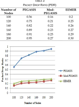
TABLE 3
PACKET DROP RATIO (PDR)
Number of
Nodes PEGASIS PEGASIS Mod- EEMER
100 0.56 0.16 0.2 120 0.75 0.21 0.25 140 0.82 0.22 0.26 160 0.89 0.23 0.27 180 0.91 0.25 0.29 200 0.95 0.27 0.30
Fig. 5. PDR
The next QoS parameter that has been considered in justifying the performance of the designed Mod-PEGASIS protocol is the PDR that has been shown in the form of a graph as depicted in Fig 5. It has been observed that the traditional cluster-based technique (PEGASIS) make sure a maximum transmission of data packet while integrating with optimized and artificial intelligence techniques. From the graph an enhancement of about 65.43% from the traditional PEGASIS approach and about 15.38 % compared to the existing EEMER approach.
TABLE 4
ENERGY CONSUMPTION (J) Number of
Nodes PEGASIS PEGASIS Mod- EEMER
100 70 55 60
120 195 160 180 140 240 195 220
160 355 330 340 180 385 370 380 200 487 475 480
Fig. 6. Energy Consumption
The measured energy consumption with a different number of nodes has been presented in Fig 6. From the above graph it has been clearly observed that with the increase in the number of nodes the energy consumption has also been increased. The percentage reduction in the energy consumption of the proposed Mod-PEGASIS approach compared to the simple PEGASIS routing algorithm is about 8.49 % and about 4.52 % compared to existing EEMER techniques.
5 C
ONCLUSIONIn this research article, an energy-efficient Mod-PEGASIS algorithm for WSN based on hybridization of CS and Firefly algorithm using ANN has been designed. Using PEGASIS routing we achieve a balance between energy utilization by each node. This is obtained by adjusting the sensing radius of every node. Initially, the nodes along with BS are deployed randomly in the defined network area and then the network is divided into different grids. The energy consumption of each grid has been measured. Then, the CS with Firefly algorithm is used to adjust the radius of sensing node as well as to select appropriate CH. Finally, we adopt ANN classification approach to select the efficient route between transmitter and receiver end. Simulation results show that the designed Mod-PEGASIS approach perform better compared to simple PEGASIS and existing EEMER approach.
R
EFERENCES[1] Singh, Bipandeep, Er Simranjit Kaur, and Bipandeep Singh, ―An Improved Energy-Efficient BBO-Based PEGASIS Protocol in Wireless Sensors Network,‖ Int. Journal of Engineering Research and Applications 4.3 (2014): 470-474.
201 Reliable And Efficient Communication In Wireless Sensor
Networks,‖ International Journal of Innovative Computing, 2012, Vol. 8, No. 18, October 2012.
[3] Cui, Z., Cao, Y., Cai, X., Cai, J., & Chen, J. ―Optimal LEACH protocol with modified bat algorithm for big data sensing systems in Internet of Things‖. Journal of Parallel and Distributed Computing, (2018).. [4] Mareli, M., & Twala, B. ―An adaptive Cuckoo search algorithm for
optimization‖. Applied Computing and informatics, 14(2), (2018), 107-115.
[5] Khabiri, M., & Ghaffari, A. ―Energy-aware clustering-based routing in wireless sensor networks using cuckoo optimization algorithm‖. Wireless Personal Communications, 98(3), (2018),.2473-2495.
[6] Gupta, V., & Doja, M. N. H-leach: ―Modified and efficient leach protocol for hybrid clustering scenario in wireless sensor networks‖. In Next-generation networks (pp. 399-408). (2018), Springer, Singapore.
[7] Somauroo, A., & Bassoo, V. ―Energy-efficient genetic algorithm variants of PEGASIS for 3D Wireless Sensor Networks‖. Applied Computing and Informatics, (2019).
[8] Biswas, S., Das, R., & Chatterjee, P. ―Energy-efficient connected target coverage in multi-hop wireless sensor networks‖. In Industry interactive innovations in science, engineering and technology (pp. 411-421), (2018), Springer, Singapore.
[9] Cheng, L., Niu, J., Luo, C., Shu, L., Kong, L., Zhao, Z., & Gu, Y. ―Towards minimum-delay and energy-efficient flooding in low-duty-cycle wireless sensor networks‖. Computer Networks, 134, (2018), 66-77.
[10] Wang, J., Ju, C., Gao, Y., Sangaiah, A. K., & Kim, G. J. ―A PSO based energy efficient coverage control algorithm for wireless sensor networks‖. Comput. Mater. Contin, 56, (2018), 433-446.
[11] Khasawneh, A., Latiff, M. S. B. A., Kaiwartya, O., & Chizari, H. ―A reliable energy-efficient pressure-based routing protocol for underwater wireless sensor network‖. Wireless Networks, 24(6) (2018). 2061-2075.
[12] Sarkar, A., & Murugan, T. S. ―Cluster head selection for energy efficient and delay-less routing in wireless sensor network‖. Wireless Networks, 25(1), (2019). 303-320.
[13] Jia, J., Chen, J., Chang, G., Wen, Y., & Song, J. ―Multi-objective optimization for coverage control in wireless sensor network with adjustable sensing radius‖. Computers & Mathematics with Applications, 57(11-12), (2009)., 1767-1775.
[14] Heinzelman, W. R., Chandrakasan, A., & Balakrishnan, H. ―Energy-efficient communication protocol for wireless microsensor networks‖. In Proceedings of the 33rd annual Hawaii international conference on system sciences(pp. 10-pp). (2000, January). IEEE. [15] Lindsey, S., & Raghavendra, C. S. PEGASIS: ―Power-efficient
gathering in sensor information systems‖. In Proceedings, IEEE aerospace conference (Vol. 3, pp. 3-3). (2002, March). IEEE.
[16] Xie, G., & Pan, F. ―Cluster-based routing for the mobile sink in wireless sensor networks with obstacles‖. IEEE Access, 4, (2016), 2019-2028.
[17] Zhu, C., Wu, S., Han, G., Shu, L., & Wu, H. ―A tree-cluster-based data-gathering algorithm for industrial WSNs with a mobile sink.‖ IEEE Access, 3, (2015).381-396.
[18] Ezhilarasi, M., & Krishnaveni, V. ―An evolutionary multipath energy-efficient routing protocol (EMEER) for network lifetime enhancement in wireless sensor networks‖. Soft Computing, (2019).
![Fig. 1. Block Diagram of a sensor node in WSN [7]](https://thumb-us.123doks.com/thumbv2/123dok_us/8635400.1425108/1.612.317.576.345.647/fig-block-diagram-sensor-node-wsn.webp)