Sharif University of Technology
Scientia IranicaTransactions B: Mechanical Engineering www.scientiairanica.com
Research Note
Numerical solution of homogeneous double pipe heat
exchanger: Dynamic modeling
H. AliHosseinpour
a, Y. Kazemi
band M. Fattahi
a,c;a. Department of Chemical and Petroleum Engineering, Sharif University of Technology, Tehran, P.O. Box 11155-9465, Iran. b. Department of Chemical Engineering, Razi University, Kermanshah, Iran.
c. Department of Chemical Engineering, Abadan Faculty of Petroleum Engineering, Petroleum University of Technology, Abadan, Iran.
Received 11 April 2012; received in revised form 2 September 2013; accepted 19 October 2013
KEYWORDS Heat exchanger; Homogeneous modeling; Double pipe; Structured mesh; Finite dierence.
Abstract.Dynamic modeling of a double-pipe heat exchanger is the subject of the current study. The basis of this study is the same velocity of vapor and liquid phases or, in other words, homogeneous phase, in the annulus part of the exchanger. The model can predict the temperature and vapor quality along the axial pipe from the pipe inlet up to a distance where steady state conditions are achieved. The simulation is conducted for two modes of co- and counter-ow in a one dimensional transient system. The physical properties of water are estimated from empirical correlation and a saturated vapor table with cubic spline interpolation. The exchanger model, which is a set of Ordinary Dierential Equations (ODEs), ODEs and algebraic equations, has been solved numerically. Modeling results have been investigated for dierent operating times and two modes of co- and counter-current. © 2014 Sharif University of Technology. All rights reserved.
1. Introduction
Heat exchangers are widely used in industrial appli-cation processes such as power plants, gas turbines, air conditioning, refrigeration, (domestic, urban, or central) heating, and cryogenic systems, among many others. Their universal application has led to research into a better comprehension of their dynamic behavior, modeling, simulation, identication, and control [1]. Many reports on numerical and experimental simula-tions for laminar or turbulent ow and heat transfer, concerning the employment of solid extended surfaces, such as ns and baes, can be found in the litera-ture [2,3]. Most of these works discuss the optimal spacing, shapes and orientations of these structures, *. Corresponding author. Tel.: +98 918 334 8863
E-mail addresses: hap [email protected] (H.
AliHosseinpour); yaser [email protected] (Y. Kazemi); [email protected] (M. Fattahi)
which enhance the heat transfer performance for a given pumping power or ow rate [4]. The objective of any such equipment is to maximize the heat transferred between the two uids. Therefore, a design which in-creases the heat transferred, but simultaneously keeps the pressure drop of the uid owing in the pipes to permissible limits, is very necessary. A common problem in industry is to extract maximum heat from a utility stream coming out of a particular process, and to heat a process stream [5]. The design of the heat exchanger might be developed by means of analytical methods. These methods give a quick and global approach to their behaviour. However, a large number of hypotheses and simplications have to be assumed. Examples are the F factor or " NTU methods [6]. More general and accurate approaches require the use of numerical methodologies, which subdivide the heat exchanger into many elemental volumes and solve the governing equations for each volume. In the two-phase ow region, the governing equations (mass, momentum
and energy) can be formulated in dierent forms, de-pending on the model used. Homogeneous models [7], drift ux models [8] or two-uid models [9,10] can be employed to solve the two-phase ow present in the condensation and evaporation process. To get a deep understanding of the mathematical model and the strategies for solving the governing equations, the double pipe heat exchanger may be a good option for application, due to its relatively simple geometry for the secondary ow. For example, numerical and analytical results in steady and transient states have been compared in dierent studies on double pipe heat exchangers [1,11,12]. A combination of analytical expressions with numerical methods is used in the double pipe helical heat exchanger resolution [13], where a CFD modeling, together with a " NTU method, is used to solve the heat exchanger.
This paper shows a more general approach for simulation of the two-phase ow inside the annulus and liquid inside the center tube. The uid region equations in the heat exchanger were discretized and a simulation was performed for one dimension. Moreover, variation of uid properties in a radial direction was neglected. First, details of the mathematical formulation and the numerical techniques are shown. Then, numerical aspects are presented and, nally, the results obtained from comparisons of co and counter current operat-ing conditions will be demonstrated.
2. Model description
Taking into account the following basic assumptions, the governing equations have been derived:
Homogeneous phase assumes a slip ratio (G = Uv=U1) equal to unity (both phases travel at the
same velocity);
One-dimensional ow is performed;
The exchanger is horizontal, so the gravity eects are omitted;
The wall of the heat exchanger is smooth and does not apply friction eects on owing uids;
The velocity prole is only a function of uid direction, and radial dependency is neglected;
The system is adiabatic and insulated (i.e. heat transfer through outer surface is neglected);
The uid owing in the inner tube is incompressible and single phase;
The outlet vapor as well as the inlet vapor is in a saturated state;
Pressure drops across vapor and liquid phases in the annulus tube are the same (dPv= dPl= dP );
In the annulus tube, the temperatures of vapor and liquid at each node are the same and are equal to
saturated temperature at node pressure (Tv = Tl=
Tsat);
Axial heat conduction inside the uid is neglected;
Working uid in the tube and the annulus sections is water;
The inlet vapor into the annulus tube is saturated with a quality of one and the inlet liquid in the inner tube is in a saturated condition.
As noted in the above assumptions, the cooling liquid temperature increases and the steam tempera-ture decreases. Consequently, the saturated vapor in the annulus part may provide two phases with the elevation of pressure drop. The vapor remains in a saturated condition through the exchanger, while its temperature, pressure and quality might vary along the exchanger and/or with time.
2.1. Governing equations in annulus tube Usually, rst law of thermodynamics for open systems, and considering the velocity term as u = _mt=(tAt) in
kinetic terms, gives: @
@t(tCpAtTsat) + _mt d dz(ht+
1 2u2)
+ 2RoUoverall(Tsat T ) = 0: (1)
Based upon the Maxwell's relations the following equa-tions are obtained:
(
dh= TdS+ dP
dhl= TldSl+ ldPl
) dhdzt = hldxdz + CptdT sat
dz + t dP
dz; (2)
hl = h hl: (3)
The following equation, known as the Clapeyron equation, demonstrates the relation between saturated temperature and pressure:
dP dTsat =
hl
Tsatl; (4)
l = l: (5)
Finally, the governing equation for the annulus pipe (Eq. (6)) would be obtained by combining Eqs. (2) to (5) with the initial and boundary conditions (Eq. (7)):
@
@t(tCpAtTsat) + _mt(hl dx dz + Cpt
dTsat
dz + tTsathl
l dTsat dz + 1 2 du2 dz )
(
I:C: Tsat= Tsat
in at (z; t = 0)
B:C: Tsat= Tsat
in at (z = 0; t)
(7)
At= (R2t R2o): (8)
2.2. Governing equations in the center tube 2.2.1. Governing equations in center tube for
co-current stream
The governing equations for the center pipe are valid, the same as for the annulus tube, however, the vapor quality is zero. Therefore, the equation might be expressed as follows:
@
@t(lCplAiT ) + _ml dhl
dz
2RoUoverall(Tsat T ) = 0; (9)
Ai= Ri2; (10)
in which, the initial and boundary conditions are: (
I:C: T = Tc
in at (z; t = 0)
B:C: T = Tc
in at (z = 0; t) (11)
2.2.2. Governing equations in the center tube for counter-current stream
According to the system of equations presented, the counter current condition formulation is given by:
@
@t(lCplAiT ) _ml dhl
dz
2RoUoverall(Tsat T ) = 0; (12)
whereas, boundary and initial conditions are: (
I:C: T = Tc
in at (z; t = 0)
B:C: T = Tc
in at (z = L; t)
(13) In the aforementioned equations, the initial and bound-ary conditions are the same. This means that, initially, the annulus tube is lled with saturated vapor and in the inner tube, cooling liquid ows without heat transfer and, suddenly, the streams switch to exchange the heat. Utilization of the above initial conditions is guaranteed to avoid division by zero at the beginning of the solution. Besides, this technique leads to the exact modeling of the equations.
3. Physical properties
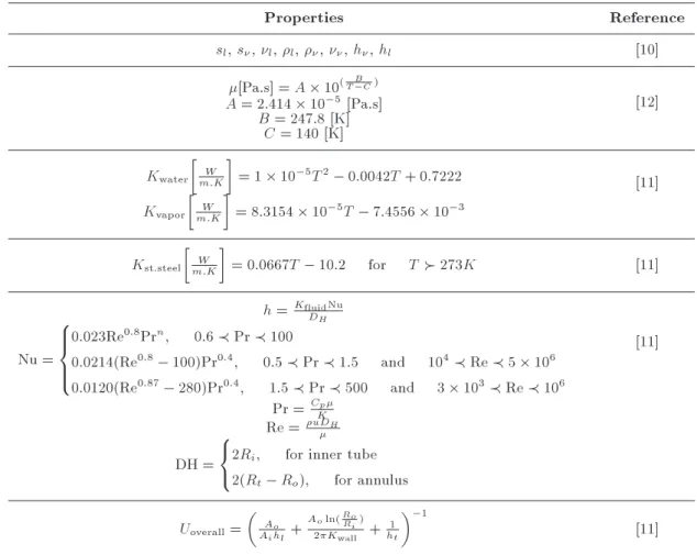
The physical properties of the heat exchanger, such as material selection, or uid properties in the inner and outer tubes, and overall heat transfer coecient at each point during the time, were calculated using steam tables by cubic spline interpolation or experimental relations that are listed in Table 1.
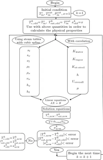
4. Numerical framework
According to the heat exchanger design, only axial heat transfer is considered and the system is meshed just in this direction. In order to simplify the calcula-tions, the meshes are assumed uniform and the mesh centered method of calculation was investigated. The calculation path reported here has been performed with structured mesh. Within this scheme, the linearization of equations was done. The algorithm of solution is illustrated in Figure 1. The resulting ordinary dier-ential equations were solved simultaneously using the nite dierence technique under initial and boundary conditions. The discrete formulation of the equations was fully implicit. At each step, the resulting set of linear algebraic equations was solved by the iterative Gauss-Seidel method with the relaxation factor. Solu-tion of the previous step was used as the initial guess for the iterative procedure. A computer program using MATLAB software (version 2010a) was developed to perform the above algorithm for numerical solutions.
The Clapeyron equation term in the annulus side equations causes nonlinearity. In order to obviate this restriction, the previous step time is used to calculate
Table 1. Estimation of physical properties of uids.
Properties Reference
sl, s, l, l, , , h, hl [10]
[Pa.s] = A 10(T CB )
[12] A = 2:414 10 5[Pa.s]
B = 247:8 [K] C = 140 [K] Kwater
W m:K
= 1 10 5T2 0:0042T + 0:7222
[11] Kvapor
W m:K
= 8:3154 10 5T 7:4556 10 3
Kst.steel
W m:K
= 0:0667T 10:2 for T 273K [11]
h = KfluidNu
DH
[11] Nu =
8 > > < > > :
0:023Re0:8Prn; 0:6 Pr 100
0:0214(Re0:8 100)Pr0:4; 0:5 Pr 1:5 and 104 Re 5 106
0:0120(Re0:87 280)Pr0:4; 1:5 Pr 500 and 3 103 Re 106
Pr = Cp
K
Re = uDH
DH = 8 < :
2Ri; for inner tube
2(Rt Ro); for annulus
Uoverall=
Ao
Aihl+
Aoln(RoRi)
2Kwall +
1 ht
1
[11]
the temperature. Thereby, a set of linear equations with constant coecients is obtained that might be solved by the iterative Gauss-Seidel method. In order to minimize errors caused by the above simplications, at each step, the equations are solved using the physical properties of the previous step (lagging). Then, ob-tained solutions are used for calculation of new physical properties and this repetitious loop, at each step, would be iterated over and over again up to when the property approaches a xed amount. Based on the energy balance at each node, the vapor quality at each step, due to the formation of liquid from vapor, is computed as follows:
q = _mtCpt(Tsatk Tsatk+1) = _mcond.hlv; (14)
_mcond.= _mtCpt(T k
sat Tsatk+1)
hlv ; (15)
x = _mt _mcond.
_mt : (16)
Reduction of temperature during time steps causes the condensation of the vapor. On the other hand, considering the same velocity assumption for vapor and liquid phases at each node, the total ow rate
is considered constant. However, the velocity at each node varies from others, due to dierent densities. Time steps in this method should be selected small enough to obtain reasonable solutions.
5. Results and discussion
In this paper, two scenarios of exchanger characteristics were used as the boundary conditions, as presented in Table 2. The scenarios are the same, except the mass ow rate of vapor. Variations of quality and temperature along the inner and annulus axial pipe, with two scenarios for co- and counter-current streams, are depicted in Figures 2-5.
The quality of vapor and temperature along the heat exchanger with a counter ow arrangement, under conditions of scenario I, is shown in Figure 2(a) and (b), respectively. As assumed, the exchanger is lled with pure and saturated vapor and a cooling liquid, which suddenly comes to exchange heat transfer. The saturated vapor is brought to a heat saturated liquid with a great initial heat transfer rate, leading to an extreme reduction in vapor temperature and quality. Thereafter, steady state conditions are achieved con-tinuously. As results show, the steady state conditions
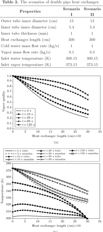
Table 2. The scenarios of double pipe heat exchanger.
Properties Scenario
I
Scenario II Outer tube inner diameter (cm) 13 13 Inner tube inner diameter (cm) 5.4 5.4
Inner tube thickness (mm) 1 1
Heat exchanger length (cm) 300 300 Cold water mass ow rate (kg/s) 1 1 Vapor mass ow rate (kg/s) 0:1 0:5 Inlet water temperature (K) 300:15 300:15 Inlet vapor temperature (K) 373:15 373:15
Figure 2. Vapor quality and temperature for counter-current versus length of double pipe heat
exchanger under scenario I with time step of 0:01 seconds.
in the heat exchanger would be obtained after 120 seconds.
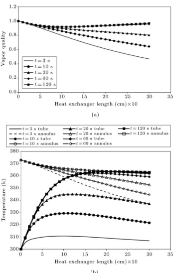
The temperature and vapor quality for the counter ow arrangement under scenario II is shown in Figure 3(a) and (b). The dierence between scenarios I and II is just the mass ow rate of saturated vapor. As Figure 3(a) clearly indicates, the reduction in vapor
Figure 3. Vapor quality and temperature for counter-current versus length of double pipe heat
exchanger under scenario II with time step of 0:01 seconds.
quality in scenario II is lower than in scenario I. From Figure 3(b), in scenario II, the uid temperature of the inner tube increases further and, also, the vapor temperature reduction is less; in other words, the eciency is lower.
The quality of vapor and temperature along the exchanger, with a co-current ow arrangement under conditions of scenario I, are shown in Figure 4(a) and (b). The saturated vapor is brought to a heat saturated liquid with a great initial heat transfer rate, leading to an extreme reduction in vapor temperature and quality. Thereafter, steady state conditions are achieved continuously. As the results show, the steady state conditions in the heat exchanger will be obtained after 120 seconds. In co-current ow close to the outlet end of the exchanger, the temperature dier-ence between inner and annulus tubes tends to zero. Therefore, the exchanger length could be decreased for economical considerations.
Figure 5(a) and (b) depict the vapor quality and temperature along the double pipe heat exchanger for
Figure 4. Vapor quality and temperature for co-current versus length of double pipe heat exchanger under scenario I with time step of 0:01 second.
co-current ow under scenario II. Trends similar to those of Figure 3(a) and (b) are observed. It is seen that the temperature increased sharply along the pipe close to the inlet end and, nally, reached a nearly constant value due to a reduction in heat transfer rate. Furthermore, it is observed that the vapor quality decreases through the exchanger.
Since inlet vapor is saturated, pressure distribu-tion at each node can be obtained simply by using steam tables. The reduction of vapor quality and elevation of inlet liquid temperature in the co-current conguration is less than in the counter current. This result shows that heat transfer eciency in the counter current arrangement is higher than in the co-current arrangement.
6. Conclusions
The present study is a numerical analysis of heat transfer in a double pipe heat exchanger with two congurations. The obtained results are exploited by
Figure 5. Vapor quality and temperature for co-current versus length of double pipe heat exchanger under scenario II with time step of 0:01 second.
highlighting the derived equations at the inner and annulus pipes. Physical parameters were predicted from correlations on the structure of the elds. The temperature and vapor quality along the axial pipe from the inlet, ending at a distance where steady state conditions are achieved, is predicted. The reduction of vapor quality in the co-current condition is less than in the counter current, which shows that the heat transfer eciency of the counter current is more than that of the co-current. When the mass ow rate of the vapor is increased, with the constant mass ow rate of coolant, heat transfer eciency decreases, as expected.
References
1. Rennie, T.J. and Raghavan, V.G.S. \Eect of uid thermal properties on the heat transfer characteristics in a double pipe helical heat exchanger", Interna-tional Journal of Thermal Sciences, 45, pp. 1158-1165 (2006).
2. Yuan, Z.X. \Numerical study of periodically turbulent ow and heat transfer in a channel with transverse n
arrays", International Journal of Numerical Methods for Heat and Fluid Flow, 10, pp. 842-861 (2000).
3. Tandiroglu, A. \Eect of ow geometry parameters on transient entropy generation for turbulent ow in circular tube with bae inserts", Energy Conversion and Management, 48, pp. 898-906 (2007).
4. Targui, N. and Kahalerras, H. \Analysis of uid ow and heat transfer in a double pipe heat exchanger with porous structures", Energy Conversion and Manage-ment, 49, pp. 3217-3229 (2008).
5. Swamee, P.K., Aggarwal, N. and Aggarwal, V. \Op-timum design of double pipe heat exchanger", Inter-national Journal of Heat and Mass Transfer, 51, pp. 2260-2266 (2008).
6. Kakac, S. and Liu, H. Heat Exchangers: Selection, Rat-ing and Thermal Design, CRC Press, Second Edition (2002).
7. Zurcher, O., Thome, J.R. and Favrat, D. \Evaporation of ammonia in a smooth horizontal tube: Heat trans-fer measurements and predictions", Journal of Heat Transfer, 121, pp. 89-101 (1999).
8. Garcia-Valladares, O., Perez-Segarra, C.D. and Rigola, J. \Numerical simulation of double-pipe condensers and evaporators", International Journal of Refriger-ation, 27, pp. 656-670 (2004).
9. Yadigaroglu, G. and Lahey Jr., R.T. \On the various forms of the conservation equations in two-phase ow", International Journal of Multiphase Flow, 2, pp. 477-494 (1976).
10. Ishi, M. and Hibiki, T., Thermo-Fluid Dynamics of Two-Phase Flow, Springer, New York, Second Edition (2011).
11. Abdelghani-Idrissi, M.-A. and Bagui, F. \Countercur-rent double-pipe heat exchanger subjected to ow-rate step change. Part I: New steady-state formulation", Heat transfer Engineering, 23, pp. 4-11 (2002).
12. Ansari, M.R. and Mortazavi, V. \Transient response of a co-current heat exchanger to an inlet temperature variation with time using an analytical and numerical solution", Numerical Heat Transfer Part A: Applica-tions, 52, pp. 71-85 (2007).
13. Rennie, T.J. and Raghavan, V.G.S. \Numerical studies of double-pipe helical heat exchanger", Applied Ther-mal Engineering, 26, pp. 1266-1273 (2006).
Biographies
Hossein AliHosseinpour obtained BS and MS de-grees in Chemical Engineering from the Department of Chemical and Petroleum Engineering at Sharif University of Technology, Tehran, Iran. His research interests include membrane synthesis and modeling in all elds of chemical engineering.
Yaser Kazemi obtained BS and MS degrees in Chem-ical Engineering from the Department of ChemChem-ical Engineering at Razi University, Kermanshah, Iran, in 2006 and 2009, respectively. His research interests include membrane preparation and modeling in the eld of chemical engineering.
Moslem Fattahi obtained a BS degree in Chemi-cal Engineering, in 2006, from Razi University, Ker-manshah, Iran, and his MS and PhD degrees, in 2008 and 2013 from the Department of Chemical and Petroleum Engineering at Sharif University of Technology, Tehran, Iran. His main research interests include modeling and reaction engineering, catalyst preparation, characterization and evaluation in the eld of chemical engineering.