Construction Installation Guide Concrete Reinforced
Shear Wall Cal Poly ARCE Department
Giovanni Dal Canto
California Polytechnic State University San Luis Obispo, California
California Polytechnic University prides itself on its “Learn by Doing” teaching procedures. The “Learn by Doing” atmosphere is ingrained in every student that attends the university. It is necessary for students especially in the ARCE field to obtain real life experience before entering the professional world. Ensuring that ARCE students have a means to practice and create new knowledge in the field of reinforced concrete shear wall testing is necessary to maintain Cal Poly’s education progression. Creating a reinforced concrete shear wall that can be built year after year for ARCE students to test on has been asked for by the ARCE department. The concrete reinforced shear wall focuses on testing wall types constructed in the 1970’s. These shear walls are common throughout California where earthquakes are prevalent. With the goal of the wall to be broken in shear and then patched using an FRP wrap, this demonstrates real life utilization of FRP wrap to structurally fix a building. With previous failures of delivery of a project of this type, a
compressive construction plan has never been more necessary. .
Key Words: Concrete, Shear, Earthquake, FRP, Construction
Introduction
shear wall. The project scope of the concrete-reinforced shear wall includes the fundraising and construction of a 5’ wide 12’-8” tall 5” thick wall. The project will be poured on the existing foundation where, after curing, it will be subjected to shear force by hydraulic jacks. Utilizing shear force to emulate the effects of an earthquake will break the wall. Once broken, the wall will be reinforced with FRP wrap and then subjected to force again. The goal is to test the strength and effectiveness of structural retrofit solutions.
This project was performed by a group of students consisting of, “two Graduate Architectural Engineering students, one Senior Construction Management/Architectural Engineering student, one Senior Construction Management student and two helpers for the construction: One second year Mechanical Engineering student and one third year Construction Management student” (Espitia 1) last year and after the test the ARCE department deemed this project one that they want to continue year after year . After significant issues with the construction quality, it was determined that a
comprehensive building plan is necessary to make this a sustainable project.
Project Scope
This project focuses on delivering a reinforced concrete shear wall that can reconstructed year after year by the ARCE department. The goal of this report is to present a seamless construction manual so issues and discrepancies in the construction process can be avoided. The project scope includes the construction of the concrete wall not limited to placement of concrete, rebar and wall stripping. The procedure to deliver this wall is discussed in the complete project installation manual.
Deliverables
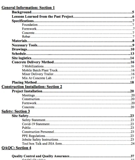
This project provided the deliverable of the Construction Installation Manual. This manual is broken down into the main sections of General Information, Construction Installation, Safety and Quality Assurance (QA) and Quality Control (QC). This report will discuss the contents and findings in these sections. Defined in this section is the project information that is necessary to safely deliver a quality project. Figure 1, demonstrates all deliverables that are included in the project which can be
Figure 1. Table of Contents
Construction Installation
The construction installation guide explains in detail how to install and complete the physical product in a step by step process. This is a guide that, with the exact procedures, needs to be followed to deliver the wall to project specifications and quality standard. The section is divided into two parts, form work and concrete. The form work section specifies the procedures necessary to construct the concrete formwork. One thing that is important to note is that the previous year’s foundation will be reused so there will be no form work that pertains to foundation construction. The concrete section explains the concrete placement method. Placement is discussed in the general information section, but this section gives specific installation instruction. The construction installation instruction
includes all aspects and information that is necessary to construct the wall on a jobsite. Figure 2. Is an example of what can be found in the project installation instructions. Information pertaining to the construction installation can be found in Appendix 1 Section 2.
Safety
QAQC
The QAQC section provides a quality checklist and defines the necessary steps to execute the project to the necessary quality. Last year’s project’s major flaw was its failure to ensures quality, so this section is extremely important. Users of this must follow the specified information to ensure a quality product is delivered to the client. All information discussed in this section can be found in Appendix A Section 4.
Lessons Learned from the Past Project
This project was first performed by a group of students in 2018-2019. This project was a joint project between CM students and ARCE students. The goal was to provide a concrete shear wall that emulated a wall utilized in Los Angeles hospital construction. With California continually experiencing earthquakes, the structural integrity of these walls has been called into question. One solution to fix damage from shear force is to use FRP wrap. Last year’s project used specifications and design that was common in the 1970s and was able to deliver a testable wall for the ARCE department. A wall was delivered but there were many quality issues with the final project. Pictures are unavailable of these quality failures as they are not noted in the previous reports. One major issue was that the wall bulged a total of 8” about 1 foot from the bottom of the wall. It is hard to accurately conclude the effects of FRP wrap it the wall has bulged a total of 4” making its actual thickness 13” at one spot when it was specified to be 5”. Ensuring the wall is completed to the project specifications is necessary to conclude the effects of FRP wrap.
After discussion, Terry Roy of McClone Construction, the owner of the plans for this wall, concluded that the sources of failure in last year’s project was failure to follow the plans and project
specifications. The first major mistake was the failure to use snap ties. Snap ties are a construction form system that holds two forms together and resist them from separating. Snap ties are necessary to prevent bulging and breakage in concrete form work. If snap ties were utilized in this project, it would have largely prevented the bulging of the form work.
Another failure in last year’s project was the failure to recognize that the plans call for a 4ft liquid limit per hour. What this means is that the form work is engineered to be poured at a rate of 4ft per hour. This ensures that the concrete has time to set up. Without letting the concrete set up, too much stress is put on the form work, causing the forms to bow. It is necessary that the form work
specifications are followed to ensure that the final product is to a high-quality standard.
The final issue that has been determined is that the plywood used did not follow the specified plywood on the drawings. Last year’s project did not use the called out ¾” MDO or plyform or SIM. This is a major mistake as they used OSB instead. Oriented Strand Board is strong in a non-form application. OSB being fused by compression and glue does not fare well in liquid applications. Utilizing OSB as the form plywood caused the form work to bow and warp. Water in the mix caused the OSB strands to separate which lead to a further decrease in the structural integrity of the form work.
upmost project quality. Quality issues in last year’s project can be directly attributed to negligence in the construction process, not engineering error.
Conclusion
Alkhrdaji, Tarek. “Strengthening of Concrete Structures Using FRP Composites.” STRUCTURE Magazine, www.structuremag.org/?p=8643.
Espitia, Carlos. “Interim Field Guide for Construction and Testing of Concrete Shear Wall with Added FRP Layer.” California Polytechnic State University San Luis Obispo, Digital Commons @ Cal Poly, 2019, pp. 1–10.
Murty, C.V. R., et al. Some Concepts in Earthquake Behavior of Buildings. Government of Gujarat, 2012.
Ostrom, Luke M. “IMPROVING DUCTILITY OF SLENDER REINFORCED CONCRETE SHEAR WALLS WITH FRP SHEETS AND SPLAY ANCHORS.” California Polytechnic State University San Luis Obispo, Digital Commons @ Cal Poly, 2018, pp. 1–46.
Construction Installation Guide Concrete Reinforced Shear
Wall Cal Poly ARCE Department
Giovanni Dal Canto
California Polytechnic State University San Luis Obispo, California
Table of Contents
General Information: Section 1
Background……….5
Lessons Learned from the Past Project………..…..6
Specifications………...7 Foundation………...7 Formwork……….7 Concrete………...7 Rebar………7 Materials………..8 Necessary Tools………...9 Drawings………10 Schedule………...………..13 Site logistics………..….14
Concrete Delivery Method………...16
3 Mobilizations………..16
Mobile Batch Plant Truck………..16
Mixer Delivery Trailer………...16
Mix At Concrete Lab……….17
Placing Method……….18
Construction Installation: Section 2
Project Installation………...20Meetings……….20
Construction………...20
Formwork………...20
Concrete……….20
Safety: Section 3
Site Safety………..23 Safety Statement………23 Covid-19 Statement………...23 Public……….23 Construction Personnel………..23 PPE Regulations………23Jobsite Safety Instructions……….23
Tool box Talk and JHA form……….24
QAQC: Section 4
Quality Control and Quality Assurance………37QAQC Checklist………37
Project Images………..39
Mission Statement
“To provide a sustainable project for students to practice “Learn by Doing” philosophies while ensuring quality and safety”
This manual is intended to provide the necessary details and information to perform this project year after year. This manual should be followed to ensure the safety and quality of
Background
Throughout the state of California, many buildings are out of code. Testing and research are necessary to provide solutions for patching and retrofitting buildings in the event of an
earthquake. Earthquakes cause buildings to be “subjected to random motion of the ground at its base which induces inertia forces in the building that in turn cause stresses” (Murty et al. 1). Although earthquakes are prevalent in California and are a problem that will never go away, their effects on buildings can be mitigated. With the, “current practice to improve the response of these walls is to increase cross sectional area by epoxying rebar into existing walls and spraying a layer of shotcrete, or adding new concrete shear walls to the building plan” (Ostrom 6) has proven to be extremely costly and time consuming. This project aims to demonstrate the effectiveness of Fiber Reinforced Panel (FRP) wrap and other reinforcement procedures in the future. FRP wraps are a cost effective and effective means of retrofitting concrete walls that have been subjected to shear force. Structure Magazine explains that, “FRP composite materials are comprised of high strength continuous fibers, such as glass, carbon, or steel wires, embedded in a polymer matrix”. FRP is an extremely effective fiber solution to solving structural issues.
Ensuring the quality and effectiveness of these materials is necessary for their widespread use and implementation in the field.
In order to test FRP and similar retrofits, Cal Poly San Luis Obispo (SLO) has setup a testing bay. They have tested a number of wall types in recent years and this project will focus on the concrete shear wall. The project scope of the concrete-reinforced shear wall includes the
fundraising and construction of a 5’ wide 12’-8” tall 5” thick wall. The project will be poured on the existing foundation where, after curing, it will be subjected to shear force by hydraulic jacks. Utilizing shear force to emulate the effects of an earthquake will break the wall. Once broken, the wall will be reinforced with FRP wrap and then subjected to force again. The goal is to test the strength and effectiveness of structural retrofit solutions.
Lessons Learned from the Past Project
This project was first performed by a group of students in 2018-2019. This project was a joint project between CM students and ARCE students. The goal was to provide a concrete shear wall that emulated a wall utilized in Los Angeles hospital construction. With California continually experiencing earthquakes, the structural integrity of these walls has been called into question. One solution to fix damage from shear force is to use FRP wrap. Last year’s project used specifications and design that was common in the 1970s and was able to deliver a testable wall for the ARCE department. A wall was delivered but there were many quality issues with the final project. Pictures are unavailable of these quality failures as they are not noted in the previous reports. One major issue was that the wall bulged a total of 8” about 1 foot from the bottom of the wall. It is hard to accurately conclude the effects of FRP wrap it the wall has bulged a total of 4” making its actual thickness 13” at one spot when it was specified to be 5”. Ensuring the wall is completed to the project specifications is necessary to conclude the effects of FRP wrap.
After discussion, Terry Roy of McClone Construction, the owner of the plans for this wall, concluded that the sources of failure in last year’s project was failure to follow the plans and project specifications. The first major mistake was the failure to use snap ties. Snap ties are a construction form system that holds two forms together and resist them from separating. Snap ties are necessary to prevent bulging and breakage in concrete form work. If snap ties were utilized in this project, it would have largely prevented the bulging of the form work.
Another failure in last year’s project was the failure to recognize that the plans call for a 4ft liquid limit per hour. What this means is that the form work is engineered to be poured at a rate of 4ft per hour. This ensures that the concrete has time to set up. Without letting the concrete set up, too much stress is put on the form work, causing the forms to bow. It is necessary that the form work specifications are followed to ensure that the final product is to a high-quality standard.
The final issue that has been determined is that the plywood used did not follow the specified plywood on the drawings. Last year’s project did not use the called out ¾” MDO or plyform or SIM. This is a major mistake as they used OSB instead. Oriented Strand Board is strong in a non-form application. OSB being fused by compression and glue does not fare well in liquid applications. Utilizing OSB as the form plywood caused the form work to bow and warp. Water in the mix caused the OSB strands to separate which lead to a further decrease in the structural integrity of the form work.
Specifications
Foundation:
1. The foundation will be reused year to year.
2. Foundations is poured and will be moved into place. 3. If new foundation is needed follow drawing W-1.
Formwork:
1. Forms are not designed for full liquid head. Limit concrete pour rate to 4 vertical feet per hour.
2. All lumber studs in panels are designed as 2X4 DF #2 or better. 3. All plywood in ¾” MDO polyform or SIM.
4. For further information reference plan W-2.
Concrete:
1. Total Concrete need for this project is a little less than 1cy
2. Mix design will vary year to year. Consult ARCE department for mix design specifications.
Rebar
1. Mix design will vary year to year. Consult ARCE department for rebar specifications.
Materials
Material Listed are general qualities. This should be used for reference not actual
Necessary Tools
Listed below are the tools needed to perform this project:
1. Framing Hammer (1 per worker) 2. Tape measure (1 per worker) 3. Construction Square (1 per worker) 4. Chalk line (1 per worker)
5. Torpedo level (1 per worker) 6. Cat’s Paw (1 per worker) 7. Linesman pliers (1 per worker) 8. 4ft level (1 shared on site) 9. 8ft level (1 shared on site) 10. 4ft ladder (1 shared on site) 11. 8ft ladder (1 shared on site) 12. 12ft ladder (1 shared on site) 13. Chop saw (1 shared on site) 14. Circular Saw (2 shared on site) 15. Plumb bob (1 shared on site) 16. Large Prybar (1 shared on site) 17. Mixture Sledge (1 shared on site) 18. Rebar Bender Cutter (1 shared on site) 19. Grinder (1 shared on site)
20. Concrete Vibrator (1 shared on site) 21. Rotor Hammer (1 shared on site) 22. Hilt Epoxy Gun (1 shared on site)
Drawings
Schedule
The concrete shear wall will be constructed in the ARCE High Bay which is highlighted in yellow. The lay-down area is located under the High Bay area because the other side must be kept open for trucks and concrete pumping reasons. This project will utilize the concrete
Concrete Delivery Method
Listed below are the available concrete delivery methods from most effective to least effective:
1. 3 Mobilizations: After discussions with Terry Roy of McClone construction, we
determined that having 3 concrete deliveries of half a yard will be the best way to deliver concrete to this project. The current form work calls for a liquid head limit of 4ft per hour. This means that the form work is engineered to only handle four vertical feet of concrete per hour. This means that three separate concrete deliveries are necessary to meet this requirement as the wall is 12’-8” high. Three separate deliveries is the best method as it ensures that all pours are of the highest quality and mixed design is exact.
Pros:
• Mix is consistent
• High quality concrete
• Ensures that 4ft liquid head per hours is met
Cons:
• Expensive
• Lots of waste
• More deliveries means more coordination
2. Mobile Batch Plant Truck: A mobile batch plant truck is the second best option for this project. A mobile batch plant truck is a concrete truck that can mix concrete on site. This ensures that all concrete is to the specified mix design. This is a great option, but we are worried it might be hard to procure. In addition to this, it is hard to justify the amount of time is needed to deliver such a small amount of concrete.
Pros:
• Mix is consistent
• High quality concrete
• Ensures that 4ft liquid head per hours is met
Cons:
• Expensive
• Hard to procure
• Has to be on site for entire pour
3. Mixer Delivery Trailer: The third option is utilizing concrete trailer delivery. Concrete will be picked up and delivered by the customer. This allows for small batches to be easily delivered. The major concern with this delivery method is that the concrete will separate and begin to cure during transport.
Pros:
• Cheap
• Easy to deliver
• Small batch
• Decreased working time
4. Mix At Concrete Lab: The fourth option is to mix the concrete at the concrete lab located on campus by utilizing the small mixer there. This would allow for small batches to be created. One major issue is the concrete quality. It is extremely hard to ensure the concrete is to the quality and mix design necessary for this project.
Pros:
• Cheap
• Easy to deliver
• Small batch
Cons:
• Low quality concrete
• Significant aggregate separation
Placing Method
The previous project utilized a trailer concrete pump to move the concrete to the top of the wall. Future projects will not utilize this method as the previous project violated the 4ft liquid head per hour pour rate. With having to pour at a rate of 4ft per hour in a wall that holds less than a yard of concrete, it makes no sense to utilize a concrete pump. Pouring at this rate will waste lots of concrete in the line and makes it hard to control the pour rate even using a small hose.
It has been determined that the best placement method is to utilize a bucket pully system. Concrete will be unloaded from the delivery method and placed into a bucket. Workers on the scaffold will lift the bucket to the top of the wall and dump concrete into the wall. This system will allow for the pour rate to be easily met. This method is more labor intensive, but it is the best way to ensure that the pour rate of 4ft per hour is met.
One concern with this pouring method is the drop height. Dropping concrete from the 12’-8” can be bad as the aggregates will separate and cause the mix to become inconsistent. Options such as inserting a small PVC tremie have been looked at, but the wall’s width is too small. The wall thickness is 5” and with rebar in the center this allows for less than 2 ½” of space. This being said there is no reasonable way to utilize a tremie in this situation.
Project Instructions
Meetings:
Meetings will be specified by the ARCE department but will be held at a minimum of once a week. Meetings are essential to ensuring that the goals of the ARCE department are clearly defined. Sufficient communication is necessary to ensure the delivery of this project.
Construction:
Coordination with the ARCE department’s High Bay is necessary for the delivery of this project. Once the schedule has been finalized and the High Bay is available, construction can begin.
Formwork:
1. Materials must be delivered to site. When materials are delivered, verify material quantities are correct and material types are correct.
2. Begin wall framing: The wall panels will be framed on the floor of the High Bay. This ensures that the panels are level and true as this is the smoothest and flattest surface available in the area.
3. The foundation will be reused. It is located outside of the High Bay. The High Bay crane will be necessary to place the foundation in place.
4. Foundation is to be drilled and specified dowels are to be inserted.
5. Once wall panels have been completely constructed, they will be set into place using the High Bay crane.
6. Place 3 wall panels in place, pin them to the ground and utilize steel HSS tubing to shore the top of wall.
7. Insert and construct internal rebar cage following specified rebar. 8. Coat all forms with specified form oil or bond breaker.
9. Once rebar is inserted, lift final wall into place and close wall up.
10. Place working platform into place. It will be necessary to construct a new one as last year’s is not to a safe standard. This platform must rest on the steel beams of the surrounding structure and span the wide side of the wall.
11. Now that all walls are in place, begin log cabin to hold panels together. 12. Insert and secure all required snap ties.
13. Ensure that walls are plumb and true, and all specifications and plans have been followed. 14. Wall is now ready for concrete.
Concrete:
1. Inspect and verify that wall is structurally sound and that all performance specifications have been met.
2. Area must be prepped for concrete delivery. Affected areas will be covered with plastic and taped to ensure nothing is damaged by concrete.
3. Concrete delivery method will vary depending on funding and donations, but we are recommending three separate concrete mobilizations to ensure the upmost mix quality. For more information reference concrete Placing Method.
5. Once truck has entered into the site, a slump test must be performed to ensure the concrete is to the specified mix design. Concrete cylinders will be taken for strength testing. Concrete truck ticket must be kept and documented in Procore.
6. The concrete truck will dump into wheelbarrow and wheeled to the formwork. A bucket pully system will be utilized to lift the concrete to the working platform. This pully system still needs to be designed and finalized but it has been deemed to be the best option to lift concrete. When placing, care must be taken to not move or shift formwork. 7. After much discussion it has been determined after discussion with Terry Roy from
McClone Construction that there is no need for windows in the form to be created to reduce concrete drop height. The wall is all too small to utilize any type of tremie as the wall thickness is 5”.
8. Concrete is to be poured at a rate of 4ft liquid head per hour. Being staged in 3 pours the first pour will pour 4’-8” liquid head per hour because the total wall height is 12’-8”. The 1st pour will violate the liquid head limit by 8” but this violation has been deemed
structurally viable and will not affect the form strength. The next two pours will be poured at 4ft liquid head per hour.
9. Verify form structural integrity and plumpness throughout the entire placement process. 10. Concrete will be vibrated utilizing the High Bay’s concrete vibrator. Concrete will be
vibrated to specified amount.
11. Once all pours have been completed, the top will be screeded and finished with a trowel. 12. Thoroughly clean area after pour.
13. Let wall cure for 28 days.
Site Safety
Safety Statement: “Ensuring that all workers return home uninjured and safe is the number one priority on this project. All OSHA standards and guidelines will be refenced and followed for the duration of this project”
Safety is the most important part of this project. Ensuring that all interacting with this project directly or indirectly is necessary. This project being on the Cal Poly campus during the school year presents its own problems. Not only must the safety of the workers be taken in consideration the safety of the students also needs to be taken into consideration.
Covid-19 Statement: With the recent development of the Covid-19 pandemic its necessary to take precautions to ensure to stop the spread of Covid-19. This site will require all individual working on site to wear a face covering. Social distancing will be enforced on site and all
members will work 6ft apparat. If individuals are feeling unwell, they will be asked to stay home or will be sent home. Preventing the spread of Covid-19 and ensuring worker health and safety is of the upmost importance.
Public: As stated in the site logistics plan, the safety of the public must be considered at all times. Utilizing flaggers and traffic control is necessary to protect the public during deliveries. It is also necessary to ensure that unauthorized personnel do not enter the construction site.
Students must remember this is an active construction project so there are real dangers present. Ensuring that the public is safe is necessary to the success of this project.
Construction Personnel: All construction personnel are to be subjected to Cal OSHA laws and regulations. These standards must be met during all times and all phases of the project.
PPE Regulations:
Listed below are the necessary jobsite PPE items.
• Vest
• Hard Hat
• Gloves
• Safety Glasses
• Construction Boots
5. All members will be briefed on the days goals and task before beginning work for the day.
6. Before performing a task, a JHA form must be filled out. JHA forms will be filled out anytime a new task is to be performed.
Toolbox Talks and JHA form: Being funded by Swinnerton Construction will utilize Swinerton constructions toolbox talks and JHA to ensure the jobsite is safe. View Attached forms for toolbox talks and JHA form.
Scope of Work: Location: Trades Involved:
Form Completed By: Job Title: Date:
Task to be Performed: Job Hazards: Hazard Mitigation Strategy:
Quality Control Quality Assurance
To ensure the delivery of the project is to a high quality, QAQC programs must be utilized. The major problem with the previous wall was the lack of quality. If the student last year took proper steps to ensure quality, there would have been issues with the wall’s performance.
It is expected that all individuals working on this project verify and check for quality. Inserted below is the QAQC form. This form is to be filled out and uploaded into Procore to ensure the quality standards are being met.
Inspection Item Yes No N/A Comments
1 Completed to Specified Standard
2 Safety Instruction Were Followed
3 Formwork is According to Drawings
4 Concrete Mix Desing is Correct
5 Rebar Desing is as Specified
6 Snap Ties Are Installed
7 All Material is to Specified Standard
8 Client is Satisfied
Project Images
Citations
Alkhrdaji, Tarek. “Strengthening of Concrete Structures Using FRP Composites.” STRUCTURE Magazine, www.structuremag.org/?p=8643.
Espitia, Carlos. “Interim Field Guide for Construction and Testing of Concrete Shear Wall with Added FRP Layer.” California Polytechnic State University San Luis Obispo, Digital Commons @ Cal Poly, 2019, pp. 1–10.
Murty, C.V. R., et al. Some Concepts in Earthquake Behavior of Buildings. Government of Gujarat, 2012.
Ostrom, Luke M. “IMPROVING DUCTILITY OF SLENDER REINFORCED CONCRETE SHEAR WALLS WITH FRP SHEETS AND SPLAY ANCHORS.” California
Polytechnic State University San Luis Obispo, Digital Commons @ Cal Poly, 2018, pp. 1– 46.