Speed Control of Wind Powered Sensorless
BLDCM Implementing Zeta Converter with PFC
Tito Joseph Francis1, Ginnes K John2
1,2
Dept. of Electrical and Electronics Engineering, Rajagiri School of Engineering & Technology, Kakkanad, Kerala, India
Abstract: This paper propose a simple and cost-effective method of speed control and PFC (Power Factor Correction) of a wind powered BLDCM (Brushless DC Motor). A wind powered single phase supply followed by a universal bridge rectifier, filter and a Zeta DC-DC converter is used to control the voltage of a DC link capacitor connected to a VSI (Voltage Source Inverter) and BLDCM. The proposed control algorithm eliminates speed sensors and uses differential back EMF (Electromotive Force) for switching of VSI, thus making the drive sensorless. ZETA converter is designed for PFC and DC link voltage control to achieve the speed control of Sensorless BLDCM. The proposed drive is designed and its performance is evaluated using MATLAB Simulink and validated using hardware implementation.
Keywords: Brushless DC Motor (BLDCM), Power Factor Correction (PFC), Permanent Magnet (PM), ZETA Converter, Voltage Source Inverter (VSI), Electromotive Force (EMF)
I. INTRODUCTION
In the past decades, we have seen a spurring growth in technology, increased awareness about depletion of fossil fuels and a boom in extracting green energy sources cost effectively and efficiently. A lot of standalone applications such as irrigation and lighting using renewable energy especially solar and wind are getting wide traction nowadays. Several research has been done with solar photovoltaic (SPV) and wind power in combination with various dc-dc converters and motor drives, the zeta converter with PFC in association with BLDCM is not explored to develop such kind of system. Such a combination will contribute to standalone application with improved power quality and to develop a wind powered system that can operate efficiently under dynamically changing atmospheric conditions.
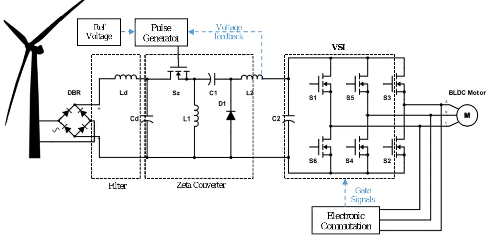
The Brushless DC motor is the ideal choice for the applications that require high reliability, high efficiency and low maintenance [12]. Being a brushless motor, BLDC motor are high performance low maintenance motor capable of providing large amounts of torque and speed performance characteristics. Conventionally a single phase BLDC motor is fed from an AC main through a diode bridge rectifier (DBR) followed by a DC capacitor and a VSI as shown in Fig. 1. Due to uncontrolled charging of the DC capacitor, pulsed AC currents are produced which affect the power factor and in turn result in power quality disturbances. In order to drive the BLDC motor with power quality improvement it needs PFC converter topology among various available topologies [9].
The basic DC-DC converters such as buck, boost and buck-boost have their intrinsic limitations when used for both active PFC and voltage regulation.
Among the new classes of DC-DC converters CUK, SEPIC and Zeta, in the proposed model a Zeta converter is used for active PFC and voltage regulation, having advantages of being naturally isolated structure, it can operate as both step up and step down voltage converter and having only one stage processing for both voltage regulation and PFC [6]. It also facilitates the soft starting of BLDC motor unlike a boost converter which habitually steps up the voltage level at its output, not ensuring soft starting [1].
Unlike a classical buck-boost converter [3], the zeta converter has a continuous and ripple free output current. Although consisting of the same number of components as a Cuk converter [2],
The zeta converter operates as non-inverting buck–boost converter unlike an inverting buck–boost and Cuk converter.
Fig. 1 Conventional wind-fed BLDC motor drive
II. CONFIGURATIONOFPROPOSEDSYSTEM
The structure of the proposed wind powered BLDC motor drive employing zeta converter is shown in Fig. 2. The proposed system consists of (left to right) an AC source from the wind turbine, a diode bridge rectifier (DBR), filter, zeta converter, a VSI and a BLDC motor. A pulse generator provides gate signal to the switch Sz of zeta converter. Electronic commutation drives the VSI switches.
Fig. 2 Proposed BLDC motor drive system
III.OPERATIONOFPROPOSEDSYSTEM
The wind turbine generates the electrical power demand of the BLDC motor. The electrical power is delivered to BLDC motor from the source after two conversions through a DBR, zeta converter and VSI as shown in Fig. 2. The zeta converter works under Continuous Conduction Mode (CCM). Initially when the zeta converter switch Sz is turned ON the diode D1 is reverse biased, the inductors L1 and L2 starts charging and capacitor C1 starts discharging. When Sz is turned OFF the diode D1 starts conducting, the inductors L1 and L2 starts discharging through the closed circuit formed by the diode and capacitor C1 starts charging. The zeta switch Sz is switched ON ensuring CCM is achieved. The zeta switch Sz is controlled by a pulse generator which compares
DBR
VSI
Pulse Generator
Voltage feedback
VSI
Zeta Converter Filter
Electronic Commutation
Gate Signals
[image:2.612.68.552.374.611.2]reference voltage and voltage feedback from the output of the zeta converter and produces necessary switching pulses. By changing the reference voltage, the speed of the motor is varied.
The VSI converts the dc output of the zeta converter into ac supply to drive the BLDC motor. The VSI is operated through a electronic commutation assisted by back EMF. Since the positions sensors are avoided and back EMF is used the switching losses are eliminated and the motor is driven efficiently.
IV.DESIGNOFPROPOSEDSYSTEM
The proposed zeta converter is designed for BLDC motor with main consideration on PFC. The zeta converter is designed for the parameters shown in Table 1. Due to change in wind speeds the input AC voltage can vary from 10V to 14V. The instantaneous value of duty ratio is expressed as
D = Vdc Vdc+Vac The minimum value of input inductor L1 for CCM is expressed as
L1 =VdcDT
∆Iac =
10*0.629*50*10-6
0.5*5 = 125.8mH
TABLE I DESIGN PARAMETERS
Input AC Voltage Vac 12V
Output DC Voltage Vdc 24V
Output Power P 50W
Switching Frequency fs 20KHz
The minimum value of output inductor L2 for CCM is expressed as
L2 =VacDT ∆Iac
=24*0.629*50*10 -6
0.5*5*1.414 = 213.5μH The value of intermediate energy transfer capacitor C1 is calculated as
C1 = TP
2{∆(Vdc+Vac)}(Vdc+Vac)
= 50*10
-6 *50
2{0.3(24+14*1.414)}(24+14*1.414)= 2.17μF The value of output capacitor C2 is derived as
C2 = Idc
2ω∆Vdc
= 2.083
2*2*π*20*103*0.3*24=1.15μF
The input filter design is very important for maintaining low harmonic distortion at the input ac mains [7]. The maximum filter capacitance is expressed as
Cd =Idctanθ 2πfsVdc
= 2.083*tan1
2*π*20*103*24= 49.6nF
The filter inductor to maintain low ripple is calculated as
Ld = 1 4π2fs2Cd=
1
4*π2* 20*103 2
*49.6*10-9
= 1.27mH
V. CONTROLOFPROPOSEDSYSTEM
then modulated using a PID controller and feed to the PWM generator which produces necessary commutation signals for Sz. Another commutation circuit is used to control the switching of the VSI. Conventionally a rotor position sensor is used as a feedback to the commutation circuit to determine the position and commute switches of the VSI appropriately as shown in Table 2. In the proposed system we use back EMF method to determine the position thus eliminating sensors. Back EMF is proportional to magnetic flux times speed and position is a function of magnetic flux. This method consists of comparing the back EMF of different phase and detecting zero crossing points. Once the zero crossing points are detected appropriate switches are triggered after a delay. When the speed varies, the winding characteristics may fluctuate, resulting in variation of back EMF. In such a situation, the DSP has complete control over the determination of zero crossing point. Also, digital filters are implemented to filter out the high frequency switching noise components from the back EMF signal. The commutation algorithm used is the standard BLDC control algorithm. The commutation occurs 30 electrical degrees after the back EMF zero crossing. Due to easy programmability of the microcontroller, the system has much flexibility to operate the motor.
TABLE II
SWITCHING STATES FOR COMMUTATION OF THE BLDC MOTOR
Rotor Position Switching States
S1 S2 S3 S4 S5 S6
0 - 60 1 0 0 1 0 0
60 - 120 1 0 0 0 0 1
120 - 180 0 0 1 0 0 1
180 - 240 0 1 1 0 0 0
240 - 300 0 1 0 0 1 0
300 – 360 0 0 0 1 1 0
[image:4.612.46.554.413.655.2]VI.SIMULATIONANDHARDWAREOFPROPOSEDSYSTEM
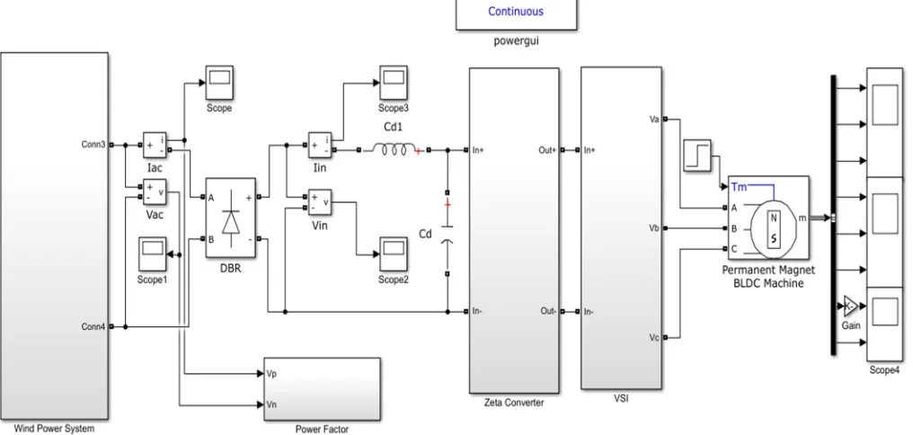
Fig. 3 Simulink model of the proposed BLDC motor drive system
Fig. 4 Simulink model of the wind power system
[image:5.612.136.492.309.493.2]After the wind power system, there is an ac to dc converson system namely DBR. Here a 12V ac supply is converted and the dc output is fed through a filter circuit and fed to the zeta converter shown in Fig. 5. The unregulated dc supply is passed through the circuit and depending on the reference voltage of the control circuit it is either bucked or boosted and a regulated dc supply is obtained.
Fig. 5 Simulink model of the zeta converter
The simulation circuit drives a 24V BLDC motor, hence the supply voltage is boosted by the zeta converter to 24V which is then fed to a VSI.
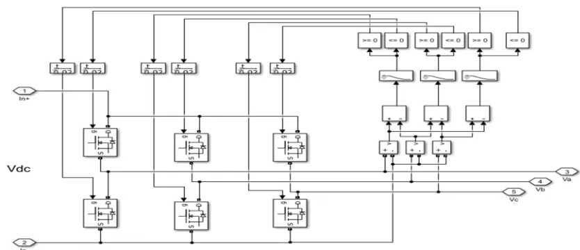
[image:5.612.95.512.535.715.2]The VSI implementing back EMF control method is shown in Fig. 6. The dc supply is then converted to ac and fed to the BLDC motor.
Fig. 7 Ac output of the Simulink wind power system
[image:6.612.68.560.299.495.2]Fig. 7 shows the output of the wind power system for changing wind speeds. The simulation was done for 14m/s to 7 m/s and we can see the change in voltage of the wind turbine.
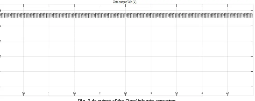
Fig. 8 dc output of the Simulink zeta converter
[image:6.612.64.552.547.717.2]The ac supply shown in Fig. 7 is fed to zeta converter through a DBR which is then boosted to around 24V as shown in Fig. 8, where we can observer that change in wind speed is well regulated by the zeta converter to produce steady output.
Fig. 10 Back EMF of BLDC motor
Fig. 11 Speed and Torque of BLDC motor
[image:7.612.102.518.402.710.2]Fig 9,10 and 11 shows the stator current, back emf, speed and torque obtained from the BLDC. Fig 12 shows the power factor obtained for the designed system. We can observe that a near unity power factor is obtained using this system.
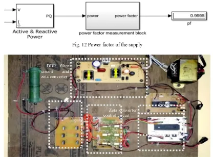
Fig. 12 Power factor of the supply
Fig. 13 Hardware setup of the proposed system DBR, filter
circuit and
zeta converter
The proposed system is implemented in hardware as shown in fig. 13. From top right, 12V ac supply, which is based through a DBR and then fed to the zeta converter. Control circuits of zeta converter and VSI uses PIC16F877A micro-controller. Mosfet P55N is used as switch in zeta converter and VSI. Optocoupler TL250 is used to provide necessary isolation for VSI and zeta converter. A three phase BLDC motor of Telco make 24V, 70W motor is used in the hardware setup. The output dc link voltage has been controlled and correspondingly speed change has been observed. The PF remains nearby unity and the power quality of the proposed PFC drive is improved.
VII. CONCLUSIONS
The wind powered BLDC motor drive using zeta converter with PFC has been proposed and its suitability has been demonstrated using MATLAB simulation and hardware implementation. The proposed system has been designed and modeled appropriately to accomplish the desired objectives. The results have shown that changing wind speed is well modulated by the zeta converter to produce steady output voltage. The speed of BLDC motor has been found proportional to the DC link voltage, so by varying the dc link voltage different speed can be achieved hence a smooth speed control is obtained. Near unity power factor has been observed, hence improved power quality is achieved.
REFERENCES
[1] B. Singh and R. Kumar, “BLDC Motor-Driven Solar PV Array-Fed Water Pumping System Employing Zeta Converter” IEEE Trans. Ind. App., vol. 52, no. 3, pp. 2315–2322, Jun. 2016.
[2] A. H. El Khateb, N. Abd. Rahim, J. Selvaraj, and B. W. Williams, “dc-to-dc converter with low input current ripple for maximum photovoltaic power extraction,” IEEE Trans. Ind. Electron., vol. 62, no. 4, pp. 2246– 2256, Apr. 2015
[3] R. Kumar and B. Singh, “Buck–boost converter fed BLDC motor drive for solar PV array-based water pumping,” in Proc. IEEE Int. Conf. Power Electron. Drives Energy Syst. (PEDES), Dec. 16–19, 2014, pp. 1–6.
[4] D. D. C. Lu and Q. N. Nguyen, “A photovoltaic panel emulator using a buck–boost dc/dc converter and a low cost micro-controller,” Solar Energy, vol. 86, no. 5, pp. 1477–1484, May 2012
[5] P. Damodharan and Krishna Vasudevan “Sensorless Brushless DC Motor Drive Based on the Zero-Crossing Detection of Back Electromotive Force (EMF) from the Line Voltage Difference,” IEEE Trans. Power Electron. , vol. 25, no. 3, pp. 661–668, Sep. 2010.
[6] A. Singh, B.P. Singh and S. Dwivedi, “AC-DC Zeta converter for power quality improvement in direct torque controlled PMSM drive,” Journal of Power Electron., vol. 6, no. 2, pp.146-162, Apr.2006.
[7] V. Vlatkovic, D. Borojevic, and F. C. Lee, “Input filter design for power factor correction circuits,” IEEE Trans. Power Electron. , vol. 11, no. 1, pp. 199–205, Jan. 2005.
[8] T.-H. Kim and M. Ehsani, “Sensorless control of BLDC motors from near-zero to high speeds,” IEEE Trans. Power Electron., vol. 19, no. 6, pp. 1635–1645, Nov. 2004.
[9] B. Singh, B. N. Singh, A. Chandra, K. Al-Haddad, A. Pandey, and D. P. Kothari, “A review of single-phase improved power quality ac–dc converters,” IEEE Trans. Ind. Electron., vol. 50, no. 5, pp. 962–981, Oct. 2003.
[10] D.C. Martins, “Zeta Converter Operating in Continuous Conduction Mode Using the Unity Power Factor Technique”, in Proceedings of IEE PEVSD’96, 1996, pp.7-11.