894
©IJRASET: All Rights are Reserved
Seismic Retrofitting by Adding a Shear Wall
Shubham Subhash Chaudhary1, Prof S. R. Parker2 1
PG Student, 2Head of Department, Department of Civil Engineering, AISSMS COE Pune - 411001, India.
Abstract: Seismic retrofitting is strengthening of existing structures in order to make them more resistant to seismic activity and ground motion due to earthquake. Considering seismic demand of structures with earthquake near metropolitan and urban areas, the need of seismic retrofitting should be well satisfied. For serving this purpose seismic retrofitting by adding a shear wall is considered for study, in which G+5 storey building is taken for analysis with and without shear wall. Modeling and analysis of G+5 steel model is carried out in SAP2000. For validation purpose , model is tested on shake table. Present study shows that structure becomes stiff by addition of shear wall and reduces displacement.
Keywords: Seismic retrofitting, shear wall, SAP2000, steady state analysis, time history analysis, shake table.
I. INTRODUCTION
Seismic retrofitting is the technique in which the strengthening of existing structures is done to make it resistant from seismic activity such as ground motion due to earthquake , soil failure etc. Following methods listed below are used to satisfy this purpose. In retrofitting, elements or components such as shear wall, bracing etc are either added or subtracted in order to maintain structural stability and strength. In above context added means addition of shear wall or bracing and subtraction means mass reduction in the form of a storey or a component such as beam column etc.
A. Methods
There are two main techniques of retrofitting:
1) Global Retrofitting Techniques
a) Adding shear wall
b) Adding bracing
c) Mass reduction
d) Wall thickening
e) Base isolation
f) Mass dampers
2) Local Retrofitting Techniques
a) Jacketing of Beam
b) Jacketing of Columns
c) Jacketing of Beam and Column Joints
d) Jacketing of Individual footing
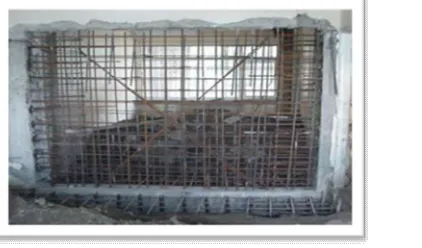
B. Retrofitting By adding shear wall
[image:1.612.216.427.598.722.2]Retrofitting by adding shear wall is frequently used for non ductile reinforced concrete building frames. In this method the element added may be pre-casted or cast in-situ. Element added is placed at the exterior of building in order to avoid interior molding.
895
©IJRASET: All Rights are Reserved
II. LITERATUIRE
Asokan A. (2004), have studied seismic analysis and retrofit of existing multistoried buildings in India – an overview with a case study. In this paper they have used various methodologies in order to assess seismic vulnerability of reinforced concrete residential and commercial buildings and to propose retrofit measures for the structurally deficient buildings.[01]
Giuseppe oliveto and Massimo Marlette (2005), have studied traditional and innovative techniques of retrofitting and identified their weak points. Methods such as base isolation, energy dissipation devices and philosophies of seismic retrofitting are reviewed.[02] K. Galal and H. El-Sokkary(2008), worked on recent advancement in retrofitting of shear wall. With change in advancement in design of shear wall day by day, they tried to make advancement in retrofitting technique accordingly. That is they tried to upgrade the methods of retrofitting of RC shear wall. The objective of this paper is to provide a state-of-the-art on the recent advancements and challenges in the area of retrofit of RC shear walls. [03]
Kirtika Gupta , Abhishek Kumar and Mohd. Afaque Khan(2017) have presented a review paper on seismic retrofitting. In this paper they performed the software analysis on bare frame with addition of shear wall suing STAAD Pro V8i and found that the capacity of structure with shear wall increases.[04]
Hasan Kaplan, Salih Yilmaz, Nihat Cetinkaya And Ergin Atimtay(2017) have presented the work on strengthening of RC structure
with exterior shear wall. They have performed the experimental analysis on shear wall using reverse cyclic loading test and then performed retrofitting analysis. They found that post attached shear wall is monolithic in nature and also discussed the design consideration of shear wall.[05]
Various Seismic retrofitting techniques are studied in past research by the authors. This research work, mainly focuses on retrofitting by adding a shear wall, in order to increase the performance of the building in earthquake prone areas
III.METHODOLOGY
A. Model Description
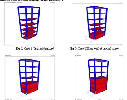
Following Different Cases are Studied as shown in figures below:
Fig. 2: Case 1 (Framed structure) Fig. 3: Case 2(Shear wall at ground storey)
[image:2.612.87.524.371.716.2] [image:2.612.331.509.376.532.2]
896
©IJRASET: All Rights are Reserved
[image:3.612.189.426.295.505.2]
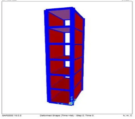
Fig. 6 : Case 5(Shear wall upto third storey) Fig. 7 : Case 6(Shear wall upto fourth storey)
Fig. 8 : Case7(Shear wall upto top storey)
B. Method of Analysis
1) Models of G+5 storey steel structural in SAP2000 is prepared and modal analysis carry out.
2) Steady-state analysis of model in SAP2000 for the same obtained modal frequency and recording lateral top displacement.
3) Shake table test on the same structure for obtained modal frequency is performed in laboratory and lateral top displacement is recorded with the help of data translation system.
4) Comparison of SAP2000 and shake table results is done after performing the test and analysis. Time series data is obtained for the same modal frequency from installed horizontal shake table for the same model.
5) Time history analysis is carried out on bare frame model in SAP2000 and lateral displacements at each storey is recorded.
6) Similarly models of bare frame with shear wall as shown in another cases other than case 1 are prepared.
7) Time history analysis of bare frame with above mentioned arrangement of shear wall in SAP2000 and recording lateral displacements at each storey.
897
©IJRASET: All Rights are Reserved
IV.RESULTS
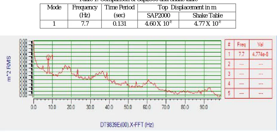
[image:4.612.75.539.124.345.2]1) Following Are Results Obtained From Steady State Analysis For Modal Frequency For 1st Mode
Table 1: Comparison of Sap2000 and Shake table
Mode Frequency
(Hz)
Time Period (sec)
Top Displacement in m
SAP2000 Shake Table
1 7.7 0.131 4.60 X 10⁻⁸ 4.77 X 10⁻⁸
Fig. 9: Top Displacement of Structure recorded on shake table
[image:4.612.127.484.462.719.2]2) Time History Analysis of G+5 storey Structure with Shear wall at Varying Number of Storey in SAP2000: After validation of steady state analysis in SAP and on shake table,G+5 Storey structure with shear wall at different storey is modeled in SAP2000 and time history analysis is performed on the same model for which time history is taken from steady state. The applied time history is obtained by data translation system and time series data is collected. Maximum top displacement , velocity and acceleration of these structure is recorded and tabulated in tables below with graph.
Table 2: Displacement in mm
Case 1 Case 2 Case 3 Case 4 Case 5 Case 6 Case 7
G.F. 0.76 9.40x10⁻⁵ 6.46x10⁻⁵ 5.40x10⁻⁵ 9.75x10⁻⁵ 4.00x10⁻⁵ 1.47x10⁻⁴
G+1 1.55 0.53 2.08x10⁻⁴ 1.72x10⁻⁴ 3.14x10⁻⁴ 1.30x10⁻⁴ 4.60x10⁻⁴
G+2 2.11 0.99 0.41 3.40x10⁻⁴ 6.19x10⁻⁴ 2.6x10⁻⁴ 8.90x10⁻⁴
G+3 2.60 1.36 0.70 0.29 1.00x10⁻³ 4.1x10⁻⁴ 1.39x10⁻³
G+4 2.78 1.59 0.89 0.52 0.48 6.1x10⁻⁴ 1.92x10⁻³
G+5 3.38 1.72 1.04 0.64 0.76 0.18 2.46x10⁻³
898
[image:5.612.138.472.86.408.2]©IJRASET: All Rights are Reserved
Table 3: Velocity in mm/s
Model Case 1 Case 2 Case 3 Case 4 Case 5 Case 6 Case 7
G.F. 37.30 3.38x10⁻³ 4.10x10⁻³ 4.47x10⁻³ 1.06x10⁻² 6.70x10⁻³ 2.76x10⁻²
G+1 70.70 23.50 1.24x10⁻² 1.39x10⁻² 3.43x10⁻² 2.18x10⁻² 8.66x10⁻²
G+2 93.60 39.40 27.60 2.75x10⁻² 6.76x10⁻² 4.36x10⁻² 0.16
G+3 99.90 46.60 41.20 24.30 0.10 7.02x10⁻² 0.26
G+4 103.1 54.40 43.00 42.80 53.00 0.20 0.36
G+5 111.8 66.10 57.60 52.60 87.80 30.70 0.46
[image:5.612.141.475.441.713.2]Fig. 11: Graph of Time Vs Velocity
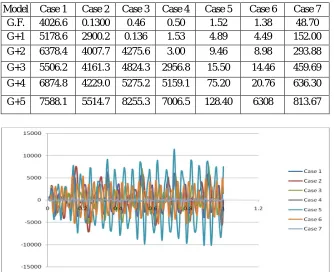
Table 4: Acceleration in mm/s2
Model Case 1 Case 2 Case 3 Case 4 Case 5 Case 6 Case 7
G.F. 4026.6 0.1300 0.46 0.50 1.52 1.38 48.70
G+1 5178.6 2900.2 0.136 1.53 4.89 4.49 152.00
G+2 6378.4 4007.7 4275.6 3.00 9.46 8.98 293.88
G+3 5506.2 4161.3 4824.3 2956.8 15.50 14.46 459.69
G+4 6874.8 4229.0 5275.2 5159.1 75.20 20.76 636.30
G+5 7588.1 5514.7 8255.3 7006.5 128.40 6308 813.67
899
©IJRASET: All Rights are Reserved
V. CONCLUSIONS
In the present study, time history analysis is carried out on multi-storeyed building with or without shear wall. The conclusions that can be drawn from the above results are as follows:
A. From table 2 we come to know that Case 1(Bare frame) shows larger lateral displacement than other cases.
B. Case 7 shows smaller lateral displacement than other cases.
C. Lateral displacements decreases as we go on adding shear wall floor by floor.
D. With displacement, velocity and acceleration also decreases as shown in graphs above.
VI.ACKNOWLEDGMENT
The author would like to thank Dr. S. R. Parekar for providing the continuous guidance. The author is alsoindebted to them. He records thankfulness to them for their motivational support and valuable suggestions for presenting this study work.
REFERENCES
[1] Amlan K. Sengupta , Chemuru Srinivasulu Reddy , Badari Narayanan V T And Asokan A (2004) "Seismic analysis and retrofit of existing multistoreyed buildings in india – an overview with a case study" , World Conference on Earthquake Engineering
[2] Giuseppe Oliveto And Massimo Marletta (2005) "Seismic retrofitting of reinforced concrete buildings using traditional and innovative techniques", Journal of Earthquake Technology, Paper No. 454, Vol. 42.
[3] K. Galal And H. El-Sokkary(2008),"Recent advancements in retrofit of rc shear walls", World Conference on Earthquake Engineering .
[4] Hasan Kaplan Salih Yilma , Nihat Cetinkaya And Ergin Atimtay (2011),"seismic strengthening of RC structures with exterior shear walls", Indian Academy of Sciences.
[5] M.A. Ismaeil ,A.E.Hassaballa(2013),"Seismic retrofitting of a rc building by adding steel plate shear walls)", Journal of Mechanical and Civil Engineering (IOSR-JMCE) e-ISSN: 2278-1684,p-ISSN: 2320 to 334X, Volume 7, Issue 2.