Hardware Co-simulation For Video Processing Using
Xilinx System Generator
T. Saidani , D. Dia, W. Elhamzi, M. Atri and R. Tourki
Abstract— The use of rapid prototyping tools such as MATLAB-Simulink and Xilinx System Generator becomes increasingly important because of time-to-market constraints. This paper presents a methodology for implementing real-time DSP applications on a reconfigurable logic platform using Xilinx System Generator (XSG) for Matlab. The methodology aims to improve the design verfication efficiency for such complex system. It presents an architecture for Color Space Conversion (CSC) RGBTOYCbCr for video processing using Xilinx System Generator. The design was implemented targeting a Spartan3 device (3S200PQ208) then a Virtex II Pro (xc2vp7-6ff672). Obtained results are discussed and compared with an other architecture. The conversion method has been verified successfully with no visually perceptual errors in the transformed images.
Index Terms—Codesign Environment, FPGA Board, Rapid
Prototyping, Video processing, Xilinx System Generator.
I. INTRODUCTION
Video processing and computer vision methods become increasingly important not only in the industrial applications but also in our daily life [1]. Video processing generally exploits tasks with very high computational demands. Such tasks can be handled by the standard processors and computers or by computers connected to the computational networks [1]. However, such approach is not always suitable that’s why specialized hardware solutions based on digital signal processors (DSP) or a field programmable gate arrays (FPGA) are usually used in embedded systems [2, 8]. Xilinx System Generator allows the design of hardware system starting from a graphical high level Simulink environment [3, 8]. System Generator extends the traditional Hardware Description Language (HDL) design providing graphical modules, and thus does not require a detailed knowledge of this complex language. The Simulink graphical language allows an abstraction of the design through the use of available System Generator blocks and subsystems [8]. This reduces the time necessary between the control design derivations and hardware implementation. In addition, the software provides for the hardware simulation and hardware-in-the-loop verification, referred to as hardware co-simulation [2, 3], from within this environment. This methodology provides easier hardware verification and implementation compared to HDL based approach. The Simulink simulation and hardware-in-the loop
Manuscript received March 23, 2009.
Authors are with the EµE Laboratory, Faculty of Sciences, Monastir, 5000, Tunisia (corresponding author M. Atri:+216 73 501785; fax: :+216 73 501785; e-mail: [email protected]).
approach presents a far more cost efficient solution than other methodologies. The ability to quickly and directly realize a control system design as a real-time embedded system greatly facilitates the design process.
The remainder of this paper is divided into six sections. After introducing, a description of Design methodology for implementation on FPGA with Xilinx System Generator is presented, section 3 presents a study case which is Color Space Conversion Application. In Section 4, experimental results and software performances are detailed. Section 5 shows some discussion and comparison. This paper is concluded in Section 6.
II. DESIGN METHODOLOGY FOR IMPLEMENTATION ON
FPGA WITH XILINX SYSTEM GENERATOR
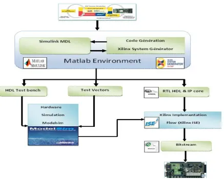
Efficient rapid prototyping system requires a development environment targeting the hardware design platform. The used tools are MATLAB R2007a with Simulink from MathWorks [3, 4], System Generator 10.1 for DSP and ISE 10.1 from Xilinx present such capabilities (figure 1). Although the Xilinx ISE 10.1 [2, 4] foundation software is not directly utilized, it is required due to the fact that it is running in the background when the System Generator blocks are implemented. The System Generator [2] environment allows for the Xilinx line of FPGAs to be interfaced directly with Simulink. In addition there are several cost effective development boards available on the market that can be utilized for the software design development phase.
MATLAB is an interactive software for numerical computations that simplifies the implementation of linear algebra routines. Powerful operations can be performed by using the provided MATLAB commands. Simulink [2, 8] is an additional MATLAB toolbox that provides for modeling, simulating and analyzing dynamic systems within a graphical environment. The software allows for both modular and hierarchical models to be developed providing the advantage of developing a complex system design that is conceptually simplified.
Xilinx System Generator is a MATLAB-Simulink based design tool for Xilinx’s line of FPGAs. Complex digital circuits have been developed using multiple Hardware Description Language (HDL) modules. Because of the abstraction level is very low within the HDL environment, the difficulty increases as the design becomes more complex [4].
Figure 1: Design methodology with Xilinx System Generator
implement digital designs in a FPGA or CPLD target device [1,2]. The synthesis of these modules creates netlist files which serve as the input to the implementation module. After generating these files, the logic design is converted into a physical file that can be downloaded on the target device.
III. STUDY CASE:COLOR SPACE CONVERSION RGB TO
YCBCR
A. Overwiew
Color Space Conversion (CSC) [5, 6] is an important application in image and video processing systems. CSC has been implemented in software and various kinds of hardware. Hardware implementations can achieve a higher performance compared to software-only solutions. Application specific integrated circuits (ASICs) are efficient and have good performance. However, they lack the programmability of devices such as field programmable gate arrays (FPGAs) [7, 8].
Many video applications require converting video and image content from one color space to another [10, 13, 14]. Images and motion images (video) have utilized a wide variety of color spaces including: RGB, YCrCb, HSI, and other formats to represent the colors within the image [15]. Each of
different video equipment will adopt different color space encodings. Interoperability between such equipment often requires a device to convert the output of one video device in a given color space to the color space needed as input for the down stream device. Some examples of color space conversion are the converting of the RGB video output from a computer VGA card to YCrCb input on a TV monitor [5, 15]. The opposite conversion path is also common where a video device such as a DVD player outputs YCrCb and the video needs to be converted to RGB to drive a monitor [15].
B. YCbCr Color Model
YCbCr color model also belongs to the family of television transmission color models. In this color model, the luminance component is separated from the color components. Component (Y) represents luminance, and chrominance information is stored as two color-difference components. Color component Cb represent the difference between the blue component and a reference value and the color component Cr represents the difference between the red component and a reference value. The following conversion is used to segment the RGB image into Y, Cb and Cr components: The conversion matrix can be expressed as in equation (1) [15].
= * +
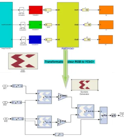
Among all the color models found, YCbCr seems to be better for skin detection since the Colors in YCbCr are specified in terms of luminance (Y channel) and chrominance (Cb and Cr channels). The main advantage of converting the image from RGB color model to the YCbCr color model is the influence of luminance can be removed during our video processing. Figure 2 shows the conversion of a RGB color model in to a YCbCr color model implemented with the function rgb2ycbcr from Matlab.
IV. IMPLEMENTATION RESULTS, SIMULATION AND
COMPARISONS
[image:3.595.323.529.265.495.2]A. Hardware Co-simulation
Figure 3 shows the model that uses the top level HDL module and its Xilinx blokset for RGB to Y component. This model can be used for co-simulation. Once the design is verified, a hardware co-simulation block can be generated. and then will be used to program the FPGA for the CSC design implementation. Figure 4 shows the model with the hardware co-simulation block. The bitstream download step is performed using a JTAG cable.
B. Simulation
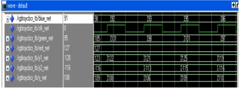
After the co-simulation step the VHDL codes were automatically generated from the System Generator block sets. Behavioral and post simulation are supported by Mentor Graphics ModelSim tool (Figure 5).
[image:3.595.54.279.342.387.2]RGB Color YCbCr Color
Figure 2: Matlab implementation for rgb2ycbcr
Figure 3:System Generator project for simulation
[image:3.595.330.541.532.700.2]Figure5. Simulation results of the VHDL RGB to YCbCR conversion
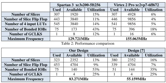
The VHDL codes were then synthesized using Xilinx ISE 10.1i and targeted for Xilinx Spartan3 and Virtex II Pro family [2]. The optimization setting is for maximum clock speed. Table 1 details the resource requirements of the design. Note that in practice, additional blocks are needed for input/output interfaces, and synchronization.
The HDL-based circuit design flow is completed with the Xilinx ISE tool to perform synthesis, implementation, place & route and device programming for the whole design. For the arithmetic units, unsigned pipeline integer divider with both quotient and remainder output are parameterized and generated by Xilinx Core Generator tool [4, 8]. Multiplication uses the embedded multiplier in the hardware. The target FPGA chip is Xilinx Virtex II Pro xc2vp7-6ff672 and Spartan 3 xc3s200-5 ft256. During the Simulink-to-FPGA design flow, circuit modeling is built up with Simulink basic blocks and Xilinx specified blocks. Input and output data are combined with Matlab workspace, which is convenient to convert number format and debug. Figure 6 shows the software and hardware simulation for the CSC design for the input image.
V. DISCUSSION
To provide a proper performance evaluation, the implemented CSC architecture using low cost available Spartan-II development system with Xilinx chip 2S200PQ208. The properties of other designs along with ours are listed in Table 2. As seen from this table, the design ofthe CSC proposed by
[7] requires 380 CLB on the basis clock rate of 55.159 MHz. On the other hand, our resulting architecture spent about 323
CLB with a working frequency up to 83.271MHz. Obviously, our proposed architecture has lower complexityand improved efficiency in area, thus providing a good choice in terms of low-cost hardware.
From the development of FPGA technology, the methodology challenges the update of various EDA tools [13]. Based on the standard development flow, initial efforts have been transferred to high-level design and synthesis. There are many conversion tools such as C-to-FPGA, Stateflow diagram to VHDL Matlab-to-FPGA. The features of Simulink/Xilinx System Generator-to-FPGA [2, 3] flow can be discussed as follows.
• Fast time-to-market for DSP development. With the assistance of specified DSP blocks for FPGA, the Simulink/Xilinx System generator-to-FPGA flow can greatly shorten the development cycle from algorithm to hardware [4].
• Friendly graphics interface. Although the schematic entry is also a GUI interface, the Simulink is easier to organize input data and much convenient to observe output in many ways [8].
• Flexible modeling and simulation. The design can be well organized into hierarchical modules and easy to be combined with other entry method for design decision and convenient to debug and simulation.
VI. CONCLUSION AND FUTUR WORK
Xilinx system generator is a very useful tool for developing computer vision algorithms. It could be described as a timely, advantageous option for developing in a much more comfortable way than that permitted by VHDL or Verilog hardware description languages (HDLs). The purpose of this paper was to demonstrate the use of System Generator to design a system RGB to YCbCr conversion (CSC) for video processing. This design is implemented in the device Spartan 3 (xc3s200-5ft256) and Virtex II Pro (Virtex 2 Pro xc2vp7-6ff672). The implemented CSC architecture using low cost available Spartan-II development system with Xilinx chip 2S200PQ208 has 83.271 MHz maximum frequency and uses 323 CLB slices with 13% utilization.
[image:4.595.47.286.130.219.2]Future works include the use of the Xilinx System Generator development tools for the implementation of other blocks used in video processing like wavelet transform, motion estimation
Figure 6: Outputs from different implementations
Software Y component
Lena (512*512) RGB test image
Table 1: FPGA resources used in the implementation for the CSC
Spartan 3 xc3s200-5ft256 Virtex 2 Pro xc2vp7-6ff672 Used Available Utilization Used Available Utilization Number of Slices 307 1920 15% 307 4928 6%
Number of Slice Flip Flop 443 3840 11% 446 9856 4%
Number of 4 input LUTs 545 3840 14% 541 9856 5%
Number of Bonded IOBs 75 173 43% 75 396 18%
Number of GCLKS 1 8 12% 1 16 6%
Maximum Frequency 129.721MHz 155.063MHz
Table 2: Performance comparison
Our Design Design [7]
Used Available Utilization Used Available Utilization
Number of Slices 323 2352 13% 380 2352 16%
Number of Slice Flip Flop 453 4704 9% 339 4704 7%
Number of Bonded IOBs 75 140 53% 51 144 35%
Number of GCLKS 1 4 25% 1 4 25%
Maximum Frequency 83.271MHz 55.159MHz
REFERENCES
[1] P. Zemcik, “Hardware Acceleration of Graphics and Imaging Algorithms Using FPGAs,” in SCCG ’02: Proceedings of the 18th Spring Conference On Computer Graphics, (New York, NY, USA), pp. 25–32, ACM Press, 2002.
[2] Xilinx System Generator User's Guide, www. Xilinx.com.
[3] Inc., T. M.: Embedded Matlab Language User Guide. The MathWorks Inc., 2007.
[4] Ownby, M.; Mahmoud, W.H. “A Design Methodology for Implementing DSP with Xilin System Generator for Matlab", in IEEE International Symposium on System Theory, 2003,pp. 404- 408. [5] D. Han, “A cost effective color gamut mapping architecture for digital tv
color reproduction enhancement,” IEEE Transactions on Consumer Electronics, vol. 51, no. 1, pp. 168–174, 2005.
[6] M. Bilal and S. Masud, “Efficient color space conversion using custom instruction in a risc processor,” in IEEE International Symposium on Circuits and Systems, 2007,pp. 1109 1112.
[7] Sapkal, A.M.; Munot, M.; Joshi, M.A. “R' G'B' to Y'CbCr Color Space Conversion Using FPGA” Wireless, Mobile and Multimedia Networks, 2008. IET International Conference on Digital Object Identifier Volume , Issue , 11-12 Jan. 2008 Page(s):255 – 258
[8] J.C.Moctezuma, S.Sanchez, R.Alvarez, A. Sánchez “ Architecture for filtering images using Xilinx system generator” World Scientific Advanced Series In Electrical And Computer Engineering, Proceedings of the 2nd WSEAS International Conference on Computer Engineering and Applications. pages 284-289.2008
.
[9] L. V. Agostini, I. S. Silva, and S. Bampi, “Parallel color space converters for JPEG image compression,” Microelectronics Reliability, vol. 44, no. 4, pp. 697–703, April 2004.
[10] M. Sima, S. Vassiliadis, S. Cotofana, and J. T. J. van Eijndhoven, “Color space conversion for MPEG decoding on FPGA-augmented trimedia processor,” in Proceedings. IEEE International Conference on Application-Specific Systems, Architectures, and Processors, Jun. 2003, pp. 250–259.
[11] P. Kuchi, P. Gabbur, P. S. Bhat, and S. David, “Human face detection and tracking using skin color modelling and connected component operators,” The IETE Journal of Research, Special issue on Visual Media Processing, May 2002.
[12] M. Bilal and S. Masud, “Efficient color space conversion using custom instruction in a risc processor,” in IEEE International Symposium on Circuits and Systems, 2007,pp. 1109 1112.
[13] D. Han, “Real-time color gamut mapping method for digital tv display quality enhancement,” IEEE Transactions on Consumer Electronics, vol. 50, no. 2, pp. 691– 698, 2004. A. Albiol, L. Torres, and E. J. Delp, “An unsupervised color image segmentation algorithm for face detection applications,” in Proceedings. 2001 International Conference on Image Processing, vol. 2, 2001, pp. 681–684 vol.2.
[14] A. Albiol, L. Torres, and E. J. Delp, “An unsupervised color image segmentation algorithm for face detection applications,” in Proceedings. 2001 International Conference on Image Processing, vol. 2, 2001, pp. 681–684 vol.2.