A Review of Predictive Control Techniques for
Matrix Converter Applications
M. Rivera Universidad de Talca,
Curic´o, Chile [email protected]
P. Wheeler The University of Nottingham,
Nottingham, UK [email protected]
J. Rodriguez Universidad Andres Bello,
Santiago, Chile [email protected]
B. Wu Ryerson University,
Toronto, Canada [email protected]
Abstract—Predictive control has recently emerged as a promis-ing alternative to more traditional methods for the control and modulation of power converters. This paper presents an overview of predictive control techniques applied to matrix converters. The paper highlights that predictive control strategy is a promising alternative to conventional modulator based linear control for matrix converters due to its simplicity and flexibility to include additional constraints within the control to have it suitable for different applications. In addition to describing many advantages of predictive control techniques, its limitations and weaknesses are also discussed along with some future trends and applications. Most important control aspects of predictive control are demonstrated through simulation analysis.
Index Terms—ac-ac conversion, matrix converter, predictive control, modulation schemes.
NOMENCLATURE
is Source currents [𝑖𝑠𝐴𝑖𝑠𝐵𝑖𝑠𝐶]𝑇
vs Source voltages [𝑣𝑠𝐴𝑣𝑠𝐵𝑣𝑠𝐶]𝑇
ii Input currents [𝑖𝐴𝑖𝐵𝑖𝐶]𝑇
vi Input voltages [𝑣𝐴𝑣𝐵𝑣𝐶]𝑇
io Output currents [𝑖𝑎𝑖𝑏𝑖𝑐]𝑇
vo Output voltages [𝑣𝑎𝑣𝑏𝑣𝑐]𝑇
i∗
s Source current references [𝑖∗𝑠𝐴𝑖∗𝑠𝐵𝑖∗𝑠𝐶]𝑇 i∗
o Output current references [𝑖∗𝑎𝑖∗𝑏𝑖∗𝑐]𝑇 v∗
o Output voltage references [𝑣𝑎∗𝑣𝑏∗𝑣𝑐∗]𝑇
𝐶𝑓 Input filter capacitor
𝐿𝑓 Input filter inductor
𝑅𝑓 Input filter resistor
𝑅𝐿 Load resistance
𝐿𝐿 Load inductance
I. INTRODUCTION
The matrix converter (MC) shown in Fig. 1 is a simple power conversion circuit that directly connects the𝑎𝑐-source with any arbitrary 𝑎𝑐-load without the need for large storage elements (𝑑𝑐 capacitors and inductors), making this topology suitable for many applications where weight and size are important issues. With the MC topologies, generation of output voltages of any amplitude and frequency, operation with sinu-soidal input and output current waveforms, control with unity displacement power factor, and regenerative capability are all possible. The major challenge with MCs is the commutation of current between the bidirectional switches, however this issue has been solved with multi-step commutation techniques [1], [2]. Due to many favorable characteristics and benefits, in recent years, the MCs have shown continuous and rapid
𝑖𝐴
𝑖𝐵
𝑖𝐶
𝑖𝑎 𝑖𝑏 𝑖𝑐
𝑆𝐴𝑎 𝑆𝐴𝑏 𝑆𝐴𝑐
𝑆𝐵𝑎 𝑆𝐵𝑏 𝑆𝐵𝑐
𝑆𝐶𝑎 𝑆𝐶𝑏 𝑆𝐶𝑐
𝐴
𝐵
𝐶
[image:1.595.335.513.199.390.2]𝑎 𝑏 𝑐
Fig. 1. Power circuit of conventional direct matrix converter.
development in terms of new topologies and control schemes investigation, including industrial applications with standard MC units for high and medium voltage using cascaded con-nections [3], [4].
Various modulation and control methods have been pro-posed in the literature for MCs [5]–[38]. These methods have different digital implementations and different levels of complexity, but they all have dynamic performance which is acceptable in a variety of applications. As reviewed in [39] and shown in Fig. 2, the most commonly used techniques are Venturini [5], carrier-based pulse width modulation (PWM) [7], [8], space vector modulation (SVM) [9], [10] and direct torque control (DTC) [11], [12]. Other control methods that have been applied to MCs in specific applications are fuzzy control, neural networks and genetic algorithms [40], [41]. Due to the discrete nature, intuitive approach and simplicity of MCs for real-time implementation, the predictive control has shown to be a very promising alternative to control MCs [15]–[38].
Modulation and Control Methods for Matrix Converters
Scalar Techniques
[5], [6]
Pulse Width Modulation
[7]–[10]
Direct Torque Control
[11], [12]
Direct Power Control
[13], [14]
Model Predictive Control
[15]–[38]
Other Methods
Direct Transfer Function
[5]
Scalar (Roy)
[6]
Carrier Based PWM
[7], [8]
Space Vector Modulation
[9], [10]
Predictive Current Control
[15]–[24]
Predictive Torque Control
[25]–[29]
Predictive Power Control
[30]–[33]
Predictive Voltage Control
[34]–[36]
Unity Transfer
[image:2.595.65.533.114.259.2][37], [38] [40], [41]
Fig. 2. Summary of modulation and control methods for matrix converters.
II. CONVENTIONALMODULATION ANDCONTROL
The power topology of standard direct MC is presented in Fig. 1. The circuit consists of bidirectional switches that directly connect any input line to any output line at any point in time. A harmonic filter is normally used at the input-side with the following two purposes [1], [2]:
∙ To provide a low impedance path which avoids the
generation of over-voltages due to fast commutation of currents between the bidirectional switches.
∙ To attenuate high-frequency harmonics in the input cur-rents in order to meet any relevant input power quality standards.
The operation of any MC is restricted by two constraints:
∙ The load current cannot be interrupted due to the induc-tive nature of the load.
∙ The operation of switches should not involve short cir-cuiting of any of the input lines.
These restrictions are expressed by:
𝑆𝐴𝑦 + 𝑆𝐵𝑦 + 𝑆𝐶𝑦 = 1, ∀ {𝑦=𝑎, 𝑏, 𝑐}. (1)
The relationship between input and output variables of a MC is given by:
vo = T(𝑆𝑖𝑗)vi (2)
ii = T(𝑆𝑖𝑗)𝑇 io (3)
where T(𝑆𝑖𝑗)is the instantaneous transfer matrix defined by
T(𝑆𝑖𝑗) = ⎡
⎣ 𝑆𝑆𝐴𝑎𝐴𝑏 𝑆𝑆𝐵𝑎𝐵𝑏 𝑆𝑆𝐶𝑎𝐶𝑏
𝑆𝐴𝑐 𝑆𝐵𝑐 𝑆𝐶𝑐
⎤
⎦. (4)
Equations (2) and (3) form the basis of all MC modulation methods which consist of selecting appropriate combinations of “on” and “off” switches to achieve the desired converter output voltages [1], [2].
III. PRINCIPLES OFPREDICTIVECONTROL FORMATRIX CONVERTERS
Finite control-set model predictive control (FCS-MPC), simply called MPC from here onwards, is a digital control
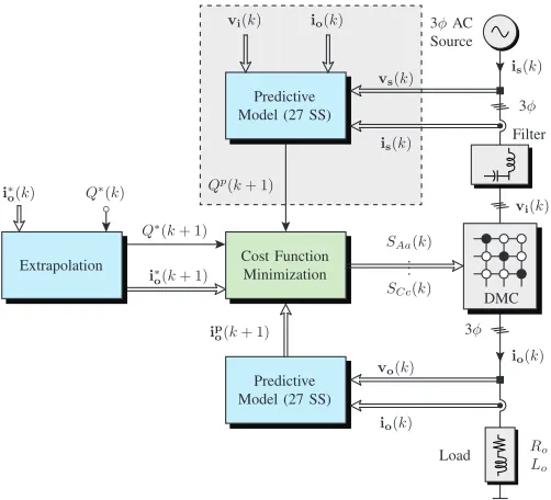
technique which has recently been applied to control the power converters. This control method utilizes a mathematical model of the controlled system in order to predict, at each sampling instant 𝑘, the system’s behavior at 𝑘+ 1. In order to select the optimal state of the power converter during each time period, a cost function is defined. This function is composed using several elements or control objectives. Each element can represent specific constraints, such as limitation of switching frequency or other nonlinearities. Constraints contain the difference between the reference and predicted values of the variables to be controlled. As an example, the predictive current control (PCC) for the direct MC (DMC) is presented in this section. The PCC scheme in Fig. 3 shows the switching state selection for a DMC, which displays the nearest references to the controlled variable at the end of each sampling period, respectively. This control approach utilizes the converter and load models in order to predict the future value of currents. A simple and representative model of the load can be expressed as:
𝑑io
𝑑𝑡 =
1
𝐿𝐿vo−
𝑅𝐿
𝐿𝐿io. (5)
Knowing the nature of the load, a first order discrete approximation allows predicting the future load current:
io(𝑘+ 1)≈𝑇𝑠vo(𝐿𝑘+ 1) +𝐿𝐿io(𝑘)
𝐿+𝑅𝐿𝑇𝑠 (6)
where 𝑇𝑠corresponds to the discretization sampling time. A cost function is defined in order to determine the error be-tween the reference currentsi∗o, and their respective predicted currents ipo, given by:
𝑔(𝑘) =∣𝑖∗
𝑎−𝑖𝑝𝑎∣+∣𝑖∗𝑏−𝑖𝑝𝑏∣+∣𝑖∗𝑐−𝑖𝑝𝑐∣ (7)
Predictive Model (27 SS)
Predictive Model (27 SS)
Cost Function Minimization Extrapolation
DMC Filter 3𝜙AC Source io(𝑘)
io(𝑘)
io(𝑘)
ip o(𝑘+ 1)
i∗
o(𝑘)
i∗
o(𝑘+ 1)
𝑆𝐴𝑎(𝑘) .. . 𝑆𝐶𝑐(𝑘)
vo(𝑘)
is(𝑘)
is(𝑘)
vs(𝑘)
vi(𝑘)
vi(𝑘)
𝑄∗(𝑘) 𝑄𝑝(𝑘+ 1)
𝑄∗(𝑘+ 1)
𝑅𝑜 𝐿𝑜 Load
3𝜙
3𝜙
𝑔=∣i∗
[image:3.595.40.291.114.342.2]o(𝑘+ 1)−ipo(𝑘+ 1)∣2+𝜆𝑞∣𝑄∗(𝑘+ 1)−𝑄𝑝(𝑘+ 1)∣2
Fig. 3. Block diagram of PCC with instantaneous input reactive power minimization for DMC.
The main differences between the topologies are in the number/arrangement of the switches, operation constraints and applications. The most important advantages of these topology variations are the increment of output voltage control range and reduction of switching frequency harmonics, losses and common-mode voltage. It is of course possible to apply the principles of MPC to any of the derived MC topologies including indirect MC (IMC) [15], [18], [21], [23], [24]. In [34]–[36], predictive controllers for a single-phase MC application (SPMCs) were proposed. The most popular of these derived MC topologies is the IMC, being implemented using predictive controllers with a variety of cost functions [15], [18], [21], [23], [24], [26], [28], [40]. In this paper, the presented examples will assume a DMC; but all the techniques can be applied to any MC topology.
IV. PREDICTIVECONTROLSTRATEGIES AND APPLICATIONS
Based on previously reported scholarly works, there are several implementations of MPC which have successfully been applied in MC applications. As indicated in Fig. 2, the most relevant techniques correspond to PCC [15]–[24] and predictive torque control (PTC) [25]–[29]. It is also possible to find some implementations of predictive reactive/active power control (PPC) [30]–[33], and predictive voltage control (PVC) [34]–[36] where an 𝐿𝐶 filter is used at the output of MC to provide a voltage source rather than a conventional load control function.
A. Basic Current Control
In this section, different PCC implementations are discussed in regards to specific applications and control objectives. The
basic PCC strategy consists in the load’s current control while reducing the instantaneous reactive power at the input side of the converter (Fig. 3). The cost function is now defined as:
𝑔(𝑘) =△io+𝜆𝑞△𝑄 (8)
where 𝜆𝑞 is the weighting factor for input reactive power minimization. By including the instantaneous reactive power minimization for the MC input it is possible to obtain unity power factor. However, it has been observed that the PCC, using the reactive power minimization term, is very sensitive to the distortion of the source voltage and resonance of the input filter [16] (before 𝑡=0.06[s]). By implementing active damping method (after𝑡=0.06[s]), it is possible to improve the performance of the system by mitigating the resonances of the input filter [16], [17]. It is also possible to force the source current to follow a sinusoidal reference value, regardless of the distortion level at the input side. The cost function for this modified scheme is defined by
𝑔(𝑘) =△io+𝜆𝑖△is (9)
where △is = ∣𝑖𝑠𝐴∗ −𝑖𝑝𝑠𝐴∣+∣𝑖∗𝑠𝐵−𝑖𝑝𝑠𝐵∣+∣𝑖∗𝑠𝐶 −𝑖𝑝𝑠𝐶∣. The results shown in Fig. 5 and in [15], [17], [23] demonstrate that by imposing a given waveform for the source current, it is possible to obtain a better performance than with an instantaneous reactive power minimization (Fig. 4), reducing the total harmonic distortion (THD) of both input and load currents.
B. Induction Motor Control
A different approach for the control of an induction machine with PCC using instantaneous reactive power minimization is presented in [20]. In this control method, the predictive stage performs PCC, while a classic control stage regulates speed, flux, and torque based on field-oriented control (FOC). The classic control stage provides reference currents for the predictive control stage. With this strategy, predictive control has been demonstrated to be a very powerful tool opening new possibilities in the control of power converters in a simple and intuitive way.
C. Switching Frequency Reduction
Similarly, a PCC for an induction machine with a reduction in converter switching losses is presented in [19], and this approach uses modified cost function in comparison to [20]. In order to reduce the switching frequency and increase the efficiency of converter, the number of commutations𝑛during each sampling instant are minimized as demonstrated below:
𝑔(𝑘) =△io+𝜆𝑞△𝑄+𝜆𝑠𝑤 𝑛 (10)
a)
Time [s] b)
0.02 0.03 0.04 0.05 0.06 0.07 0.08 0.09 0.1 0.02 0.03 0.04 0.05 0.06 0.07 0.08 0.09 0.1
[image:4.595.44.289.118.314.2]-10 0 10 -30 -20 -10 0 10 20 30
Fig. 4. PCC with instantaneous reactive power minimization, before𝑡=0.06[s] without active damping implementation, after𝑡=0.06[s] with active damping implementation: a) source voltage𝑣𝑠𝐴[V] and current𝑖𝑠𝐴[A]; b) output current𝑖𝑎[A] and its reference𝑖∗𝑎[A].
a)
Time [s] b)
0.02 0.03 0.04 0.05 0.06 0.07 0.08 0.09 0.1 0.02 0.03 0.04 0.05 0.06 0.07 0.08 0.09 0.1
-10 0 10 -30 -20 -10 0 10 20 30
Fig. 5. Predictive current control with imposed sinusoidal source current control: a) source voltage𝑣𝑠𝐴[V] and current𝑖𝑠𝐴[A]; b) output current𝑖𝑎
[A] and its reference𝑖∗𝑎[A].
D. Common Mode Voltage
In [15], a PCC with imposed source current is proposed with an additional term to reduce common mode voltage (CMV). The resulting cost function is given by:
𝑔(𝑘) =△io+𝜆𝑖△is+𝜆𝑣 ∣𝑣𝑐𝑚(𝑘+ 1)∣ (11)
where the common-mode voltage is defined as𝑣𝑐𝑚 = (𝑣𝑎+
𝑣𝑏+𝑣𝑐)/3. The results showed in [15] demonstrate that with proper definition of cost function, simultaneous control of input and output (source and load) currents is possible along with CMV minimization.
E. Torque Control
Fig. 6 shows the basic control scheme for PTC strategy introduced in [25], [26]. Similar to the PCC method, the PTC consists of selecting, at fixed sampling periods, one of the possible switching states of the matrix converter. Again, selection of the switching state for the next sampling instant is performed by using a predefined cost function minimization. This cost function𝑔represents the evaluation criteria in order to select the best switching state for the next sampling interval. For the computation of the cost function 𝑔, the input current i𝑠, the electromagnetic torque𝑇𝑒, and the stator flux 𝜓s are
predicted in the future sampling period, using the mathematical model of the input filter and the induction machine. A PI controller is adopted to generate the reference torque 𝑇𝑒∗. A mathematical discrete-time model is used to predict the behavior of the system under a particular switching state, based on dynamic model for the induction motor [25], [26]. This model is used to predict the stator flux and the electromagnetic torque produced by the machine during the next sampling period.
The cost function is composed of the absolute errors in the predicted torque, flux magnitude and reactive input power, resulting in:
𝑔(𝑘) =△𝑇𝑒(𝑘+ 1) +𝜆𝜓△𝜓(𝑘+ 1) (12) where 𝜆𝜓 is weight factor for stator flux control. It is also possible to add the instantaneous reactive power to the cost function in order to improve the input waveforms [27]–[29]. This method is very simple to implement as well as effective with a high-speed dynamic response of electrical torque and with decoupled control between the torque and stator flux. At the same time, unity displacement power factor for both
Predictive Model (27 SS)
Cost Function Minimization
DMC Filter 3𝜙AC Source
io(𝑘)
io(𝑘)
𝑆𝐴𝑎(𝑘) .. . 𝑆𝐶𝑐(𝑘)
vo(𝑘)
is(𝑘)
vi(𝑘)
IM PI
3𝜙
𝜔𝑟(𝑘) 𝜃𝑟(𝑘) 𝜔𝑟(𝑘)
𝜔𝑟(𝑘) 𝜔∗
𝑟(𝑘)
𝑇∗ 𝑒(𝑘)
𝜓∗ 𝑠(𝑘)
𝑇𝑝
𝑒(𝑘+ 1) 𝜓𝑠𝑝(𝑘+ 1)
𝑔=∣𝑇∗
[image:4.595.44.289.381.577.2]𝑒(𝑘)−𝑇𝑒𝑝(𝑘+ 1)∣+𝜆𝜓∣𝜓∗𝑠(𝑘)−𝜓𝑠𝑝(𝑘+ 1)∣
[image:4.595.302.553.529.744.2]motoring and regeneration operation modes is possible. All these remarkable characteristics make PTC a suitable alterna-tive to the direct torque control (DTC) with the advantages of being simpler to implement and considering all the available switching states of the converter. As indicated in Fig. 2 other goals uses for predictive control are also possible in MC applications, including power control [30]–[33] and voltage control [34]–[36]. All these control schemes have been proven in practical implementations and can be analyzed in a similar way to the PCC and PTC in examples discussed earlier.
V. LIMITATIONS, WEAKNESSES ANDFUTURETRENDS IN PREDICTIVECONTROL FORMATRIXCONVERTERS It has been shown that predictive control can be a very powerful alternative to classical modulation and control in MC applications, but this technique also presents some limitations and weaknesses, such as:
∙ Variable switching frequency.
∙ High dependence on the model’s parameters.
∙ High sampling frequency and computational cost. In some applications of predictive control, high sampling frequencies are required to meet any specific power qual-ity requirements [30]. These high sampling frequencies can be met at the higher end of capabilities of currently used control platforms, but the impact of this issue will reduce as microprocessor technology continues to develop. The MC always requires an input filter for correct operation along with having to meet power quality regulations [42]. This filter is usually implemented as an 𝐿𝐶 filter. The spread spectrum nature of predictive control can cause this filter to resonate and either a very high sampling frequency must be used or damping technique must be provided. The first solution results in lower THD in the converter waveforms, but will increase the converter losses and electromagnetic interference (EMI). In [43] an input filter resonance mitigation technique has been proposed to resolve this issue. A damping resistor in the MC input filter will also damp any oscillations, but this resistor will reduce the converter efficiency. An alternative approach is to use active damping, which can improve the input cur-rent quality and minimize the instantaneous reactive input power. However, this method only mitigates higher current harmonics resulted from the switching operation and cannot ensure sinusoidal input currents, particularly when the source voltage is distorted [16], [17]. To overcome these issues, in the implementations done with predictive control, the term that minimizes the reactive power at the input side is replaced by a direct control of source currents. This approach forces the input currents to follow the sinusoidal value, regardless of the distortion level at input side [15], [17], [23].
One of the main drawbacks of predictive control methods is that the control can choose only from a limited number of valid switching states in each sampling period. When the sampling frequency is lower than required, it generates noise as well as large voltage and current ripples. The variable switching frequency produces a spread spectrum, decreasing the performance of the system in terms of power quality.
This problem has been recently solved by using predictive control to emulate the implementation of PWM or space vector modulation (SVM) with a linear PI controller [44], [45].
Higher converter switching frequencies can lead to in-crease issues with EMI emissions from all power converters. Predictive control implementations can lead to high power semiconductor switching frequencies under some operating conditions. It is therefore sometimes necessary to consider including these factors in the cost function to minimize the size and weight of any required EMI filtering associated with the converter application [19], [29].
VI. CONCLUSIONS
This paper presents an overview of different control strate-gies and applications for matrix converters where predictive control techniques have been applied. It has been demonstrated that predictive control can be recognized as an attractive control approach, with significant benefits such as flexibility, versatility, and performance, with real applications of power converters and electric drives. Nevertheless, there are still some limitations and weaknesses which constitute a future open topic allowing for future research activity on this topic.
ACKNOWLEDGMENTS
This publication was made possible by the FONDE-CYT Regular 1160690 and Newton Picarte Project EPSRC: EP/N004043/1: New Configurations of Power Converters for Grid Interconnection Systems / CONICYT DPI20140007.
REFERENCES
[1] P. W. Wheeler, J. Rodriguez, J. C. Clare, L. Empringham, and A. Wein-stein, “Matrix converters: a technology review,”Industrial Electronics, IEEE Transactions on, vol. 49, no. 2, pp. 276–288, 2002.
[2] L. Empringham, J. Kolar, J. Rodriguez, P. Wheeler, and J. Clare, “Technological issues and industrial application of matrix converters: A review,”Industrial Electronics, IEEE Transactions on, vol. 60, no. 10, pp. 4260–4271, Oct 2013.
[3] P. Wheeler, L. Xu, L. Meng Yeong, L. Empringham, C. Klumpner, and J. Clare, “A review of multi-level matrix converter topologies,” in
Power Electronics, Machines and Drives, 2008. PEMD 2008. 4th IET Conference on, 2-4 April 2008 2008, pp. 286–290.
[4] J. W. Kolar, T. Friedli, J. Rodriguez, and P. W. Wheeler, “Review of three-phase pwm ac-ac converter topologies,” Industrial Electronics, IEEE Transactions on, vol. 58, no. 11, pp. 4988–5006, 2011. [5] S. Lopez Arevalo, P. Zanchetta, P. W. Wheeler, A. Trentin, and L.
Em-pringham, “Control and implementation of a matrix-converter-based ac ground power-supply unit for aircraft servicing,”Industrial Electronics, IEEE Transactions on, vol. 57, no. 6, pp. 2076–2084, 2010.
[6] G. Roy and G. E. April, “Cycloconverter operation under a new scalar control algorithm,” inPower Electronics Specialists Conference, 1989. PESC ’89 Record., 20th Annual IEEE, 26-29 Jun 1989 1989, pp. 368– 375 vol.1.
[7] F. Gruson, P. Le Moigne, P. Delarue, A. Videt, X. Cimetiere, and M. Arpilliere, “A simple carrier-based modulation for the svm of the matrix converter,”Industrial Informatics, IEEE Transactions on, vol. 9, no. 2, pp. 947–956, May 2013.
[8] S. Dabour, S. Allam, and E. Rashad, “A simple cb-pwm technique for five-phase matrix converters including over-modulation mode,” inGCC Conference and Exhibition (GCCCE), 2015 IEEE 8th, Feb 2015, pp. 1–6.
[10] M. Rivera, A. Wilson, C. Rojas, J. Rodriguez, J. Espinoza, P. Wheeler, and L. Empringham, “A comparative assessment of model predictive current control and space vector modulation in a direct matrix converter,”
Industrial Electronics, IEEE Transactions on, vol. 60, no. 2, pp. 578– 588, Feb 2013.
[11] S. Mondal and D. Kastha, “Improved direct torque and reactive power control of a matrix converter fed grid connected doubly fed induction generator,”Industrial Electronics, IEEE Transactions on, vol. PP, no. 99, pp. 1–1, 2015.
[12] S. Sebtahmadi, H. Pirasteh, S. Kaboli, A. Radan, and S. Mekhilef, “A 12-sector space vector switching scheme for performance improvement of matrix-converter-based dtc of im drive,” Power Electronics, IEEE Transactions on, vol. 30, no. 7, pp. 3804–3817, July 2015.
[13] T. Noguchi and A. Sato, “Direct power control based indirect ac to ac power conversion system,” inPower Electronics and Applications, 2009. EPE ’09. 13th European Conference on, 8-10 Sept. 2009 2009, pp. 1–8. [14] J. Monteiro, J. F. Silva, S. F. Pinto, and J. Palma, “Matrix converter-based unified power-flow controllers: Advanced direct power control method,”
Power Delivery, IEEE Transactions on, vol. 26, no. 1, pp. 420–430, 2011.
[15] M. Rivera, J. Rodriguez, J. Espinoza, and W. Bin, “Reduction of common-mode voltage in an indirect matrix converter with imposed sinusoidal input/output waveforms,” in IECON 2012 - 38th Annual Conference on IEEE Industrial Electronics Society, 25-28 Oct. 2012 2012, pp. 6105–6110.
[16] M. Rivera, C. Rojas, J. Rodriguez, P. Wheeler, W. Bin, and J. R. Es-pinoza, “Predictive current control with input filter resonance mitigation for a direct matrix converter,”Power Electronics, IEEE Transactions on, vol. 26, no. 10, pp. 2794–2803, 2011.
[17] M. Rivera, C. Rojas, J. Rodriguez, and J. Espinoza, “Methods of source current reference generation for predictive control in a direct matrix converter,”Power Electronics, IET, vol. 6, no. 5, 2013.
[18] J. Rodriguez, J. Kolar, J. Espinoza, M. Rivera, and C. Rojas, “Predictive current control with reactive power minimization in an indirect matrix converter,” in Industrial Technology (ICIT), 2010 IEEE International Conference on, 14-17 March 2010 2010, pp. 1839–1844.
[19] R. Vargas, U. Ammann, and J. Rodriguez, “Predictive approach to increase efficiency and reduce switching losses on matrix converters,”
Power Electronics, IEEE Transactions on, vol. 24, no. 4, pp. 894–902, 2009.
[20] R. Vargas, J. Rodriguez, U. Ammann, and P. W. Wheeler, “Predictive current control of an induction machine fed by a matrix converter with reactive power control,”Industrial Electronics, IEEE Transactions on, vol. 55, no. 12, pp. 4362–4371, 2008.
[21] P. Correa, J. Rodriguez, M. Rivera, J. R. Espinoza, and J. W. Kolar, “Predictive control of an indirect matrix converter,”IEEE Transactions on Industrial Electronics, vol. 56, no. 6, pp. 1847–1853, June 2009. [22] A. Formentini, A. Trentin, M. Marchesoni, P. Zanchetta, and P. Wheeler,
“Speed finite control set model predictive control of a pmsm fed by matrix converter,”Industrial Electronics, IEEE Transactions on, vol. PP, no. 99, pp. 1–1, 2015.
[23] M. Rivera, C. Rojas, A. Wilson, J. Rodriguez, J. Espinoza, C. Baier, and J. Muoz, “Review of predictive control methods to improve the input current of an indirect matrix converter,”Power Electronics, IET, vol. 7, no. 4, pp. 886–894, April 2014.
[24] J. Elizondo, A. Olloqui, M. Rivera, M. Macias, O. Probst, O. Micheloud, and J. Rodriguez, “Model-based predictive rotor current control for grid synchronization of a dfig driven by an indirect matrix converter,”
Emerging and Selected Topics in Power Electronics, IEEE Journal of, vol. 2, no. 4, pp. 715–726, Dec 2014.
[25] C. Ortega, A. Arias, and J. Espina, “Predictive direct torque control of matrix converter fed permanent magnet synchronous machines,” in
Industrial Electronics (ISIE), 2010 IEEE International Symposium on, 4-7 July 2010 2010, pp. 1451–1455.
[26] J. Rodriguez, J. Kolar, J. Espinoza, M. Rivera, and C. Rojas, “Predictive torque and flux control of an induction machine fed by an indirect matrix converter,” in Industrial Technology (ICIT), 2010 IEEE International Conference on, 14-17 March 2010 2010, pp. 1857–1863.
[27] L. Zakaria and K. Barra, “Predictive direct torque and flux control of an induction motor drive fed by a direct matrix converter with reactive power minimization,” in Networking, Sensing and Control (ICNSC), 2013 10th IEEE International Conference on, 10-12 April 2013 2013, pp. 34–39.
[28] M. Lopez, J. Rodriguez, C. Silva, and M. Rivera, “Predictive torque control of a multidrive system fed by a dual indirect matrix converter,”
[28] M. Lopez, J. Rodriguez, C. Silva, and M. Rivera, “Predictive torque control of a multidrive system fed by a dual indirect matrix converter,”
Industrial Electronics, IEEE Transactions on, vol. 62, no. 5, pp. 2731– 2741, May 2015.
[29] R. Vargas, J. Rodriguez, C. Rojas, and M. Rivera, “Predictive control of an induction machine fed by a matrix converter with increased efficiency and reduced common-mode voltage,” Energy Conversion, IEEE Transactions on, vol. 29, no. 2, pp. 473–485, June 2014. [30] P. Gamboa, J. F. Silva, S. F. Pinto, and E. Margato, “Predictive optimal
matrix converter control for a dynamic voltage restorer with flywheel energy storage,” in Industrial Electronics, 2009. IECON ’09. 35th Annual Conference of IEEE, 3-5 Nov. 2009 2009, pp. 759–764. [31] M. Ortega, F. Jurado, and J. Carpio, “Control of indirect matrix converter
with bidirectional output stage for micro-turbine,”Power Electronics, IET, vol. 5, no. 6, pp. 659–668, 2012.
[32] S. Yusoff, L. De Lillo, P. Zanchetta, and P. Wheeler, “Predictive control of a direct ac/ac matrix converter power supply under non-linear load conditions,” in Power Electronics and Motion Control Conference (EPE/PEMC), 2012 15th International, 4-6 Sept. 2012 2012, pp. DS3c.4–1–DS3c.4–6.
[33] S. Yusoff, L. De Lillo, P. Zanchetta, P. Wheeler, P. Cortes, and J. Ro-driguez, “Predictive control of a direct ac/ac matrix converter for power supply applications,” inPower Electronics, Machines and Drives (PEMD 2012), 6th IET International Conference on, 27-29 March 2012 2012, pp. 1–6.
[34] D. J. Cook, M. Catucci, P. W. Wheeler, J. C. Clare, J. S. Przybyla, and B. R. Richardson, “Development of a predictive controller for use on a direct converter for high-energy physics applications,”Industrial Electronics, IEEE Transactions on, vol. 55, no. 12, pp. 4325–4334, 2008. [35] E. F. Reyes, A. J. Watson, J. C. Clare, and P. W. Wheeler, “Comparison of predictive control strategies for direct resonant high voltage dc power supply,” inPower Electronics, Machines and Drives (PEMD 2012), 6th IET International Conference on, 27-29 March 2012 2012, pp. 1–6. [36] E. Reyes-Moraga, A. Watson, J. Clare, and P. Wheeler, “Predictive
control of a direct resonant converter with output voltage compensation for high voltage dc power supply applications,” inPower Electronics and Applications (EPE), 2013 15th European Conference on, Sept 2013, pp. 1–8.
[37] R. Vargas, J. Rodriguez, C. Rojas, and P. Wheeler, “Predictive current control applied to a matrix converter: An assessment with the direct transfer function approach,” inIndustrial Technology (ICIT), 2010 IEEE International Conference on, 14-17 March 2010 2010, pp. 1832–1838. [38] T. Wijekoon, C. Klumpner, P. Zanchetta, and P. W. Wheeler, “Imple-mentation of a hybrid ac-ac direct power converter with unity voltage transfer,”Power Electronics, IEEE Transactions on, vol. 23, no. 4, pp. 1918–1926, 2008.
[39] J. Rodriguez, M. Rivera, J. W. Kolar, and P. W. Wheeler, “A review of control and modulation methods for matrix converters,”Industrial Electronics, IEEE Transactions on, vol. 59, no. 1, pp. 58–70, 2012. [40] C. F. Calvillo, A. Olloqui, F. Martell, J. L. Elizondo, A. Avila, M. E.
Macias, M. Rivera, and J. Rodriguez, “Comparison of model based predictive control and fuzzy logic control of a dfig with an indirect matrix converter,” inIECON 2012 - 38th Annual Conference on IEEE Industrial Electronics Society, 25-28 Oct. 2012 2012, pp. 6063–6068. [41] T. S. Sivarani, S. J. Jawhar, and C. A. Kumar, “Novel intelligent hybrid
techniques for speed control of electric drives fed by matrix converter,” inComputing, Electronics and Electrical Technologies (ICCEET), 2012 International Conference on, 21-22 March 2012 2012, pp. 466–471. [42] A. Sahoo, K. Basu, and N. Mohan, “Systematic input filter design
of matrix converter by analytical estimation of rms current ripple,”
Industrial Electronics, IEEE Transactions on, vol. 62, no. 1, pp. 132– 143, Jan 2015.
[43] P. Yunus and M. Hamzah, “Safe commutation for an ac-dc single phase matrix converter (spmc) with combination of lc filter and damping resistor,” in Power and Energy (PECon), 2012 IEEE International Conference on, Dec 2012, pp. 570–575.
[44] M. Rivera, F. Morales, C. Baier, J. Munoz, L. Tarisciotti, P. Zanchetta, and P. Wheeler, “A modulated model predictive control scheme for a two-level voltage source inverter,” inIndustrial Technology (ICIT), 2015 IEEE International Conference on, March 2015, pp. 2224–2229. [45] L. Tarisciotti, P. Zanchetta, A. Watson, P. Wheeler, S. Bifaretti, and