Dynamic User Grouping and Joint Resource
Allocation with Multi-Cell Cooperation for Uplink
Virtual MIMO Systems
Xiaofeng Lu, Qiang Ni, Wenna Li, Hailin Zhang
Abstract—This paper proposes a novel joint resource allocation algorithm combining dynamic user grouping, multi-cell coop-eration and resource block (RB) allocation for single carrier-frequency division multiple access (SC-FDMA) uplink in cell virtual MIMO systems. We first develop the dynamic multi-cell user grouping criteria using minimum mean square error (MMSE) equalization and adaptive modulation (AM) with bit error rate (BER) constraint. Then, we formulate and solve a new throughput maximization problem whose resource allocation includes cell selection, dynamic user grouping and RB pattern as-signment. Furthermore, to reduce the computational complexity significantly, especially in the case of large numbers of users and RBs, we present an efficient iterative Hungarian algorithm based on user and resource partitions (IHA URP) to solve the problem by decomposing the large scale problem into a series of small scale sub-problems, which can obtain close-to-optimal solution with much lower complexity. The simulation results show that our proposed joint resource allocation algorithm with dynamic multi-cell user grouping scheme achieves better system throughput with BER guarantee than fixed user grouping algorithm and other proposed schemes in the literature.
Index Terms—Virtual MIMO, dynamic user grouping, fairness, resource allocation, multi-cell cooperation, user and resource partitions
I. INTRODUCTION
M
ULTIPLE-INPUT multiple-output (MIMO) techniques have been widely applied in increasing the spectral efficiency (SE) in various wireless communication systems [1]. However, because of the cost and size of the user equipment (UE), the application of MIMO uplink is limited by the difficulty in practical implementation at the user side, especially in a small handset. In order to deal with this prob-lem, virtual MIMO for uplink approach [2]–[5] that assigns two or more users, each with single transmitting antenna, to the same frequency band and time slot emerged. Compared with a conventional MIMO system, virtual MIMO can obtain additional multiuser diversity gain by grouping users using well-designed strategies.This work was supported by the National Natural Science Foundation of China (61371127 & 61471361& 61572389), the EU FP7 CROWN Project under Grant Number PIRSES-GA-2013-610524, the National High-Tech R&D Program (863 Program 2015AA01A705) and the 111 Project in Xidian University of China (B08038).
Xiaofeng Lu(e-mail: [email protected]), Wenna Li and Hailin Zhang are with State Key Laboratory of Integrated Service Networks, Xidian University, China. e-mail:([email protected]).
Qiang Ni is with School of Computing and Communications, Lancaster University, LA1 4WA, U.K. (e-mail: [email protected]).
Some research works have been performed on the criteria of user pairing/grouping for virtual MIMO systems. Most of these proposed criteria are derived from the channel capacity [6], [9]–[11]. In [6],n-user virtual MIMO channel capacity is calculated using the theory in [7], and a suboptimal pairing algorithm which selects pairing users one by one is proposed. Similarly, in [8], the decision metric which employs instanta-neous receiving signal-to-noise ratio (SNR) after maximum likelihood (ML) detection is equivalent to MIMO channel capacity. In [9], J. Fan et al. analyze the receiving signal to interference plus noise ratio (SINR) after minimum mean square error (MMSE) equalization and use Shannon capacity as user scheduling criterion. Similar method is adopted for uplink virtual MIMO system with linear receiver in [10], [11]. In addition, some research works construct grouping criteria considering user fairness. Most of them apply proportional fair idea to partner user scheduling process [11], [14]–[17]. Although capacity criteria are convenient to use, they only display the performance of ideal transmission. For actual com-munication systems, bit error rate (BER) or symbol error rate (SER) under given system throughput is usually used as the performance metric for data transmission and user grouping at physical layer. Most of these research works are performed with linear MIMO detection such as zero forcing (ZF)/MMSE or the expansion of successive interference cancellation (SIC) in virtual MIMO systems. In [18], M. A. Ruder et al. propose strategies using BER as a grouping optimization criterion, where the BER is evaluated after MMSE linear multiuser equalization.
number of resources and user pairs is proposed to maximize the overall throughput. In [24], in order to obtain a trade-off between throughput and average mean squared error (MSE) performance, the algorithm which includes user grouping and resource allocation in a single cell based on average MSE performance is investigated.
The given algorithms mentioned above focus only on the single-cell scenarios where inter-cell interference (ICI) is neglected. However, as cellular base-stations are more dense-ly deployed, modern cellular networks with small cells are becoming increasingly interference limited. Some research works have been developed on user grouping in multi-cell uplink systems [25]–[31]. In [25], an overview of multi-cell coordinated scheduling and multi-user MIMO techniques in LTE is provided. For the uplink, coordinated reception has been proposed to deal with the ICI, where the coordinated scheduling is performed based on sharing frequency reuse patterns, channel state information (CSI), interference, data and so on. To mitigate ICI, one approach is to schedule multiple users to the same resource blocks (RBs) under the constraint of interference of neighboring cells, where the ICI is treated as noise [26]–[30]. An alternative approach is to ef-fectively exploit rather than control ICI, where joint reception or detection is performed to improve the system performance [31]. A major disadvantage of this scheme is that it needs to share a huge amount of information among coordinated BSs. Most of these studies perform user grouping within each cell and consider the user signals of neighboring cells as interference. In addition, no research specifically focuses on the joint resource allocation algorithm with dynamic single-antenna user grouping in multi-cell SC-FDMA uplink systems. Thus, the joint optimization gains from single-antenna user grouping multiplexing, cell selection and RB allocation are not fully exploited.
Motivated by the above, we investigate the dynamic single-antenna user grouping across all the coordinated multiple cells in one cluster, to maximize the user grouping multiplexing gain where both the inter-cell and intra-cell interferences are modeled as co-channel transmission of every user group. Si-multaneously, a joint resource allocation optimization scheme is designed to achieve maximum BS selection gain and RB allocation gain. However, it is hard to solve this binary integer programming problem by using traditional branch-and-bound (BNB) algorithm because the search scale increases dramat-ically as the numbers of cells, users and RBs increase. To reduce the complexity of the problem solving, we decompose the problem into a series of small scale bipartite matching sub-problems based on partition theory. Hence, an efficient iterative Hungarian algorithm based on user and resource partitions (IHA URP) is proposed for the solution to the joint resource allocation problem.
Against the existing approaches, our main contributions are as follows:
• To develop dynamic user grouping criteria with BER constraint in multi-cell uplink systems. The criteria are the basis of joint resource allocation algorithm. To en-sure the data transmission quality and fully exploit the user grouping and BS selection gains in actual systems,
we develop the dynamic grouping criteria using MMSE equalization and adaptive modulation (AM) with BER constraint.
• To formulate a novel joint resource allocation optimiza-tion problem which combines multi-cell cooperaoptimiza-tion, dynamic user grouping and RB allocation for multi-cell SC-FDMA uplink systems. To maximize the cluster-wide performance with multi-cell cooperation, we propose a dynamic user grouping scheme to achieve spatial multi-plexing gain by exploiting both intra-cell and inter-cell co-channel users. In the meantime, RBs are allocated orthogonally to different groups to eliminate interference among groups.
• To propose an efficient IHA URP algorithm for solving the joint resource allocation optimization problem by decomposing it into multiple smaller scale sub-problems. As the numbers of cells, users and RBs increase, the search scale increases dramatically so that the traditional BNB algorithm is unable to solve the problem efficiently. Our proposed new efficient solution algorithm combining iterative Hungarian algorithm with scale compression approach using greedy strategy can significantly reduce the search scale and can also be run in parallel mode for fast processing.
The rest of this paper is organized as follows. Section II presents the multi-cell virtual MIMO system model for the SC-FDMA uplink. In Section III, we first develop a novel multi-cell dynamic user grouping criteria with BER constraint. We, then formulate a joint resource allocation optimization problem for the multi-cell uplink system and propose an efficient IHA URP algorithm for the solution. Section IV illustrates our simulation results. Section V concludes the paper.
Here are some notations to be used in this paper :
• Im,1m×n:m×midentity matrix andm×nmatrix with
all 1’s, respectively.
• ⊗,(•)T,(•)H: Kronecker product, transposition,
Hermi-tian, respectively.
• [•]u,u: elements at the u-th row and u-th column of a matrix.
• | • |: set cardinality.
• E (•): expectation operation.
• ⌊•⌋: round up operation.
Throughout this paper, all matrices and sets are denoted by capital letters in boldface, and vectors are denoted by lowercase letters in boldface.
II. SYSTEM MODEL AND PROBLEM DESCRIPTION
A. Multi-cell Virtual MIMO Model
Consider a multi-cell uplink virtual MIMO system withL
coordinated BSs (i.e. L cells), where each cell contains one BS equipped with Nr receiving antennas, U single antenna
Nr antennas
BS
Nr antennas
BS Nr antennas
BS Nr antennas
BS
cell 2
celll
cell 1
cellL
Signals from single user group
u-thuser
Signals from 2-user group
Signals from 3- user group
Signals from 4-user group
LU æ ö ç ÷
( 1)
-
-æ ö
ç ÷
LU-u
æ ö
ç ÷
LU-u
æ ö
ç ÷
( 1)
-
-æ ö
ç ÷
LU-u
æ ö
[image:3.612.63.286.55.238.2]ç ÷
Fig. 1: Illustration of the multi-cell uplink virtual MIMO system with uniform distribution of users (U) and coordinated BSs (L=4)
The propagation factor from u-th user of the j-th cell to the m-th antenna of the BS in the l-th cell is denoted as
hm,l,u,j =
√
βm,l,u,jγm,l,u,j, where γm,l,u,j is small scale
fading factor, which is independent and identically distributed zero mean, circularly-symmetric complex Gaussian CN(0,1) random variables, andβm,l,u,jis large scale fading coefficient
which models the geometric attenuation and shadow fading that are assumed to be constant over a coherence time and known a priori.
In order to increase the spectral efficiency and occupancy level compared with classical FDMA, users in the cluster form virtual MIMO groups and operate over the same time-frequency resource, while different groups occupy orthogonal resources to eliminate the other group interference. In this paper, we selectLcoordinated cells to form a cluster in which the L cells share the same NRB RBs and the users can pair
with each other dynamically across cells. We name such a scheme as the multi-cell cooperation.
There should be a central controller for the implementation of the proposed algorithm in the system considered in this paper. Compared with the single-cell approaches, the proposed multi-cell algorithm requires the exchange of CSI and schedul-ing information between each cooperative BS and the central processing unit of the cluster, which introduces the backhaul overhead. In this paper, we assume that cooperative BSs are connected to a centralized unit with high-speed backhaul links (e.g. fiber links or microwave) whose bandwidth is sufficient to facilitate the proposed scheduling algorithm.
B. Communication Scheme
A SC-FDMA uplink system is considered in this paper as shown in Figure 2.
Let Ω={Ω1,· · · , Ωg,· · · , Ω|Ω|} denote the set of user
groups in the cluster andΥΩg be the set of users in groupΩg.
In each consecutive subcarrier chunk, the scheduler chooses
ΥΩg users among a total of LU users to form a virtual MIMO whereΥΩg≤Nrand selectsl-th BS as data receiver,
where 1 ≤ l ≤ L. Assume user group Ωg is scheduled in
Mg consecutive subcarriers with the first indexpg, we write
the received signal vector of user groupΩg atp-th subcarrier
before MIMO detector as
Yp,g,l=Hp,g,lXp,g,l+np,g,l ,
p=pg, pg+ 1, ..., pg+Mg−1, Mg=NRBg NscRB , (1)
whereHp,g,lis theNr×ΥΩgvirtual MIMO channel matrix,
Xp,g,lis theΥΩg×1transmitting signal vector,np,g,lis the Nr×1 zero-mean additive white Gaussian noise (AWGN)
vector with covariance matrix E{np,g,lnp,g,lH
}
= σ2I
Nr,
NRBg andNRB
sc denote the number of RBs occupied by user
group Ωg and the number of subcarriers in one RB. Perfect
power control over user groups is assumed in this paper. So, the total transmitting power of each user group signal vector
Xp,g,lis constrained toEs, and the transmitting power of each
user signal is normalized to Es |ΥΩg|.
M-IDFT
M- IDFT
M1- DFT SubcarierMapping
M1- DFT SubcarierMapping
N- IFFT
N- IFFT
CP Insert
CP Insert
M-DFT SubcarierMapping
Subcarier Mapping
N- IFFT
N- IFFT
CP Insert
CP Insert
Grouping User
Scheduling RB Scheduling
M1- IDFT
M1- IDFT
Subcarrier Demapping
Subcarrier Demapping
MMSE Grouping
User Detector
N-FFT
N-FFT
CP Remove
CP Remove
Coordinated BS Receiver AM
1,:
X User Grouping
G,:
X
Y
1
Tx
Tx
i j
LU
1
R
RNr
User Transmitter
BS Scheduling
User Degrouping
BS1
BSL AM
AM
AM cell
cell
1( )
W ·
1( )
W ·
( )
WΩ·
( )
WΩ·
Ω
MΩ-DFT
1 1( )
W-·
1
( )
W-·
Ω
1 1( )
W-·
1
( )
W-·
Ω
cell
cell 1
u
i
u
j
u
LU
u
1
u
i
u
j
u
LU
u
Tx
Tx
1
L
1
L
Ω Ω Demodulator
Demodulator
Demodulator
Demodulator
Fig. 2: Block diagram of the multi-cell virtual MIMO for SC-FDMA uplink system
At the BS, MMSE detection is utilized. Then, the detection result can be given as
\
Xp,g,l= (σ2INr+Hp,g,l H
Hp,g,l)−1Hp,g,lHYp,g,l, (2)
[image:3.612.315.565.269.595.2]C. Problem Clarification
Three schedulers are involved in the joint resource alloca-tion scheme: user grouping, receiving BS selecalloca-tion and RB assignment. To obtain the maximum system throughput with low complexity, two important problems must be solved.
The first problem is how to design an efficient and new user grouping criterion which achieves good trade-off between throughput and transmission performance. In this paper, we study the criteria for actual system with MMSE equalization and AM techniques where BER constraint is considered.
Another problem is how to effectively combine dynamic user grouping, resource allocation and cell selection together in SC-FDMA uplink. In the next section, we formulate a new combinatorial optimization problem whose objective function is to maximize the system throughput. Three constraints are set in this problem, where the user constraint is that each user can occupy up to one resource pattern, resource constraint is that each RB can only be allocated to one user group and cell constraint is that each user group and RB can only be assigned to one receiving BS.
III. DYNAMIC USER GROUPING AND JOINT RESOURCE ALLOCATION
In this section, we first formulate our dynamic user grouping with different number of grouping partners. Then we derive the dynamic user grouping criteria for multi-cell SC-FDMA uplink. Last, we propose the joint user grouping, BS selection and RB allocation algorithm to optimize the system through-put.
A. Dynamic User Grouping for Multi-cell SC-FDMA Uplink The user groups are scheduled on different RBs and re-ceiving BSs in our scheme. Considering the time-frequency correlation, we assume all subcarriers in one RB have the same CSI which can be obtained by taking the average of the CSIs of the subcarriers within the RB. To keep procedures simple, we drop the subscripts of subcarrier/RB and receiving BS in the description of user grouping. For a multi-cell SC-FDMA uplink with L cells andU active users, we write the group set according to the number of users scheduled in one group, that is
Ω={ΩNU1 ,· · · ,ΩNUm ,· · ·,ΩNUNr
}
, (3)
whereΩNUm denotesm-user group subset and superscript “NU”
denotes the number of users in each group (NU). Lemma 1. Let ΩNU
m =
{
ΩNU
m,i
}
,0 < i ≤ ΩNU
m and
Ωm,iNU= (u1, u2,· · ·, um) denote the i-th user group
corre-sponding to user index combination form (u1, u2,· · ·, um), where 1 ≤u1 <· · · < um ≤LU and 1 ≤m≤Nr. Then,
the group indexi ofΩNU
m,i can be expressed as
i=
m∑−1
j=1
∆j+ (um−um−1), m >1
u1 , m= 1
, (4)
where∆j=
(
LU −uj−1
m−j+ 1
)
−
(
LU−(uj−1)
m−j+ 1
)
.
Proof:
• m= 1
It is easy to derive that the group indexican be expressed by user indexu1.
• m >1
For a user groupΩm,iNU=(u1, u2,· · · , um),1≤u1<· · ·< um≤LU, we havei∈
[
1,
(
LU m
)]
.
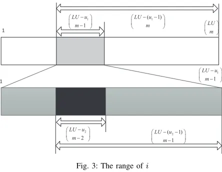
First, we determine the range ofiaccording tou1. The gray segment in the top half of Figure 3 illustrates the range ofi
when u1 is given. Define
(
LU m
)
−
(
LU −(u1−1)
m
)
as ∆1, then i ∈
[
∆1+ 1,∆1+
(
LU−u1
m−1
)]
, where
(
LU m
)
denotes the total number range of i and
(
LU −(u1−1)
m−1
)
denotes the number range ofiwhen the first user number is greater than or equals tou1.
1
LU m æ ö ç ÷ è ø
1 ( 1)
LU u m -
-æ ö
ç ÷
è ø
1
1
LU u m
-æ ö
ç ÷
-è ø
1
1
1
LU u m
-æ ö
ç ÷
-è ø
2 ( 1)
1
LU u m
-
-æ ö
ç - ÷
è ø
2
2
LU u m
-æ ö
ç - ÷
[image:4.612.325.547.297.469.2]è ø
Fig. 3: The range ofi
Second, we determine the range ofiaccording tou1andu2. The black segment in the bottom half of Figure 3 illustrates the range of i. Define
(
LU−u1
m−1
)
−
(
LU−(u2−1)
m−1
)
as
∆2, theni∈
[
∆1+ ∆2+ 1,∆1+ ∆2+
(
LU−u2
m−2
)]
,
where
(
LU−u2
m−2
)
denotes the number range ofiwhen the first and second user number are greater than or equal tou1
andu2 respectively.
Then, repeat the similar step until reaching the condition of um−1. Correspondingly, define
(
LU−uj−1
m−j+ 1
)
−
(
LU−(uj−1)
m−j+ 1
)
as ∆j , then
i∈
[
m∑−1
j=1
∆j+ 1,
m∑−1
j=1
∆j+
(
LU−um−1
1
)]
.
Finally, when given u1, u2, u3,· · · , um, we can eventually
obtain Eq. (4):
i=
m∑−1
j=1
Example 1. We assume thatL= 1, U = 20,m= 4and the receiving antennas at BS is Nr = 4. Let Bm be m-user
grouping matrix. Taking 4-user grouping as an example, we can writeB4 as follows:
group index 1 2 ... 4222 ... ΩNU4
B4=
1 1 · · · 0 · · · 0
1 1 · · · 0 · · · 0
1 1 · · · 0 · · · 0
1 0 · · · 0 · · · 0
0 1 · · · 0 · · · 0
· · · ·
0 0 · · · 1 · · · 0
· · · ·
0 0 · · · 1 · · · 0
· · · ·
0 0 · · · 1 · · · 0
· · · ·
0 0 · · · 1 · · · 0
· · · ·
0 0 · · · 0 · · · 1
user1 user2 user3 user4 user5 · · · user8 · · · user10 · · · user16 · · · user18 · · · user LU ,
where each element indicates whether the user is involved in the group or not. According to Eq. (4), if group
ΩNU
m,i= (8,10,16,18), we can get the index i of Ωm,iNU in
set ΩNUm equals 4222, which is demonstrated in the 4222-th column ofB4.
As the number of all user groups in set Ω is
|Ω|=
Nr
∑
m=1
ΩNUm = Nr ∑ m=1 ( LU m )
, based on Lemma 1, we can write the index of user group Ωg in setΩ as
g=
m∑−1
n=1 ( LU n ) + m∑−1
j=1
∆j+ (um−um−1), m >1
um , m= 1
, (5)
where set Ω={Ω1,· · ·, Ωg,· · · , Ω|Ω|
}
and user groupΩg=
(u1, u2,· · ·, um).
For example, the index of Ωg =ΩNUm,i = (8,10,16,18)in
setΩisg= m∑−1
n=1 ( LU n ) + m∑−1
j=1
∆j+ (um−um−1)=5572.
Then, the maximum capacity of virtual MIMO from user group Ωg tol-th receiving BS can be expressed as
Ψg,l= log2det
(
INr+
Es
ΥΩgσ
2Hg,lHg,l
H
)
. (6)
To achieve the maximum system capacity, the receiving BS selection and dynamic user grouping criterion can be written as
Group−Capacity (Υ,L) = arg max g,l
{Ψg,l}. (7)
The criterion (7) shows the ideal system throughput for grouped users, however, it does not give the user grouping rule with MIMO equalization and demodulation techniques. In this paper, we consider the MMSE equalization and AM with BER constraint for virtual MIMO systems. From Eq. (2), we get the receiving SNR of user uatl-th receiving BS after MIMO equalization as [9]
SN Ru,l =
Es
σ2[(H
g,lHHg,l+σ 2 EsI|ΥΩg|
)−1]
u,u
−1. (8)
Then, the capacity using post-processing SNR can be ex-pressed as
Ψg,lPost=
∑
u∈ΥΩg
log2(1 +SN Ru,l). (9)
The capacity in Eq. (9) is the upper bound for ideal transmissions after MMSE equalization. When we consider the practical techniques, such as AM techniques, the transmission rate is decided by the SNR and the BER through the use of modulation techniques. Specially, we consider a variable rate modulation using M-ary quadrature amplitude modulation (MQAM) in this work. In [33], the BER for an AWGN channel with MQAM and ideal coherent detection is bounded by
BERφ≤0.2e−12.φ5SN R−1 , (10)
where2φis the modulation order. Then, the maximum spectral efficiency of useruafter AM techniques is
φu,l=
⌊
log2
(
1− 1.5SN Ru,l
ln(5BERtarget)
)⌋
, (11)
whereBERtargetis the upper bound BER constraint for signal transmission. So the transmission efficiency of the virtual MIMO is
Rg,l=
∑
u∈ΥΩg
φu,l. (12)
Then, we get the user grouping criterion based on MMSE equalization and AM techniques as
Group−MMSE−AM(Υ,L) = arg max g,l
{Rg,l}. (13)
In addition, when user fairness needs to be taken into account, the transmission efficiency of each user should be weighted by a fairness factor. An effective approach to get the fairness factor is using proportional scheduling. For criterion (13), the weighted factor for spectral efficiency of useru, i.e.
φu,l, at n-th time slot can be calculated based on smoothing
window method as follows [34]:
wu,lFP(n) =
1 ¯
φu,l(n)
, (14)
where
¯
φu,l(n) =
(
1−T1 W
)
¯
φu′,l(n−1) + T1
Wφu′,l, u=u ′
(
1−T1 W
)
¯
φu,l(n−1) , others
andTW is smoothing window length.
B. Joint User Grouping and Resource Allocation in Multi-cell SC-FDMA Uplink
For multi-cell SC-FDMA uplink system, adjacent time-frequency RBs which can only belong to one receiving BS should be assigned to one user group. Assume that NRB
consecutive RBs are available to be allocated to users, we can determine the allocation pattern numberJ =NRB(NRB+1)
2 +1.
pattern 1 2 · · · · J−1 J
TNRB×J =
0 1 · · · 1 0 · · · 1 0 · · · 0 1
0 0 · · · 1 1 · · · 1 1 · · · 1 1
0 0 · · · 0 1 · · · 1 1 · · · 1 1
0 0 · · · 0 0 · · · 0 1 · · · 1 1
..
. ... ... ... ... · · · 0 ... · · · ... 1
0 0 · · · 0 0 · · · 0 0 · · · 1 1
0 0 · · · 0 0 · · · 0 0 · · · 1 1
RB1
RB2
RB3
RB4 · · ·
RBNRB−1
RBNRB
. (15)
Based on the idea of criteria for receiving BS selection, user grouping and RBs allocation, we first calculate the RB resource metric matrix for user groups atl-th receiving BS as follows:
group index 1 2 · · · |Ω|
Ml
NRB×|Ω=|
m1,1,l m1,2,l · · · m1,|Ω|,l
m2,1,l m2,2,l · · · m2,|Ω|,l
· · · · · · · · · · · ·
mNRB,1,lmNRB,2,l· · · mNRB,|Ω|,l
RB1
RB2
· · ·
RBNRB
, (16)
where the elements {mj,g,l} are calculated according to
E-q.(12), i.e. mj,g,l=Rj,g,l.
To achieve BS selection gain in one cluster, we derive the metric for all RBs, user groups and receiving BSs as follows:
MN
RB,|Ω|L=[M 1
NRB×|Ω|,· · ·,M l
NRB×|Ω|,· · ·,M L
NRB×|Ω|].
(17) From resource pattern (15), we express the transmission rate forg-th user group tol-th receiving BSs atj-th resource pattern as
ηj,g,l=sum
(
MlN
RB×|Ω|(:, g) .∗ T(:, j)
)
. (18)
Define|Ω|J L×1resource allocation vectorδand|Ω|J L×
1 rate vector of user groups η as
δ=[δ1,1,1,· · · , δJ,1,1,· · ·, δj,g,1,· · ·, δJ,|Ω|,1,· · · , δj,g,l, · · ·, δ1,1,L,· · · , δJ,1,L,· · ·, δj,g,L,· · · , δJ,|Ω|,L]T
and
η=[η1,1,1,· · · , ηJ,1,1,· · ·, ηj,g,1,· · ·, ηJ,|Ω|,1,· · · , ηj,g,l, · · ·, η1,1,L,· · ·, ηJ,1,L,· · · , ηj,g,L,· · ·, ηJ,|Ω|,L]T
whereδj,g,lis the assignment index indicatingg-th user group
occupyingj-th RB pattern inl-th cell andδj,g,l={0,1}, j= 1,· · ·, J; g= 1,· · · |Ω|; l= 1,· · ·L.
Then, we write the optimization problem of the joint re-source allocation as M JRA(Ω,T, L)
arg max δ
{
ηTδ} (19)
subject to
AC1 :A1δ≤1NRB×1 (19a) AC2 :A2δ≤1U×1 (19b)
AC3 :A3δ≤1L×1 (19c)
AC4 : BERφ≤BERtarget (19d)
AC5 :δj,g,l={0,1},
j= 1,· · · , J; g = 1,· · · |Ω|; l= 1,· · ·L (19e)
where A1 = 11×L ⊗ (T ⊗ 11×|Ω|), A2 = 11×L ⊗ (11×J ⊗ B), A3 = (11×J ⊗ 11×|Ω|) ⊗ IL , and B =
[
B1, B2, · · ·, Bm, · · ·, BNr ] is the user
group-ing matrix.
The aim of (19) is to maximize the total throughput. The constraint AC1 is to ensure that each RB can only be allocated to one user group, AC2 is to ensure that each user can occupy one resource pattern at most, AC3 is to ensure that each user group and RB can only belong to one receiving BS and AC4 is the BER constraint.
C. Solution Algorithm to the Joint Resource Allocation Prob-lem
The optimization problem (19) is a typical binary integer programming problem. So it can be converted to Office As-signment Problem (OAP) [35] and use a linear programming (LP)-based BNB algorithm [36] to solve the problem.
However, BNB algorithm is too complex for a practical implementation especially when the number of cells, users and RBs becomes large. In order to reduce the complexity, we decompose the problem (19) into a series of lower degree dimension sub-problems which can be modeled as bipartite graphs. Based on the consideration of constraints (19a) and (19b), we regroup the elements in setΩto create the complete user group setΩCUG={ΩCUG
i
}
so that each subset ΩCUG
i
contains the groups with all users but has no duplicate users. Similarly, we create the complete RB pattern set TCRP =
{
TCRP
j
}
so that each subset TCRP
j contains the RB pattern
with all RBs but has no duplicate RBs.
1) Construction of the Complete RB Pattern SetTCRP:
Lemma2. If there areNRB RBs available to be allocated,
the size of the RB pattern setTCRP will be2NRB−1.
Proof:Considering aNRB-RB sequence with the order of
RB1, RB2,· · · , RBNRB, we insert a underline between each
of RBs to construct a new sequence
ω={RB1, , RB2, ,· · · , , RBNRB}.
Only 0 and 1 can be put on these underlines. Putting 0 on the underline betweenRBi and RBi+1 means that RBi and
RBi+1 are assigned to the same RB pattern and vice versa.
Through changing the values put on these underlines, we can obtain all pattern subsetTCRPj and derive the size of the RB pattern set TCRP= 2NRB−1 by multiplication principle.
• Generating The Indexes of Elements inTCRP:
Definej to be the index of subsetTCRPj inTCRP, then, j
equals the value of the binary sequence inserted into sequence
ω corresponding to TCRP
Example2. Assume there areNRB = 6RBs in the system,
which are RB1, RB2,· · · , RB6. Given the inserted binary
sequence(1,1,0,0,1), the sequenceω is shown as follows:
ω={RB1, 1, RB2, 1, RB3, 0, RB4, 0, RB5, 1, RB6}.
It means that all RBs are divided into 4 RB pat-terns to form a complete RB pattern subset TCRP
25 =
{(RB1),(RB2),(RB3, RB4, RB5),(RB6)} whose index is
25 inTCRP.
2) Construction of the Complete User Group Set ΩCUG:
With the integer partition of LU users, we can know the
LU users can be divided into how many groups and each group contains how many users. Then, by the operation of user permutations and combinations based on the partition result, we can obtain all the complete user subsets.
• Generation Process of Complete User Group SetΩCUG:
We assume that the total user number in one cluster isLU
and the receiving antennas number at each BS is Nr.
Step1. Generating the integer partition ofLU
Call theProcedure #1shown in APPENDIX A to complete the integer partition operation of LU and obtain the partition matrixQwhose sum of each row vector equalsLU. Here, the integer partition operation of LU means listing all possible values ofn1, n2,· · ·, nLU, which meet the requirement of the
following equation:
n1+n2+· · ·+ni+· · ·+nLU =LU, (20)
where0≤ni≤ni+1≤Nr(1≤i≤LU−1).
Step2. Generating the user group set ΩCUG based on the
integer partition of LU
Let ˆqi be the i-th row vector of Q. Then, obtain setqi=
{qi,1, qi,2,· · · , qi,W}by deleting the 0 elements in ˆqi, where
0 < qi,1 ≤qi,2≤ · · · ≤qi,W ≤LU,W ≤LU. Perform the
similar operations until each row vector of Qis traversed. Selectqi,1 users fromLU users, and call theProcedure #2
shown in APPENDIX A to create user groupΩNU
qi,1, and then selectqi,2users from the rest ofLU−qi,1users to create user
group ΩNU
qi,2, repeat the similar operations until user group ΩNU
qi,W is obtained.
Let ΩCUGqi = {Ω NU
qi,1,Ω
NU
qi,2,· · ·,Ω
NU
qi,W}. Then put all
complete user group subsets into set ΩCUG in the order of i, and finally obtain the complete user group setΩCUG.
In addition, according to the analyses above, we can derive the size of ΩCUG
qi as follows:
Ξi=
(
LU
qi,W
) (
LU −qi,W
qi,W−1
)
· · ·
LU −
W
∑
w=2
qi,w
qi,1
ξ1!ξ2!· · ·ξr!· · ·ξNr!
,
(21) where ξr, 1 ≤ r ≤ Nr is the number of elements in qi = {qi,1, qi,2,· · ·, qi,W}, which is equal tor.
Example 3. Let Nr = 4, LU = 5, and the user set is {u1, u2, u3, u4, u5}.
Step1:
FromProcedure #1, we can derive that the partition number ofLU is 6 and all the partitions are(1,1,1,1,1),(1,1,1,2,0),
(1,1,3,0,0), (1,2,2,0,0), (1,4,0,0,0), (2,3,0,0,0). Then, the partition matrix Qcan be expressed as follows:
Q=
1 1 1 1 1 1 1 1 2 0 1 1 3 0 0 1 2 2 0 0 1 4 0 0 0 2 3 0 0 0
, (22)
whereq2= (1,1,1,2) means that 5 users are divided into 4
groups and each group contains 1 user, 1 user, 1 user and 2 users respectively.
Step2:
Takeq2 = (1,1,1,2) as an example, we can get the size
of ΩCUG
q2 as
Ξ2=
(
5 1
)(
5−1 1
)(
5−1−1 1
)(
5−1−1−1 2
)
3!1! =10.
(23) The complete user group subsets in ΩCUG
q2 corresponding toq2 is
ΩNU
q2,1 Ω
NU
q2,2 Ω
NU
q2,3 Ω
NU q2,4
ΩCUG
q2 =
{(u1) (u2) (u3) (u4, u5)}
{(u1) (u2) (u4) (u3, u5)}
{(u1) (u2) (u5) (u3, u4)}
{(u1) (u3) (u4) (u2, u5)}
{(u1) (u3) (u5) (u2, u4)}
{(u1) (u4) (u5) (u2, u3)}
{(u2) (u3) (u4) (u1, u5)}
{(u2) (u3) (u5) (u1, u4)}
{(u2) (u4) (u5) (u1, u3)}
{(u3) (u4) (u5) (u1, u2)}
. (24)
Add elements of ΩCUG
q2 into the complete user group set ΩCUG.
• Size Analysis of Complete User Group SetΩCUG:
The size of complete user group setΩCUGmainly depends on the partitions of LU users. In the following, we first investigate the partition number ofLU users with the group user number limitNr, then, discuss the size of complete user
group setΩCUG.
Lemma3. LetP≤Nr(LU)be the partition number ofLU
with no parts greater thanNr, we have the following theorem:
P≤Nr(LU) =
LU
∑
m=0
P≤Nr−1(m)×b
LU−m, P≤Nr−1(0) = 1,
(25) wherebm=
{
1, m=i∗LU , i= 0,1,· · ·
0,others is the coefficient
of tm in the Taylor’s expansion of 1
(1−tLU).
Proof: Let A(LU, Nr − 1) be the number of
posi-tive solutions of Diophantine equation
N∑r−1 i=1
p(≤Nr−1)(t) = 1
(1−t)(1−t2)···(1−tNr−1) be the generating func-tion. Here A(LU, Nr −1) is the coefficient of tLU in the
p(≤Nr−1)(t).
Generating function p(≤Nr−1)(t)can be expressed as
p(≤Nr−1)(t) = 1
(1−t)(1−t2)···(1−tNr−1)
= ∑∞ i=0
A(i, Nr−1)ti
. (26)
The Taylor’s expansion of 1
(1−tLU) is
1
(1−tLU) =
∞
∑
j=0 bjtj,
so the generating function p(≤Nr)(t)can be expressed as:
p(≤Nr)(t) = 1
(1−t)(1−t2)···(1−tNr−1)×
1
(1−tNr)
= ∑∞ i=0
A(i, Nr−1)ti×
∞
∑
j=0 bjtj
= ∑∞ s=0
[∑s
m=0
A(m, Nr−1)×bs−m
]
ts
. (27)
We select the coefficient oftLU, then the following
conclu-sion can be obtained:
A(LU, Nr) =
LU
∑
m=0
A(m, Nr−1)×bLU−m. (28)
Due toP≤(Nr)(LU) =A(LU, N
r), we can know that:
P≤(Nr)(LU) =A(LU, N
r)
= LU∑ m=0
A(m, Nr−1)×bLU−m
= LU∑ m=0
P≤(Nr−1)(m)×b
LU−m
. (29)
It cannot obtain the size of complete user group setΩCUG
fromP≤(Nr)(LU)directly. However, we can calculate the size
ΩCUG using Eq. (21) after the partition procedure of user LU.
Lemma4. The size of complete user group setΩCUGis
ΩCUG=∑
i Ξi
=∑ i
LU
qi,W
LU−qi,W
qi,W−1
···
LU−
W
∑
w=2 qi,w
qi,1
ξ1!ξ2!···ξr!···ξNr!
,
(30) where0< qi,1≤qi,2≤ · · · ≤qi,W ≤LU,W ≤LU.
Proof: The proof can be easily extended from combina-tion and multiplicacombina-tion principles by considering all particombina-tion results. We omit the details due to page limit.
3) Algorithm for the Solution of Joint Resource Allocation Problem: After the generation of complete RB pattern set and complete user group set, iterative Hungarian algorithm can be used to obtain the resource allocation. However, according to
Lemma4, the size of complete user group setΩCUGgrows
rapidly with the increase of user and RB numbers so that the computational complexity is still unbearable. Actually, when given a complete RB pattern subset, only one complete user group subset which belongs to a user partition can be selected as the best match. So, we can compress the complete user group set according to the user partition results before joint
resource allocation using greedy strategy. Inspired by these ideas, we present an efficient sub-optimal IHA URP algorithm to solve problem (19) with the following two phases:
i. Initial phase: integer partitions of users and RBs From section III. C. 1) and 2), we can obtain integer partitions of LU and NRB. Since RBs must be adjacent in
one pattern, complete RB pattern set TCRP can be obtained
as well.
ii. Running phase: complete user group set compression and joint resource allocation
First, compress the size of ΩCUG according to the user
partition results by greedy algorithm. When given a complete RB pattern subsetTCRP
j , we can getP≤Nr(LU)best matched
complete user group subsets based on partition results. Then, perform joint resource allocation. Select the complete user group subset and complete RB group subset with maximal sum-rate from the results of previous process.
The detailed workflow is described in the following.
• Generation of the Best Matched Complete User Group Subset from a User Partition:
Given a partitionqi={qi,1,· · ·, qi,W}and a complete RB
pattern subsetTCRPj ={TCRPj,1 ,· · · ,TCRPj,V }, we can generate the best matched complete user group subset using Hungarian algorithm with greedy strategy.
Step1:
Based on Lemma 1, the performance measure matrix of
TCRPj andΩNUqi for celll can be constructed as follows:
partition
group ΩNU
qi,1 · · · Ω
NU
qi,w · · · Ω
NU
qi,W
b
ηV×W,l=
b
η1,1,l
· · · · · ·· · · b
η1,w,l
· · · · · ·· · ·
b
ηv,1,l · · · ηbv,w,l · · ·
· · · · · · · · · · · ·
b
ηV,1,l · · · bηV,w,l · · ·
b
η1,W,l · · ·
b
ηv,W,l · · ·
b
ηV,W,l
TCRP
j,1 · · ·
TCRPj,v
· · ·
TCRP
j,V
,
(31) wherebηv,w,l= max
g∈ΩNU
qi,w
{ηv,g,l}, the corresponding group index
ˆ
g= arg max g∈ΩNU
qi,w
{ηv,g,l} and1≤l≤L.
Then, the performance measure matrix ofTCRPj andΩNUqi
for all cells in one cluster is
b
η= [ηbV×W,1,· · ·,ηbV×W,l,· · ·,ηbV×W,L]. (32)
Step2:
Find the best match between resource pattern and user group by the operation (v∗, w∗, l∗, g∗) = arg max
v,w,l,gˆ {b
ηv,w,l|v∈[1, V], w∈[1, W], l∈[1, L]}, where
v∗, w∗, l∗ and g∗ mean the resource pattern index, part of partition qi, the index of cell and the group index,
respectively. Then the assignment index δvj,i∗,g∗,l∗ = 1, the
pre-allocated users are ΥΩg∗.
Step3:
Delete v∗-th row and w∗-th column from the matrix (31) whenl values from 1 toLand put each of it into matrix (32) respectively, then remove usersΥΩg∗ fromΥand update the
group set{ΩNUm
}
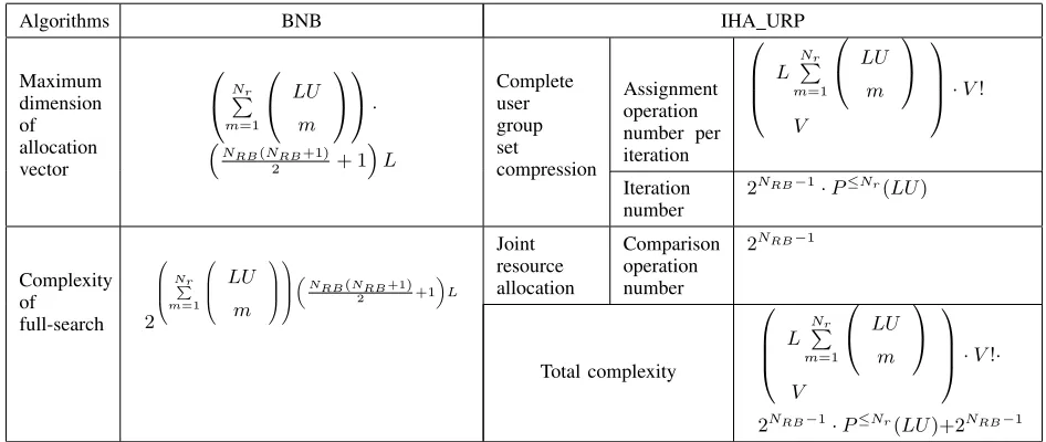
TABLE I: COMPLEXITY COMPARISON
Algorithms BNB IHA URP
Maximum dimension of allocation vector
N∑r
m=1
LU
m
· (
NRB(NRB+1)
2 + 1
)
L
Complete user group set
compression
Assignment operation number per iteration
L
Nr
∑
m=1
LU
m
V
·V!
Iteration number
2NRB−1·P≤Nr(LU)
Complexity of
full-search 2
Nr∑
m=1
LU
m
(
NRB(NRB+1)
2 +1
) L
Joint resource allocation
Comparison operation number
2NRB−1
Total complexity
L
Nr
∑
m=1
LU
m
V
·V!·
2NRB−1·P≤Nr(LU)+2NRB−1
Step4:
Then, the sum-rate of TCRPj and ΩNUqi in cell l equals
Rj,i =
∑
v
∑
g
∑
l
b
ηv,w,l·δv,g,lj,i and the assignment index
cor-responding to them isδj,i.
• Iterative Process to Obtain the Resource Allocation: After2NRB−1·P≤Nr(LU)iterations, we get all best
match-es between {TCRPj } and {ΩCUGqi
}
for each cell, the sort operation is used to find the resource allocation result:
(j∗, i∗) = arg max j,i
{
Rj,i|j∈
[
1,TCRP], i∈[1, n]}.
Then, the maximal sum-rate is R∗ = Rj∗,i∗ and the
corresponding resource assignment index δ∗ = δj∗,i∗ is the solution of joint resource allocation problem (19).
4) Complexity Analysis: The computational complexity of the proposed IHA URP algorithm comes from two aspects, one is to carry out the complete integer partition operation of
LU andNRB, which are done only once. The other is to get
the optimum resource allocation result based on the partition results ofLU and complete RB pattern set.
• Complexity Analysis of integer partitions ofLU andNRB
for IHA URP in initial phase:
TheProcedure #1in APPENDIX A is designed to perform the integer partition operation of LU and obtain the integer partition matrix Q, where the recursive operations are used. So the upper bound of the complexity is given as
T(LU) = 1 + LU∑−1
j=1
T(j), (33)
where T(LU) denotes the number of recursive calls when there areLU users. By assuming thatT(LU) = 1whenLU = 1 and solving the above equation, we can get
T(LU) = 2LU.
Similarly, the complexity of integer partition of NRB can
be expressed asT(NRB) = 2NRB.
• Complexity Analysis of joint resource allocation for I-HA URP in running phase:
According to the analysis above, the operations in initial phase are performed only once, so the running time of the proposed algorithm mainly comes from running phase. In order to evaluate the proposed algorithm, we take the BNB algorithm as a comparison.
Since the accurate complexity analysis of the algorithms solving the joint resource allocation problem is difficult, we use the maximum dimension of allocation vector and the full search number in the optimization to simply analyze the algorithm complexity for BNB algorithm. For proposed IHA URP algorithm, iterative processes are performed with compression operations where the assignment operations are performed by Hungarian algorithm with greedy strategy. As a combination optimization problem, the complexities of the processes are demonstrated by combination numbers and the iteration number which is given byLemma2andLemma3. A comparison of computational complexity between BNB and IHA URP algorithm is represented in Table I, where
V = min
{
NRB, L
Nr
∑
m=1
(
LU m
)}
.
Consider the case that L = 2, NRB = 6, U = 6 and
Nr= 2. For BNB, the maximum dimension of allocation
vec-tor is 3432 and the complexity of full-search is1.364×101033. For the proposed IHA URP algorithm, the total complexity is
(
156 6
)
·6!·32·7+32≈2.929×10¹⁵.
From the analysis above, we can find that the proposed IHA URP algorithm dramatically reduce the complexity. Moreover, since the sub-problems are independent, the solu-tion operasolu-tions for theseP≤Nr(LU)×2NRB−1sub-problems
can be run in parallel mode for fast processing in practice.
IV. SIMULATION EXPERIMENTS A. Simulation Settings
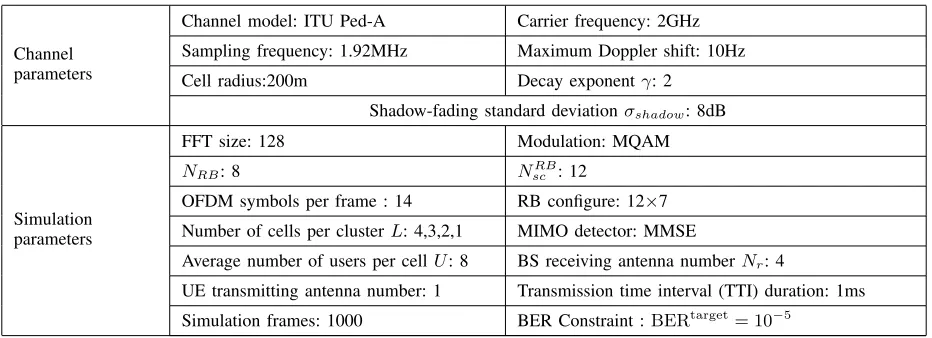
TABLE II: SIMULATION PARAMETERS
Channel parameters
Channel model: ITU Ped-A Carrier frequency: 2GHz
Sampling frequency: 1.92MHz Maximum Doppler shift: 10Hz
Cell radius:200m Decay exponentγ: 2
Shadow-fading standard deviationσshadow: 8dB
Simulation parameters
FFT size: 128 Modulation: MQAM
NRB: 8 NscRB: 12
OFDM symbols per frame : 14 RB configure: 12×7
Number of cells per clusterL: 4,3,2,1 MIMO detector: MMSE
Average number of users per cellU: 8 BS receiving antenna numberNr: 4
UE transmitting antenna number: 1 Transmission time interval (TTI) duration: 1ms
Simulation frames: 1000 BER Constraint :BERtarget= 10−5
the simulations based on LTE uplink wherein the BS is equipped with four receiving antennas and each user has only one antenna. The simulation parameters are listed in Table II. In addition, we adopt the pedestrian test environment channel A as suggested by ITU-R M.1225 [37]. In the simulations, we use the scenario with perfect power control in one cell, that is, the transmitting power changed adaptively in order to guarantee that the users within a cell will compensate the overall slow fading including path loss and shadowing then obtain the same average channel quality. Then the normalized coefficient of large scale fading is modeled as
βm,l,u,j =
z
(
dl,u,j/¯ dl
)γ,
wheredl,u,j is the distance between theu-th user of thej-th cell to the BS in the l-th cell, d¯l is the reference average
distance so that the mean of βm,l,u,l is 1, γ is the decay
exponent and z is a log-normal random variable, i.e., the quantity 10log10z is distributed zero-mean Gaussian with standard deviation of σshadow. In addition, we define the
transmitting SNR as Es/
σ2 in these simulations.
The common simulation parameters are illustrated in Table II.
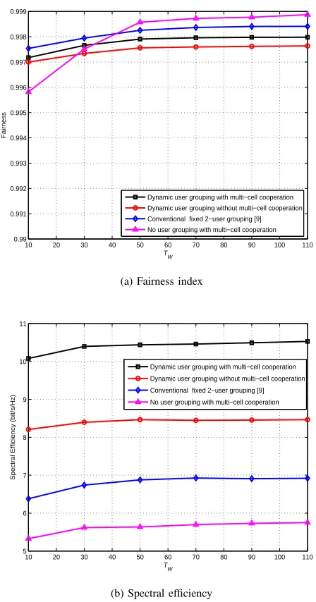
B. Simulation Results
For comparison purpose, six different joint resource alloca-tion algorithms with user grouping are implemented in the following simulations. The first one is the algorithm with dynamic user grouping proposed in this paper where users in all coordinated cells can be grouped, denoted as ‘Dynamic user grouping with multi-cell cooperation’. The second one is the algorithm with dynamic user grouping but without cell cooperation where only users in the same cell can be grouped, denoted as ‘Dynamic user grouping without multi-cell cooperation’. The third one is the algorithm with fixed 2-user grouping which has 32 users in a conventional large cell, i.e. the same number of users compared to multi-cell system with L=4, where the large scale fadingβ = 1for all users, denoted as ‘Conventional fixed 2-user grouping [9]’. The fourth one is the problem with fixed 2-user grouping
in conventional large cell solved by Hungarian algorithm in [18], denoted as algorithm ‘Conventional fixed 2-user grouping [18]’. The fifth one is the algorithm with fixed 1-user grouping and multi-cell cooperation, denoted as ‘No user grouping with multi-cell cooperation’. The last one is the algorithm with fixed 1-user grouping but without multi-cell cooperation, denoted as ‘No user grouping without multi-cell cooperation’, which is the baseline algorithm serving to show how much improvement can be achieved by our proposed algorithm. In addition, to evaluate the above algorithms in actual systems, grouping criterion (13) is used in above algorithms.
1) The Complexity and Performance of the Proposed I-HA URP Algorithm: For comparison purpose, IHA URP and BNB algorithms are used to solve the optimization problem (19). In the simulation, MATLAB R2013a is used to run the programs of the proposed IHA URP algorithm and traditional BNB algorithm for 150 simulation frames with transmitting SNR =15dB.
The comparison for running time between IHA URP and BNB algorithms is shown in TABLE III. From TABLE III, we can see that with the increase of cell and user numbers, the difference of time complexity between IHA URP and BNB is getting more and more obvious. When the cluster consists of 1 cell, the run time of those algorithms are close. However, when the cluster consists of 4 cells with 4 users per cell, the running time of BNB is more than 77 times of IHA URP. In addition, IHA URP is suitable for fast processing. As mentioned in Section III. C. 4), IHA URP can be run in parallel mode. Take the case of 4 cells with 6 users per cell in the simulation, the running time of IHA URP in parallel mode can be reduced to2486/(150×351×128)≈0.00037s per frame, which is less than one TTI.
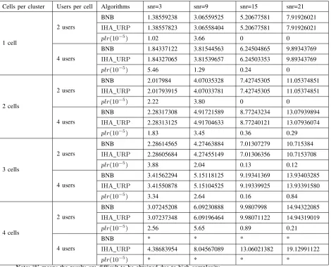
To evaluate the performance loss of IHA URP, we conduct the simulation for 1000 simulation frames. The simulation parameters and results are shown in TABLE IV, whereplr=
SEBN B−SEIHA U RP
SEBN B is the performance loss rate of IHA URP, SEBN B and SEIHA U RP denote the spectrum efficiency
TABLE III: RUNNING TIME (second) COMPARISON OF BNB ANDIHA URP(SNR=15dB)
Users
per
cell
1 cell 2 cells 3 cells 4 cells
IHA
URP BNB ratio
IHA
URP BNB ratio
IHA
URP BNB ratio
IHA
URP BNB ratio
2 users 9.08 10.88 1.20 20.72 28.66 1.38 47.62 84.88 1.78 271.64 437.94 1.61
4 users 11.15 15.17 1.36 57.52 109.79 1.91 198.46 1370.99 6.91 683.8622 52719.49 77.09
6 users 14.57 27.03 1.86 109.91 559.13 5.09 598.14 25088.32 41.94 2480.39 * *
Note: ‘*’ means the results are difficult to be obtained due to high complexity.
TABLE IV: SPECTRUM EFFICIENCY PERFORMANCESOF BNB ANDIHA URP(bit/s/Hz)
Cells per cluster Users per cell Algorithms snr=3 snr=9 snr=15 snr=21
1 cell
2 users
BNB 1.38559238 3.06559525 5.20677581 7.91926021
IHA URP 1.38557823 3.06558404 5.20677581 7.91926021
plr(10−5) 1.02 3.66 0 0
4 users
BNB 1.84337122 3.81544563 6.24504865 9.89343769
IHA URP 1.84327065 3.81539657 6.24503353 9.89343769
plr(10−5)
5.46 1.29 0.24 0
2 cells
2 users
BNB 2.017984 4.07035328 7.42745305 11.05374851
IHA URP 2.01793915 4.07033781 7.42745305 11.05374851
plr(10−5) 2.22 3.80 0 0
4 users
BNB 2.28317308 4.91721589 8.77243234 13.07939894
IHA URP 2.28313125 4.91704633 8.77240121 13.07936074
plr(10−5) 1.83 3.45 0.36 0.29
3 cells
2 users
BNB 2.28614565 4.27463884 7.01307279 10.715384
IHA URP 2.28605684 4.27455149 7.01306356 10.7153708
plr(10−5)
3.88 2.04 0.13 0.12
4 users
BNB 3.41562294 5.15118125 9.19341369 13.93403285
IHA URP 3.41550878 5.15104525 9.19339925 13.93391580
plr(10−5) 3.34 2.64 0.16 0.84
4 cells
2 users
BNB 3.07245208 6.09230888 9.9807998 14.94322085
IHA URP 3.07237348 6.09196464 9.98071122 14.94319019
plr(10−5)
2.56 5.65 0.89 0.21
4 users
BNB * * * *
IHA URP 4.38683954 8.04567089 13.06021382 19.12991122
plr(10−5) * * * *
Note: ‘*’ means the results are difficult to be obtained due to high complexity.
the close-to-optimal performance with much lower complexity than BNB. Since BNB algorithm is difficult to implement, IHA URP algorithm is used to demonstrate the performance of the joint resource allocation in the following simulations.
2) The Impact of User Grouping for Multi-cell Systems: To compare the proposed algorithm with fixed user grouping algo-rithms and other conventional joint user pairing and resource allocation algorithms, we simulate fixed 1-, 2-, 3-user grouping algorithms and the modified algorithms proposed in [9] and [18] by using AM techniques respectively, that is, replace the Shannon capacity with AM rate of Eq. (11). Figure 4(a) and (b) show the spectrum efficiency versus transmitting SNR for
[image:11.612.74.544.191.571.2]0 3 6 9 12 15 18 21 24 0
5 10 15 20 25 30
Transmitting SNR(dB)
Spectral Efficiency (bit/s/Hz)
Dynamic user grouping with multi−cell cooperation Dynamic user grouping without multi−cell cooperation Conventional fixed 2−user grouping [9] Conventional fixed 2−user grouping [18] No user grouping without multi−cell cooperation
(a) Different resource allocation algorithms
0 3 6 9 12 15 18 21 24
0 5 10 15 20 25 30
Transmit SNR(dB)
Spectral Efficiency (bit/s/Hz)
Dynamic user grouping with multi−cell cooperation Fixed 3−user grouping with multi−cell cooperation Fixed 2−user grouping with multi−cell cooperation No user grouping with multi−cell cooperation
(b) Fixed user grouping algorithms
0 3 6 9 12 15 18 21 24
0 5 10 15 20 25 30
Transmitting SNR (dB)
Spectral Efficiency (bit/s/Hz)
BER Constraint : BERtarget=1e−3
BER Constraint : BERtarget=1e−4
BER Constraint : BERtarget=1e−5
[image:12.612.68.285.68.246.2](c) Different BER constraints
Fig. 4: Spectral efficiency versus transmitting SNR for different resource allocation algorithms and different BER constraints
From Figure 4(a), we can see that ‘Dynamic user grouping with multi-cell cooperation’ algorithm outperforms ‘Dynamic user grouping without multi-cell cooperation’ algorithm and ‘No user grouping without multi-cell cooperation’ algorithm, which due to the former can achieve multi-cell selective gain and grouping multiplexing gain while the latter two algorithms cannot. The ‘Dynamic user grouping with multi-cell cooperation’ algorithm achieves much higher spectral efficiency than the ‘Conventional fixed 2-user grouping [9]’ algorithm and ‘Conventional fixed 2-user grouping [18]’ al-gorithm. The main reason is that the latter two algorithms can only have fixed 2-user grouping regardless of the value of SNR while the former has 2-user grouping in low SNR region and hasNr -user grouping in high SNR region which
achieves grouping multiplexing gain and multi-cell selective gain. In addition, any number of consecutive RBs are assigned to one user group in ‘Dynamic user grouping with multi-cell cooperation’ algorithm and ‘Conventional fixed 2-user grouping [9]’ algorithm while one RB is assigned to one user group in ‘Conventional fixed 2-user grouping [18]’ algorithm, so the former two algorithms obtain better RB selective gain than the latter.
From Figure 4(b), we can see that the spectral efficiency of ‘Dynamic user grouping with multi-cell cooperation’ algo-rithm always outperforms that of fixed 1-, 2-, 3-user grouping algorithms in both high SNR region and low SNR region. The performance gain comes from grouping multiplexing gain and multiuser selection gain. In the low SNR region, due to the BER constraint, the algorithms of small fixed grouping user number work well while the algorithms of large fixed grouping user number work well in high SNR region.
From Figure 4(c), we can see that the spectral efficiency rises when BER performance constraint drops, which mainly because the number of active grouping users becomes large. This leads to different spectral efficiency due to the different grouping user multiplexing gain and multiuser selection gain. So, the proposed ‘Dynamic user grouping with multi-cell cooperation’ algorithm can achieve trade-off between BER performance and spectral efficiency as required.
3) The Impact of Cell Number in One Cluster: In this simulation, we set L=1,2,3 and 4 respectively and use the ‘Dynamic user grouping with multi-cell cooperation’ algorith-m and ‘Fixed 2-user grouping with algorith-multi-cell cooperation’ algorithm to evaluate the impact of cell number in one cluster. To ensure the fairness, we let each cell contains Nˆ = NRB
L
RBs so that one cluster has the same number of RBs in different experiments. In Figure 5, we show the spectrum efficiency versus transmitting SNR for one cluster consisting of different number of cells.