A Pattern System for Network Management Interfaces
Rudolf K. Keller Jean Tessier Gregor v. Bochmann
Network management systems are used to control and monitor the components of distributed
systems such as communication networks, where many different subsystems need to collaborate
together to offer a service. Communication networks are large dynamic systems, comprising parts
from various vendors and evolving over time, with parts getting grafted on and others being
removed. Network management is a challenging task in that it usually requires remote access to
widely distributed information coming from various sources. Operations have to be performed on
large numbers of system components. Moreover, the access interface to the components can
greatly vary, depending on their nature, type, and manufacturer. We define a network management
interface (NMI) as the middle layer of a network management system, situated between the
high-level control processes and the low-high-level components of the system [12]. The lower layers, which
usually depend heavily on the execution platform at hand, are thus not part of the NMI.
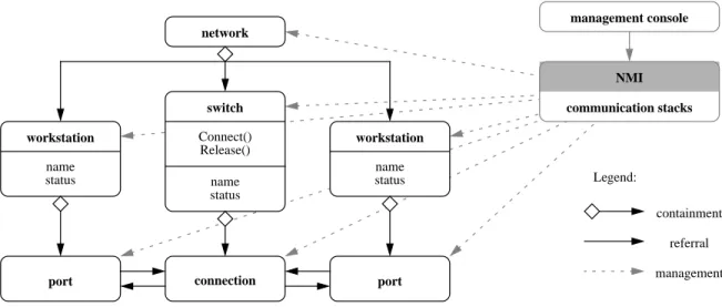
Figure 1 illustrates a sample distributed system (network) under management. The system
consists of two workstations communicating through a switch. Each workstation has a
communication port that is attached to each end of the connection path, and the path itself is
contained in the switch. The management system includes a management console that has access
and control over all the components of the network through a symbolic representation provided by
the NMI. Note that the NMI must include a number of communication stacks to access all the
various components.
International standardization bodies have produced various tools for defining network
Management Information Service (CMIS) of Open Systems Interconnection (OSI) [12], and the Simple Network Management Protocol (SNMP) of the Internet [9]. Whereas CMIS, along with CMIP, its protocol for information exchange between systems, is based on the object-oriented
paradigm, SNMP uses tables not unlike the tables used in the relational model of databases.
However, SNMP is moving towards the object-oriented paradigm, with its new version SNMPv2
embodying some notion of inheritance.
In the IGLOO project, we have developed Layla1, a prototype pattern-based framework for
NMIs. In designing Layla, we wanted to leverage off commercial implementations of standardized
network management protocols, and therefore came up with a number of wrapper classes that
encapsulate the specific details of any particular protocol engine. Layla supports OSI NMIs and
therefore includes provisions for the object-oriented nature of CMIS which are not necessarily
found in other protocols for network management. Using Layla, we have built several NMIs to
date, in cooperation with Teleglobe Canada Inc., our main industrial partner.
1 In the Zohar, Layla is an angel in charge of the newly created spirits (Gustav Davidson, A Dictionary of Angels, Free Press, 1967).
Figure 1: Sample network managed by network management system.
port name status network workstation name status switch Connect() Release() workstation name status port connection management console communication stacks NMI Legend: containment referral management
At an early stage in the development of Layla, we decided to take an approach based on
design patterns. Aware of their potential of making architectures easier to modify, maintain, and
reuse and of their documentation value [2, 3, 7, 11], we wanted to verify whether these qualities
also hold in a domain as complex as NMIs, and in which way domain-specific aspects would come
into play. A further objective was to organize the system of patterns that would result from our
design in a systematic and coherent way. The resulting framework architecture can be described as
a heterogeneous system of design patterns. The system consists of previously published,
general-purpose patterns, several new and domain-specific patterns taken from NMI standards, as well as
a couple of basic patterns relevant in Layla’s application programming interface (API). The
patterns are implemented as a system of C++ classes that form the framework. The framework
encapsulates to a large extent the underlying communication API (henceforth simply referred to as
“API”), as has been shown with the adoption of two different, commercially available APIs.
Below, we first discuss currently available APIs for NMIs and the need for application
frameworks. Then, we describe the pattern system underlying the Layla framework and discuss
three of its key patterns, the Manager-Agent, Managed Object, and Remote Operation patterns.
The Manager-Agent pattern captures the regrouping of resources under the supervision and control
of a responsible entity. The Managed Object pattern provides a one-to-one mapping to the
individual resources in a managed system, as well as an interface hiding the specifics of the actual
resources. The third key pattern, the Remote Operation pattern, encompasses clients that need to
invoke operations on remote objects as if they were local. Finally, we put Layla into perspective
and draw some conclusions.
APPLICATION PROGRAMMING INTERFACES FOR NETWORK
MANAGEMENT INTERFACES
are often called Application Programming Interfaces (APIs). An API typically includes data
structures and function prototypes, as well as a set of precompiled libraries that implement those
functions. A developer can describe a network management function in terms of API calls and
implement the NMI by reusing the code in the libraries (see Box 1 APIs for network management
interfaces).
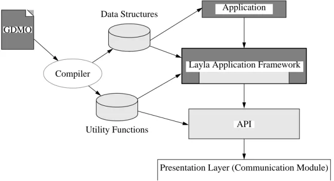
Developing an NMI based on an API usually involves a number of steps (see Figure 2).
First, the developer must specify the NMI using the specification language(s) supported by the
API. For example, CMIS uses one language for describing object classes and relationships
(GDMO) and another for the data structures used by the objects (ASN.1). In contrast, the SNMP
standard uses only one specification language to describe data structures (ASN.1), and the
semantics are described using plain English. Once the specification has been written, an automated
tool is used to map it to a specific programming language, often C. The tool, typically some sort of
compiler, needs to generate the appropriate data structures and utility functions in the target Figure 2: Layered structure of NMI, with Layla mediating between object-oriented (dark
grey) and procedural (light grey) components.
Layla Application Framework
Presentation Layer (Communication Module) GDMO Data Structures Utility Functions Compiler API Application
implementation language. Once generated, the developer can use these structures and functions to
implement the NMI. The data structures are used by the application to pass information to the API.
The utility functions are used by the application to manage those structures, and by the API to
transfer data across process boundaries (via the presentation layer (communication module)). The
API also comprises management protocols for data exchange across the various computing
platforms typically found in today’s large and heterogenous networks.
Network management APIs are a powerful development tool, since they take care of many
low-level communication issues such as connection establishment/release, buffering,
synchronization, and type conversion between different computing platforms. Still, they exhibit
several shortcomings. First, most APIs available today provide only an interface to the C language,
whereas many NMI specification languages are object-oriented, imposing on the developer a
discrepancy of paradigms. Second, applications are highly dependent on the output of the
specification compiler, and any changes either to the initial specification or to the compilation
mechanism may require major modifications to the application code, ultimately leading to serious
maintenance problems. Furthermore, many APIs offer on the one hand functionality which is not
necessarily relevant to the NMI under development, yet are often limited to the lowest common
denominator of the functionalities provided by the various flavors of NMIs.
We felt that these shortcomings would best be addressed by devising an application
framework to mediate between the application and the API. The developer then simply has to deal
with the oriented specification of the NMI and the framework, which itself is
object-oriented, yet comprises a procedural kernel for interfacing with the API (Figure 2). Also, a
framework encapsulating the underlying API makes NMIs independent of the API that is actually
used. Furthermore, generated code can be hidden within the framework, and the framework can be
high-level services. Note that introducing such an additional framework layer may lead to
performance degradation. Our experience in the project, however, suggests that with careful
framework design, performance loss can be kept to a minimum.
For our framework development, Teleglobe supplied us with two different APIs, both geared
towards OSI NMIs as defined by the CMIS standards [12], and providing the low-level
functionality required. One of them, used at the beginning of our project, is BaseWorX from AT&T
[1], the other one, on top of which the current version 1.1 of Layla is built, is DM from Hewlett
Packard [4]. We have strived for complete encapsulation of the API into the framework, so that
the classes defined for a given NMI can be compiled with one API or the other, thus making the
NMI independent of the API that is actually used. However, since the NMI is dependent on the
structures generated by the specification compiler that comes with the API (see Figure 2), this
encapsulation can never be complete.
THE PATTERN SYSTEM OF LAYLA
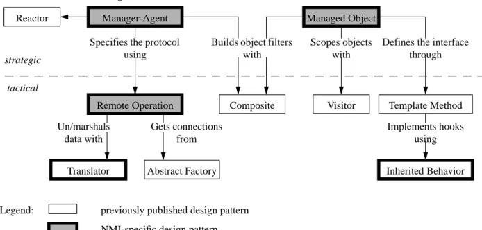
Figure 3 depicts the pattern system that constitutes the architecture of the Layla framework.
Strategic patterns [11] are placed at the top, and the more generic but less critical tactical patterns
are shown in the region below the separator line.2 Arrows stand for use-relationships, indicating
that the originating pattern uses the destination pattern for the functionality mentioned on the label
of the arrow. (Further information addressing pattern documentation and, specifically, the
documentation of Layla, can be found in Box 2 Documenting patterns and pattern systems.)
Each major task in Layla is described by a design pattern, many of which come from the
literature [3, 10]. This indicates that the published design patterns are indeed expressive and
generic enough to be easily applied to a new application domain. Several tasks and design solutions
2 Note that the distinction between strategic and tactical pattern refers to the role of a pattern in a particular
that were not already design patterns originated from the constraints imposed by the underlying
network management standards. Since these solutions are applicable to virtually any network
management system, they can be thought of as NMI-specific, hence domain-specific design
patterns (Manager-Agent, Managed Object, Remote Operation). Two further tasks were
considered flexible and generic enough to be applicable to other fields, and were thus described as
design patterns, too (Translator and Inherited Behavior). They were then circulated on mailing
lists and generated some interesting feedback from the design pattern community. The interaction
of the Layla patterns is illustrated in Box 3 Layla’s patterns at work by means of a sample
application.
MANAGER-AGENT PATTERN
Imagine a large system of collaborating components (or “resources”) that provide a service, such
as a telecommunication network. Such a system is often managed from a central console that
Figure 3: The pattern system of Layla. Visitor Managed Object Manager-Agent
Inherited Behavior
Composite Template Method
Remote Operation Reactor
Abstract Factory Translator
previously published design pattern NMI-specific design pattern Legend:
other design pattern introduced with Layla
Implements hooks using Gets connections from Un/marshals data with
Builds object filters with
Scopes objects with
Defines the interface through Specifies the protocol
using Handles events through
strategic
controls all the components in the system (see Figure 1). This console is typically called a manager.
It issues commands to monitor and regulate the system, and listens to failure alarms.
The biggest problem in such a system is to control the complexity of the manager. When
attempting to solve this problem, the developer must deal with a number of conflicting forces. For
one thing, the manager must be powerful enough to handle its task, and yet present a unified
management interface for the whole system as well as for the subsystems thereof. Furthermore,
there can be a large variety of management functions to be performed, increasing the complexity
of the manager. There can also be an extremely large number of components to be managed, a
setting which might overload any single manager. To further complicate matters, the managed
components typically come in various kinds of management interfaces, functionalities, and
semantics, all of which must be presented through the manager interface. Finally, it might be
desirable to have a portion of the system manage itself automatically, so as to relieve the load of
the overall manager.
The proposed solution is to first isolate the management functionalities in one or more
Manager objects which handle all the management aspects of the system. Then, the set of
components is partitioned and brought under the control of individual Agents. The Agents take
the responsibility for a group of “related” resources (functional nature, logical relationship,
manufacturer, etc.). Each Agent represents the whole subsystem under its jurisdiction towards the
Managers. Each Manager will interact with multiple Agents within the system in order to handle a
given management task. Similarly, each Agent can report to more than one Manager. This solution
may be applied recursively, in order to simplify Agents that are in charge of large subsystems. The
Agents may then act as the local Managers of the subsystems under their jurisdiction (see Figure
Information Base). The organization of MIBs is addressed by the Managed Object pattern
described below.
Applying the Manager-Agent pattern results in a decoupling of the management policy
from the system being managed, with the policy being implemented by the set of Managers.
Management responsibilities can be spread across multiple Managers, delegated to subsystems (as
part of an Agent’s functionality), or can be a combination of both. In this way, a “divide and
conquer” approach can be applied to managing the system, dividing the whole management task
into a set of smaller, more manageable subtasks.
The Manager-Agent pattern brings with it a number of benefits, but also some liabilities.
On the positive side, the Manager and the Agent use a single protocol to communicate. This
encapsulates the proprietary protocols used by the resources in the Agent and simplifies the
implementation of the Manager. The Manager is thus able to communicate with any and all the
resources in the system, regardless of their origin or nature. In this capacity, the Agent acts as a
large application of the Adapter pattern [3]. Furthermore, the hierarchy of the system is expressed
through the organization of the Agents. This means that the Manager does not need to maintain its
own map of the system, but can rely on the encapsulation provided by the Agents. Modifications
in one area of the system need only be reflected in the relevant Agent, minimizing the effect on the
Managers that manage that area. Finally, the Manager-Agent pattern can be seen as a symmetrical
variation of the client-server architecture, where the Agent plays the role of the server and the
Manager that of the client. In traditional client-server interactions, all the interactions originate
from the client’s side, and not the server’s side. In the Manager-Agent pattern, however, both the
agent and the manager can be the instigator of an interaction at any given time, either via a
On the downside, each Agent adds a level of indirection when the Manager needs to access
the Agent’s resources. The Agent, in order to accurately portray the MIB, must either maintain a
special internal database or apply a set of translation rules every time a request is made. In both
cases, there is an added layer of processing when accessing the managed resources, and this layer
can degrade performance when manipulating large resource bases. Whichever mechanism is
selected, it needs to be implemented with care. As a positive side effect, though, the Agent can
encapsulate vendor-specific details of the resources, furthering interoperability in the system.
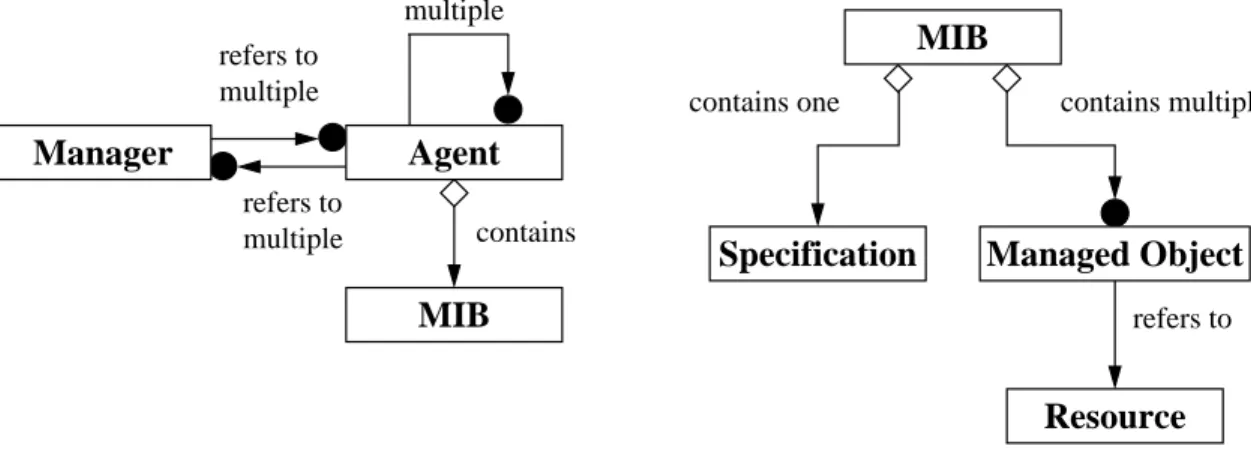
Note that the relationships between Managers and Agents must be maintained adequately.
One approach is to have each Manager and Agent maintain their own list of collaborating
opposites, resulting in a rather inflexible update scheme. Instead, the Mediator [3] pattern may be
used to maintain all these relationships. Alternatively, the Remote Operation pattern may be used
to provide location transparency. Yet another approach is to use the Broker pattern discussed in
[2]. In this article, we will only cover the Remote Operation pattern, the solution we adopted in
Layla for its simplicity of implementation. But before, we shall take a closer look at the Managed
Object pattern governing the MIBs.
Figure 4: Structure of Manager-Agent (left) and Managed Object patterns (right). contains MIB refers to multiple refers to multiple refers to multiple contains multiple contains one refers to MIB Specification Resource Managed Object Manager Agent
MANAGED OBJECT PATTERN
You need to manage a large collection of resource entities. Each entity has an interface that may
somewhat vary from the interfaces of the other entities, resulting in a great number of different
interfaces with somewhat similar features. Such variation can be caused by the nature of the
entities, their manufacturers, etc. In addition, there is often a hierarchical and/or a containment
relationship amongst the entities being managed. The problem here is to provide a unified interface
for representing and controlling the resources, while still allowing for a fine degree of control.
Although the resources may have diverging interfaces, they need to be controlled in a uniform way,
and the relationships amongst them should be taken into account.
The proposed solution is to use an instance of the Adapter pattern [3] for each individual
Resource, in order to translate its particular interface into one shared by all Resource instances. We
call this Adapter a Managed Object. It enables management operations to be performed using a
single interface. The Managed Object instances can then be aggregated using the Composite
pattern [3]. The composition is called a MIB (Management Information Base). It is sensitive to all
the relationships that usually exist among the Resource instances, such as hierarchy and
containment. The layout and interface of the MIB follows a Specification which describes the
content of the MIB to the outside world (see Figure 4, right).
The result is a flexible structure that appropriately mirrors the organization of the Resource
instances and that uses a single interface for the management of these instances. An individual
Resource can be located by traversing the MIB (with the Iterator pattern and/or the Visitor pattern
[3]) and by applying operations on the Managed Object’s interface. It will in turn apply the
corresponding operations to the Resource using the appropriate interface. The Managed Object,
representing the Resource being managed, supplants the Resource’s specific interface with the
operations such as theVisitMe() operation in the Visitor pattern. The MIB acts as a repository
for all the management data and functionalities of the system.
The Managed Object pattern brings with it a number of benefits, but also some liabilities.
On the positive side, the MIB and the Managed Object instances offer a single interface. This
interface encapsulates the proprietary protocols of the Resource and simplifies the management of
the system. A managing application is then able to communicate with each and every Resource in
the MIB, regardless of its nature or particular characteristics.
On the downside, the Managed Object provides only indirect access to the Resources, thus
adding another level of indirection to the processing of management operations. This might
compromise the system’s performance, unless care is taken to keep the overhead to a minimum.
Note that the Managed Object must offer an interface that can gracefully support a large
variety of proprietary interfaces. It must allow for the access to internal parameters and support the
application of specific functions to the Resource. The Specification should express the details of
the MIB in a manner as neutral and as precise as possible. In this way, the interoperability of the
resource entities is ensured regardless of their underlying source or implementation.
REMOTE OPERATION PATTERN
In a distributed system, such as a client/server system, the client of an operation is often removed
from the location where that operation’s implementation actually resides. The client must then
access the implementation through a communication network. The problem here is to make a
remote operation invocation appear exactly the same as a local operation invocation, both to the
client and to the implementation. When attempting to solve this problem, the developer must deal
with a number of conflicting forces. For one thing, making a call across the network is inherently
Furthermore, both the client and server the application must be shielded from all network-specific
details.
The proposed solution is to encapsulate all network interactions in stub objects, both on the
Invoker’s (client) and the Performer’s (server) side. The Client Stub and the Server Stub
communicate with each other using Connection and Message instances that are specific to the
network under consideration. The Invoker and the Performer interact locally with their respective
Stubs (see Figure 5). The result is a system where the invocation of a remote operation is decoupled
from the network interactions needed to carry it out. This solution, referred to as Remote Operation
pattern, can be seen as a refinement of the Proxy pattern [3]. It further decouples the network
interactions from the Invoker and the Performer of the operation.
The Remote Operation pattern brings with it a number of benefits, but also some liabilities.
On the positive side, the Invoker and the Performer are shielded from the network. Neither knows
really if the invocation actually took place across the network or not. The Invoker doesn’t even
know where the operation is actually performed. To the Invoker, the whole business is no different
from invoking a method on a local object, in this case the Client Stub.
On the downside, a remote invocation takes longer than a local invocation. The time it takes
to fulfill a remote invocation depends on the amount of overhead in the Messages and the
bandwidth of the Connection. Furthermore, network errors may cause Messages to be lost. Some
error correction mechanism is thus required to make the whole design more reliable. Also, it is hard
to pass object references across process boundaries. The Client Stub and the Server Stub must
handle pointers as well as object instances in a way that the semantics of the operation are
DISCUSSION
The pattern system of Layla illustrates the application and refinement of the pattern catalog
presented in [3] for the NMI domain. Beyond this domain, the Layla patterns are relevant in the
realm of distributed systems in general [2]. The three key patterns discussed in this paper have been
used in various contexts. The Manager-Agent pattern can be found in both CMIS and SNMP, and
has been implemented in the OSIMIS [8] framework. The Managed Object pattern is used in CMIS
as well, whereas in SNMP it occurs but in a diluted form. The Remote Operation pattern, finally,
is being used in a number of interprocess protocols, such as CMIP and the protocol suite for X.400
electronic mail. Other implementations include Sun’s and HP’s remote procedure call libraries.
Future object-oriented frameworks in the NMI domain such as JMAPI [6] are likely to leverage
Figure 5: Structure of Remote Operation pattern. Invoker
Connection
Performer
Client Stub Server Stub
Send() Receive()
Message
Marshal() Unmarshal()
Request Response Error
Creation Referral Inheritance
these patterns, in case they implement CMIS or SNMP.
The current version of Layla is the result of several iterations, which seems to be quite
typical for pattern-based framework development. Our “pattern mining” was definitely influenced
by the NMI domain in that the numerous standards and tools of this domain inspired, and
sometimes impeded, our work. And we can but confirm the lessons learned from framework
development based on design patterns as reported elsewhere, for instance in [5, 11].
Layla is conceived as a pattern-based application framework. Its development
demonstrates that pattern-based frameworks can be built for the demanding NMI domain.
Experimentation with Layla makes us believe that pattern benefits such as flexibility, reusability,
and documentation value of the framework and the resulting applications can indeed be reaped.
Our experience suggests that the pattern-based architecture of Layla makes NMI development
considerably easier. We contend that the pattern system upon which Layla is built will be helpful
for other NMI framework builders and for NMI application developers alike.
ACKNOWLEDGEMENTS
This work was in part funded by the Ministry of Industry, Commerce, Science and Technology,
Québec, under the IGLOO project organized by the Centre de Recherche Informatique de Montréal
(CRIM), by Teleglobe Canada Inc., and by the National Sciences and Research Council of Canada.
The authors wish to express their gratitude to Brahim ould Bah for implementing several examples,
and to Teleglobe Canada Inc. for allowing us access to their premises and equipments. Our thanks
also go to our colleague Gregor von Bochmann, scientific leader of the IGLOO project, for his
insightful comments during the course of our project. We would also like to thank Doug Schmidt,
our PLoP’96 shepherd, and our colleagues from the PLoP’96 Writers’ Workshop No. 4 for their
REFERENCES
[1] AT&T Bell Laboratories. BaseWorX Application Platform (AP): Application Management
Reference Guide, 1994.
[2] Frank Buschmann, Regine Meunier, Hans Rohnert, Peter Sommerlad, and Michael Stal.
Pat-tern-Oriented Software Architecture - A System of Patterns. John Wiley and Sons, 1996.
[3] Erich Gamma, Richard Helm, Ralph Johnson, and John Vlissides. Design Patterns. Elements
of Reusable Object-Oriented Software. Addison-Wesley, 1994.
[4] Hewlett Packard. HP OpenView Distributed Management Developer’s Guide, September 1994.
[5] Hermann Hüni, Ralph Johnson, and Robert Engel. A framework for network protocol soft-ware. In Proceedings of the Conference on Object-Oriented Programming: Systems,
Lan-guages and Applications (OOPSLA’95), pages 358–369, Austin, TX, September 1995.
[6] Javasoft (Sun Microsystems Inc.), Mountain View, CA. Java Management API, May 1997. Alpha Release Documentation.
[7] Rudolf K. Keller and Reinhard Schauer. Design components: Towards software composition at the design level. In Proceedings of the Twentieth International Conference on Software
Engineering , Kyoto, Japan, 1998. IEEE. to appear.
[8] George Pavlou, Graham Knight, Kevin McCarthy, and Saleem Bhatti. The OSIMIS plat-form: Making OSI management simple. In Adarshpal Sethi, Yves Raynaud, and Fabienne Faure-Vincent, editors, Integrated Network Management IV, pages 480–493. Chapman and Hall, 1995.
[9] Marshall T. Rose. The Simple Book: An Introduction to Management of TCP/IP-based
Inter-nets. Prentice-Hall, Inc., Englewood Cliffs, NJ, 1991.
[10] Douglas C. Schmidt. Reactor: An object behavioral pattern for concurrent event demulti-plexing and event handler dispatching. In James O. Coplien and Douglas C. Schmidt, edi-tors, Pattern Languages of Program Design, chapter 9, pages 529–545. Addison-Wesley, 1995. (Reviewed Proceedings of the First International Conference on Pattern Languages of Programming (PLoP’95), Monticello, IL, 1994).
[11] Douglas C. Schmidt. Using design patterns to develop reusable object-oriented communica-tion software. Communicacommunica-tions of the ACM, 38(10):65–74, October 1995.
Box 1: APIs for network management interfaces. Manager Application Agent Application API API Managed Resources
In a typical network management system, the managed resources are grouped under an agent application and controlled remotely by a manager
application. The agent and the
manager use both an underlying API (application programming interface) to communicate with each other and to exchange management information. Commercially available APIs exhibit limitations that may be overcome by encapsulating them in an application framework.
Box 2: Documenting patterns and pattern systems.
Patterns capture the essence of successful solutions to recurring problems which arise when building software systems. They are usually documented, especially when grouped together in a catalog, in a common format, or template. A popular format is the one suggested by Gamma et al. [3]. The format consists of the sections: intent, motivation, applicability, structure, participants, collaborations among participants, consequences, implementation suggestions, known uses, and related patterns.
Patterns should be interwoven in pattern systems [2, 8] that describe how they are connected and how they complement each other. For some small and well-known domains, pattern systems have been devised to cover all and every aspect of importance in the domain, and thus could be called pattern languages. In most other domains, such as NMIs, patterns only cover certain aspects of software construction. However, as the pattern discipline matures, more pattern languages are likely to appear.
All new patterns found in Layla have been described using the format of Gamma et al. [3], and are available, together with further documentation of Layla, at http://
www.iro.umontreal.ca/labs/gelo/layla/. The individual pattern descriptions
comprise numerous hints and references to relevant patterns within and beyond Layla. The classification by their role (tactical or strategic) and scope (NMI-specific or general-purpose), together with the description of the interplay of the patterns in Layla applications, further describes the pattern system.
Box 3: Layla’s patterns at work.
Many network protocols such as Xcoop1 use network management functions to reserve and activate physical connections. Among the applications developed for validating the Layla framework, we have implemented an Xcoop agent for a transit system. The Xcoop agent and an associated mapper manager interact according to the Manager-Agent design pattern, with events being handled by the Reactor pattern. The agent contains the Xcoop MIB, a collection of 15 managed objects implemented using the Managed Object, Template Method, and
Inherited Behavior patterns. The managed objects are grouped using the Compositor pattern.
An implementation of the Abstract Factory pattern is used to connect the agent with the manager and to enable CMIP operations (implemented using the Remote Operation and the
Translator patterns). The manager sends M-GET requests to the top object in the agent’s
containment hierarchy with a scope designating the whole tree. When the agent receives such a request, it uses aCScope object (an implementation of the Visitor pattern) to enact the M-GET request in each and every managed object of the MIB. Each managed object gives rise to
anM-GET response message back to the mapper manager, which sorts them out and uses that
information to display a map of the MIB.
In building this application, the managed objects’ specifications must be written in GDMO and ASN.1. For implementing the managed objects, the agent, and the manager, much of the code is supplied by Layla, and only minor portions need to be defined by the developer, mostly through subclassing.
1 European ATM Pilot project. Xcoop Interface Specification for the ATM Pilot, May 1994.
Mapper Xcoop Manager Agent Xcoop MIB (15 managed objects) sends M-GET requests sends M-GET response messages contains