Representing Concerns in Source Code
byMartin P. Robillard
B.Eng. (Computer Engineering), ´Ecole Polytechnique de Montr´eal, 1997 M.Sc. (Computer Science), University of British Columbia, 1999
A THESIS SUBMITTED IN PARTIAL FULFILLMENT OF THE REQUIREMENTS FOR THE DEGREE OF
Doctor of Philosophy
in
THE FACULTY OF GRADUATE STUDIES (Department of Computer Science)
We accept this thesis as conforming to the required standard
The University of British Columbia
November 2003c
Abstract
Many program evolution tasks involve source code that is not modularized as a single unit. Furthermore, the source code relevant to a change task often implements different concerns, or high-level concepts that a developer must consider. Finding and understanding concerns scattered in source code is a difficult task that accounts for a large proportion of the effort of performing program evolution. One possibility to mitigate this problem is to produce textual documentation that describes scattered concerns. However, this approach is impractical because it is costly, and because, as a program evolves, the documentation becomes inconsistent with the source code.
The thesis of this dissertation is that a description of concerns, representing program structures and linked to source code, that can be produced cost-effectively during program investigation ac-tivities, can help developers perform software evolution tasks more systematically, and on different versions of a system.
To validate the claims of this thesis, we have developed a model for a structure, called concern graph, that describes concerns in source code in terms of relations between program elements. The model also defines precisely the notion of inconsistency between a concern graph and the corresponding source code, so that it is possible to automatically detect and repair inconsistencies between a description of source code and an actual code base.
To experiment with concern graphs, we have developed a tool, called FEAT, that allows devel-opers to iteratively build concern graphs when investigating source code, to view the code related to a concern, and to perform analyses on a concern representation. Using FEAT, we have evalu-ated the cost and usefulness of concern graphs in a series of case studies involving the evolution of five systems of different size and style. The results show that concern graphs are inexpensive to create during program investigation, can help developers perform program evolution tasks more systematically, and are robust enough to represent concerns in different versions of a system.
Contents
Abstract ii
Contents iii
List of Tables vi
List of Figures vii
Acknowledgments ix
1 Introduction 1
1.1 Concerns . . . 3
1.2 An Example of Program Evolution Involving Scattered Concerns . . . 5
1.3 Existing Support for Scattered Concerns . . . 10
1.4 Concern Graphs . . . 11
1.5 Overview of the Dissertation . . . 14
2 The Concern Graph Model 15 2.1 Design Goals . . . 15 2.2 Formal Representation . . . 16 2.2.1 Programs . . . 16 2.2.2 Fragments. . . 20 2.2.3 Concerns . . . 23 2.3 Analyses. . . 24 2.3.1 Concern Analysis. . . 24 2.3.2 Inconsistency Management. . . 25 2.4 Summary . . . 26
3 Tool Support for Concern Graphs 28 3.1 General Mapping Function for Java . . . 28
3.2 The Feature Analysis and Exploration Tool . . . 31
3.2.1 Usage Model . . . 32
3.2.2 User Interface. . . 33
4 Validation 46 4.1 Methodology . . . 47 4.2 AVID Study . . . 48 4.2.1 Theory . . . 48 4.2.2 Study Design . . . 49 4.2.3 Results . . . 51 4.2.4 Validity . . . 52 4.3 Jex Study . . . 52 4.3.1 Theory . . . 53 4.3.2 Study Design . . . 53 4.3.3 Results . . . 54 4.3.4 Validity . . . 56 4.4 Redback Study . . . 56 4.4.1 Theory . . . 56 4.4.2 Study Design . . . 56 4.4.3 Results . . . 57 4.4.4 Validity . . . 57 4.5 jEdit Study . . . 57 4.5.1 Theory . . . 58 4.5.2 Study Design . . . 58 4.5.3 Results . . . 61 4.5.4 Validity . . . 66 4.6 ArgoUML Study . . . 67 4.6.1 Theory . . . 67 4.6.2 Study Design . . . 67 4.6.3 Results . . . 69 4.6.4 Validity . . . 72 4.7 Summary . . . 73
5 Automating Concern Graph Creation 75 5.1 Investigation Transcripts . . . 76
5.2 Inference Algorithm. . . 77
5.2.1 Calculating Probabilities . . . 77
5.2.2 Calculating the Correlation Metric . . . 78
5.2.3 Generating Concerns . . . 79 5.3 Empirical Evaluation . . . 80 5.3.1 Implementation Status . . . 80 5.3.2 Configurations . . . 81 5.3.3 Studies . . . 81 5.3.4 Results . . . 82 5.3.5 Observations . . . 85 5.4 Summary . . . 87
6 Discussion 88
6.1 The Development and Evaluation of the FEAT Tool . . . 88
6.2 Training and the Use of FEAT . . . 89
6.3 Capturing System Behavior with Concern Graphs . . . 90
6.4 The Importance of a Good Seed . . . 91
6.5 Concern Interaction Analysis . . . 91
6.6 The Influence of Concern Graphs on the Evolution Process . . . 92
6.7 Future Work . . . 93
6.7.1 Automatic Concern Graph Construction . . . 93
6.7.2 Concern Databases . . . 93
6.7.3 Pattern-based Code Investigation. . . 94
6.7.4 Concern Graph-based Code Refactoring . . . 94
7 Related Work 95 7.1 Concern Code Location . . . 95
7.1.1 Cross-referencing Tools . . . 95
7.1.2 Program Slicing . . . 96
7.1.3 Feature Location Techniques . . . 97
7.1.4 Clustering Techniques . . . 99
7.2 Concern Documentation . . . 99
7.2.1 Textual Documentation. . . 100
7.2.2 Conceptual Modules . . . 100
7.2.3 Concern Visualization Tools . . . 101
7.2.4 Virtual Files. . . 101
7.2.5 Advanced Separation of Concerns Mechanisms . . . 101
7.3 Inconsistency Management . . . 102
8 Conclusions 104 Bibliography 118 Appendix A Relational Algebra 119 A.1 Notational Conventions . . . 119
A.2 Definitions. . . 119
Appendix B Relations in Java Programs 121 Appendix C Transcripts for the jEdit Case Study 123 C.1 Subject C1. . . 124
C.2 Subject C2. . . 125
C.3 Subject F1 . . . 127
List of Tables
4.1 Claims addressed by the different studies. . . 47
4.2 Characteristics of the different studies . . . 47
4.3 Concern completeness results. . . 55
4.4 Subject Characteristics . . . 63
4.5 Concern graph for the ArgoUML study . . . 69
4.6 Differences between classes of versions 0.11.4 and 0.13.4 of ArgoUML . . . 70
4.7 Overlap between studies and claims . . . 74
5.1 Configuration parameter values . . . 81
5.2 Characteristics of transcripts . . . 83
5.3 Results for Subject C1 . . . 83
5.4 Results for Subject C2 . . . 84
5.5 Results for Subject C3 . . . 84
5.6 Results for Subject J1 . . . 85
5.7 Results for Subject J2 . . . 85
C.1 View codes . . . 123
List of Figures
1.1 Concern scattering and tangling. . . 3
1.2 Sorting program . . . 4
1.3 The main window of the jEdit application . . . 6
1.4 The options window of the jEdit application . . . 7
1.5 Partial code in the fileLoadSaveOptionPane.java. . . 7
1.6 MethodAbstractOptionPane.save() . . . 8
1.7 MethodOptionGroup.save() . . . 9
1.8 Partial concern graph for SAVING WIDGET STATE . . . 12
1.9 Partial concern graph for SAVING WIDGET STATEand MANAGINGPROPERTIES . 13 2.1 Mapping function C1 . . . 18 2.2 Mapping function J1 . . . 18 2.3 Program P1 . . . 19 2.4 ModelP1J1 . . . 19 2.5 Mapping functionJ2 . . . 21 2.6 Program P2 . . . 22 2.7 ModelP2J2 . . . 22
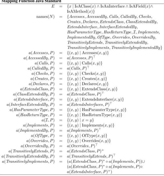
3.1 The mapping function Java Standard . . . 29
3.2 MethodOptionGroup.save() . . . 31
3.3 The Eclipse platform . . . 34
3.4 The FEAT Perspective. Area 1 holds the Concern Graph View. Area 2 holds the Participants, Interactions, and Inconsistencies Views. Area 3 holds the Projection and Relations Views. Area 4 holds the Java Editor. . . 35
3.5 The Concern Graph View . . . 35
3.6 The Participants View . . . 36
3.7 The Relations View . . . 37
3.8 A FEAT query . . . 37
3.9 Query results in the Projection View . . . 39
3.10 The Interactions and Relations Views . . . 39
3.11 The Inconsistency View. . . 41
3.12 The architecture of the FEAT tool . . . 42
3.13 Model extraction time. . . 44
4.1 Finding the important parts . . . 50
4.2 The anonymous class handling concern in Jex . . . 54
4.3 The ArgoUML application . . . 68
4.4 Representation of the inconsistent fragmentActionAddNote.SINGLETON accessed by ALLin the fragment viewer of the FEAT Inconsistency View . . . 71
4.5 MethodAbstractUmlModelFactory.initialize(Object)in ArgoUML ver-sion 0.11.4. . . 73
4.6 MethodAbstractUmlModelFactory.initialize(Object)in ArgoUML ver-sion 0.13.4. . . 73
5.1 Example investigation transcript . . . 77
5.2 Calculating probabilities . . . 78
Acknowledgments
If I completed this thesis and kept most of my sanity, it is only due to the many people who have supported me along the way.
My deepest thanks go to my supervisor, Gail Murphy. Gail has an amazing talent for blending encouragements, motivation, and advice in a subtle and clever mix that not only kept me on the right track, but also made me think I had something to do with it. I must thank Gail for teaching me, in the broadest sense possible, how to do research, and for being an example I will strive to follow for the rest of my career.
Thanks also to my senior colleague Rob Walker for his advice, honest criticism, and LaTeX templates, to Alex Brodsky for reviewing the formalism in the thesis, and to Jason Xu who, through his enthusiasm and hard work during his internship in the Software Practices Lab, has facilitated the evaluation of the tool-related aspects of the thesis.
The Department of Computer Science at UBC was in general a wonderful atmosphere for conducting research. Many thanks go the the numerous students, faculty, and staff members who have contributed to this thesis with their comments, help, and moral support.
I am also thankful to the members of my supervisory and examining committee who have gen-erously contributed their time and expertise: Will Evans, Alan Hu, Jim Little, Panos Nasiopoulos, Raymond Ng, and Barbara Ryder.
Finally, I thank my significant other, Dorothee, who was always understanding and stood with me through the rushes and absences (both mine and hers), and my parents, who have believed in me since day one.
My doctoral studies were financially supported by a Canadian NSERC postgraduate scholar-ship and a University of British Columbia Graduate Fellowscholar-ship.
MARTINP. ROBILLARD
The University of British Columbia November 2003
Chapter 1
Introduction
Useful programs keep changing. This simple observation, proposed as a law of program evolution dynamics by Belady and Lehman more than 25 years ago [12], is still true today. Although much has changed in the way we design and build programs, the need to repair, adapt, and enhance production software is still a reality for software development organizations [64,124]. The process of affecting modifications to a software system, often called the maintenance process [128], can vary between, and even within, organizations. Although many models have been proposed to structure the process of software maintenance [16,79,80,117,153], these models can typically be summarized by the three steps originally described by Boehm: understand the existing software, modify the existing software, and revalidate the modified software [14,15]. Thus, before performing a modification to a software system, developers must explore the system’s source code to find and understand the subset relevant to the change task. The large size of most production software, and the usual pressures on development and maintenance time-frames, render the program exploration activity a serious challenge for developers [17]. These factors make it unrealistic to expect developers to master the complete details of a system’s design and implementation prior to undertaking a modification. Rather, a developer must efficiently discover a sufficient amount of the structure and behavior of a program relevant to a modification. The discovery of this structure and behavior is a difficult task. Besides the basic difficulty of understanding source code [13,152], developers must usually consider conceptually-related subsets of the structure and behavior of a program addressing specific concerns. In this dissertation, we use the term “concern” to refer to any consideration a developer or team of developers might have about the implementation of a program. For example, in a file server application based on the File Transfer Protocol (or FTP server), one possible concern is the requirement to log every file transfer command issued by the client programs. The source code corresponding to this concern might consist of calls to functions such as log(String), and the implementation of these functions.
Unfortunately, it is often the case that the program code corresponding to a concern is not well encapsulated, and ends up being scattered across many modules [69]. For example, in the FTP server application described above, the logging code might be scattered throughout the im-plementation of all of the modules implementing file transfer commands. Scattered concerns pose an additional challenge to developers, who must reason about which pieces of code interact with which other ones to implement a concern, and about how different concerns interact with each other. The incomplete understanding of a scattered concern prior to a software modification can lead to incorrect or inefficient program modifications [74] or a modification not respecting an existing
de-sign [101]. The difficulty of locating and understanding scattered concerns is the first problem motivating the work described in this dissertation. This problem can be stated as follows.
Concern Location and Understanding Problem: It is difficult for developers to locate and under-stand the code implementing a concern when this code is not encapsulated within a single module.
Given the difficulty of locating and understanding the implementation of concerns relevant to a change task, it is desirable to capture, even partially, knowledge about the implementation of a concern. A representation of the knowledge about the implementation of a concern can help devel-opers perform modification tasks by supporting a more systematic investigation of the source code oriented along the lines of concerns, avoiding potentially erratic, “hit-and-miss” code investigation behavior. Additionally, preserving knowledge about the implementation of concerns allows other developers working on tasks involving the same concerns to capitalize on previous effort spent on similar modification tasks. The need to document scattered concerns to support software evolution was previously identified by Soloway et al. [73, 127]. Unfortunately, traditional documentation such as that proposed by Soloway suffers from the two principal drawbacks of any software doc-umentation: it is costly to produce and difficult to maintain consistent with the source code. This observation identifies the second problem this dissertation will address, the problem of concern documentation.
Concern Documentation Problem: It is difficult for developers to cost-effectively document con-cerns in source code and to keep the documentation consistent.
Because of this last problem, concerns are practically never documented, and developers tack-ling a software change task must usually start their investigation from scratch.
One way to address both of the problems described above is to integrate the production of documentation for concern code with the activity of locating and understanding the implementation of concerns, and by producing a concern description robust enough to be reusable with different versions of a code base. The thesis of this dissertation is that a representation for concerns in source code that can support the task of locating and understanding concern code, and that can represent concerns in more than one version of a program, can help developers evolve programs more systematically.
Thesis: A description of concerns, representing program structures and linked to source code, that can be produced cost-effectively during program investigation activities, can help developers perform software evolution tasks more systematically, and on different versions of a system.
In Section1.1we describe in more detail the concept of implementation concerns. This section is followed by a case study of program evolution involving scattered concerns (Section 1.2). The case study will serve as a running example motivating the work described in the dissertation. In Section 1.3, we provide a brief overview of tools and techniques that can partially address the problem of concern code location and understanding. In section1.4, we introduce the representation we propose to address both of the problems identified previously. Finally, Section1.5is an overview of the dissertation.
(a) Scattering (b) Tangling
Figure 1.1: Concern scattering and tangling.
1.1 Concerns
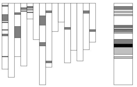
The idea of considering separate concerns in the implementation of software originates from Dijk-stra [33,34] and Parnas [99]. From these early works on system design and structured programming, the term “concern” has emerged as a general and flexible notion, intended to include anything a de-veloper might want to consider as a conceptual unit in a program. Examples include the implemen-tation of data stores, algorithms, the need for synchronization, and user interface considerations. Ideally, as a result of the design of a program, concerns should be neatly encapsulated within a module. For example, in a C [66] program requiring the sorting of integer arrays, the “sorting” concern can be encapsulated in a sortfunction. This way, the details of the sorting algorithm, such as whether a quick sort or bubble sort implementation is used, are confined to thesort func-tion [122]: modification of the implementation of the sorting algorithm will not require updating the callers of thesortfunction. Unfortunately, in practice, the concerns a developer must consider during program evolution are not always well separated, and their implementation is often found to be scattered through different modules, and, at the same time, tangled within one module [134].1 Figure1.1illustrates schematically the scattering and tangling of concerns. The illustrations use the SeeSoft program view [37], where white rectangles represent the source code for a module (e.g., a C file or a Java [48] class). In the representation of concern scattering (a), gray rectangles indi-cate source code relevant to a concern. This source code is scattered across multiple modules. In the representation of tangling (b), we show a single module. The module comprises two concerns, shown by the boxes in the two different shades of gray. These two concerns also have overlap-ping code, represented by the area in black. In other words, tangling involves the presence of code implementing different concerns within a module.
The scattering and tangling of concerns in source code is the consequence of four principal causes: inadequate design, the fundamental limitations of programming languages, emergence dur-ing program evolution, and code decay.
Inadequate Design Sometimes, scattered concerns result from a failure on the part of the initial developers of a system to create modules hiding implementation details associated with a con-cern [99]. The lack of concern separation results in a system that displays signs of scattering and tangling. For example, consider the partial C program of Figure1.2. Line 2 is the prototype of a function sorting an array of integers. This function takes as its third parameter a value for the size of a buffer used in the sorting of the array. Although the flexibility afforded by thebuffer size parameter might help to improve the memory consumption of the function, it has negative conse-quences for the evolvability of the system. Because details of the sort function implementation are exposed to client code (e.g., lines 78 and 490), a developer asked to improve the sorting algorithm will need to consider this client code as part of the sorting concern. A more evolvable design would have hidden the use of a buffer during sorting within thesortfunction.
1: /* Sort function */
2: int[] sort( int[] a, int n, int buffer_size ); ...
78: sorted_array = sort( current_array, 200, 600 ); ...
490: sorted_codes = sort( codes, 250, BUFFER_SIZE ); ...
Figure 1.2: Sorting program
In brief, even though guidelines exist to prevent unnecessary coupling between modules, de-sign is a human activity and as such is prone to errors and oversights that result in scattered concerns. Programming Language Limitations In some cases, competing design and implementation goals make it impossible to separate every concern with only the basic constructs of a programming lan-guage. This situation has been called the “tyranny of the dominant decomposition” [134]: a base decomposition of principal concerns is imposed on the system by the designer and the programming language, while secondary concerns must remain scattered. Sometimes, it is possible to mitigate the inflexibility of the dominant modular decomposition through the use of special-purpose design strategies, such as design patterns [46]. For example, the Visitor design pattern [46] is a solution to the problem of separating structure from behavior in hierarchical object collections. Although de-sign patterns can help address a small set of well-identified problems, they do not provide a solution for the majority of idiosyncratic modular decomposition problems. Extensions to popular program-ming languages have been proposed to help re-modularize scattered concerns into separate modules. These extensions usually come under the banner of advanced separation of concern mechanisms. Examples for the Java language include AspectJ [67,68], and the Hyperspaces approach [97,134] as embodied in the Hyper/J tool [96]. As we discuss in the rest of this section, there exists causes for concern scattering and tangling besides programming language limitations. While advanced sepa-ration of concern mechanisms can provide additional flexibility in separating some concerns, which can lead to less scattering, they cannot address all of the possible causes of concern scattering and
tangling. As a result, programs built with advanced separations of concerns mechanisms can also suffer from the presence of scattered concerns [83,85].
Emergence Another cause for the scattering and tangling of concern code is the emergence of concerns. Emerging concerns are concerns that did not exist at one stage of the development of a system, but that do need to be considered as a unit for the purpose of an evolution task. In other words, emerging concerns result from unforeseen changes. Although some flexibility for accom-modating emerging concerns can be achieved through the use of design for change paradigms [100] and design patterns [46], not all changes can be foreseen. Furthermore, designing for change in-evitably involves an increase in code size and design complexity which can be difficult to justify at development time. For this reason, some organizations are moving towards development practices, such as extreme programming [11], where design for change is avoided and replaced by periodical refactorings [43] of the design and implementation of a system to accommodate emerging concerns. In this latter case, the refactoring of a system is itself a program evolution task, usually requiring the consideration of scattered concerns.
Code Decay The last cause for the presence of scattered concerns in source code that we discuss is code decay. This phenomenon can be described with Lehman and Belady’s second law of program evolution dynamics, the Law of increasing entropy.
The entropy of a system (its un-structuredness) increases with time, unless specific work is executed to maintain or reduce it [71: p.169]
Strictly speaking, as digital media, programs are not altered by the sole effect of time. The real cause for the decay of programs is repeated maintenance [36]. The difficulty of locating and understanding the code relevant to a change, the absence of design documentation, the lack of adequate techniques for determining the impact of a modification [18], and time pressure all contribute to software modi-fications being performed by developers lacking a complete understanding of the implementation of the relevant concerns. As a result of such “ignorant surgery” [101], design constraints are violated and additional coupling between modules is introduced, often resulting in a further scattering and tangling of concerns in source code.
1.2 An Example of Program Evolution Involving Scattered Concerns
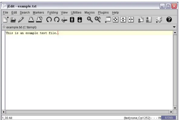
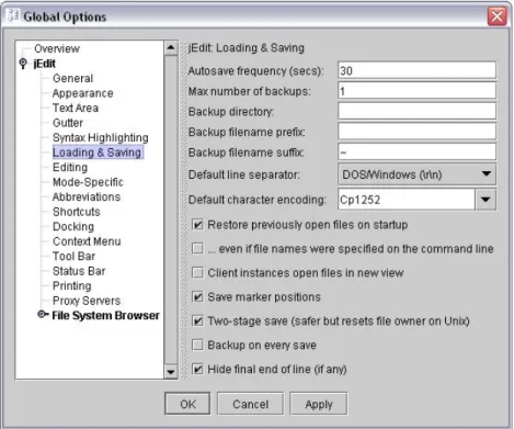
We illustrate the problem of locating, understanding, and documenting concerns during program evolution with an example of feature enhancement in a medium-size open-source project. The system we use for this example is the jEdit text editor.2 The jEdit application is written in Java and consists of approximately 65 000 non-comment, non-blank lines of source code, distributed over 301 classes in 20 packages. jEdit allows users to view and edit text files (called buffers), perform regular expression searches, etc. Figure 1.3 show the main window of jEdit. Among its many features, jEdit saves open file buffers automatically. Our example focuses on this autosave feature. In version 4.6-pre6, any changed and unsaved (or dirty) file buffer is saved in a special backup file at regular intervals (e.g., every 30 seconds). This frequency can be set by the user through an Options page brought up with a menu command in the application’s menu bar (see Figure 1.4). If jEdit
Figure 1.3: The main window of the jEdit application
crashes with unsaved buffers, the next time it is executed, it will attempt to recover the unsaved files from the autosave backups. A user can disable the autosave feature by specifying the autosave frequency as zero. However, this option is undocumented, and can only be discovered by inspecting the source code.
Let us assume the following modification request for the jEdit program is assigned to a devel-oper.
The application should be modified so that users can explicitly disable the autosave feature. The modified version should meet the following requirements.
1. jEdit shall have a check box labeled ”Enable Autosave” above the autosave fre-quency field in the Loading and Saving pane of the global options. This check box shall control whether the autosave feature is enabled or not.
2. The state of the autosave feature shall persist between different executions of the tool.
3. When the autosave feature is disabled, all autosave backup files for existing buffers shall be immediately deleted from disk.
4. When the autosave feature is enabled, all dirty buffers shall be saved within the specified autosave frequency.
5. When the autosave feature is disabled, the tool shall not attempt to recover from an autosave backup, if for some reason an autosave backup is present. In this case the autosave backup shall be left as is.
Figure 1.4: The options window of the jEdit application
Executing this modification request requires understanding different, scattered, implementation con-cerns. At first glance, without investigating the code, we can already identify potential concerns, such as the implementation of widgets on the options pane, the timing of the autosave event, the management of the buffer state (dirty or not), and the implementation of the autosave recovery operation.
public void _init()
{
/* Autosave interval */
autosave = new JTextField(jEdit.getProperty("autosave"));
addComponent(jEdit.getProperty("options.loadsave.autosave"),autosave); ...
}
public void _save()
{
Edit.setProperty("autosave",autosave.getText()); ...
}
Figure 1.5: Partial code in the fileLoadSaveOptionPane.java
Let us first look at some of the code managing the options pane, as shown in Figure1.5. The code partially shows two methods of the classLoadSaveOptionPane: init()and save(). Looking at this code, a developer can easily determine that the init() method is responsible for creating the text field used for the input of the autosave frequency. Examining the rest of the method (not shown here), it would be possible to establish that all the code for creating the widgets
for the option pane is located in the init() method. The WIDGET CREATION concern is thus
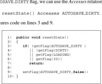
modularized, and the addition of a check box controlling the autosave feature requires the addition of code only to the init()method. Now let us look at the save(), method. Clearly, the method saves the state of a widget somewhere. Let us call this concern SAVING WIDGET STATE. In our scenario, it is necessary to understand this concern because changing the state of the check box controlling the autosave feature must take immediate effect. It is thus necessary to answer several questions:
• When is the save()method called()? • Where do properties get saved?
• How is the system notified that some properties have changed? • How is the state of a property accessed?
These are all questions that cannot be answered by simply examining the code of the save() method. The SAVING WIDGET STATEconcern is thus scattered. Attempting to answer the first
ques-tion by eliciting the call sites for the save()method reveals that it is called at a single point, within methodsave()of classAbstractOptionPane, the superclass ofLoadSaveOptionPane. The definition of thesave()method is shown in Figure1.6.
public void save()
{
if(initialized) _save();
}
Figure 1.6: MethodAbstractOptionPane.save()
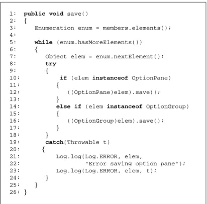
Far from elucidating the circumstances in which the save()is called, the identification of the call site reveals additional complexity for SAVING WIDGET STATE. First, one now must determine the circumstances in which thesave()method of classAbstractOptionPaneis called, and the circumstances in which theinitializedfield is true. SinceLoadSaveOptionPaneis a subclass ofAbstractOptionPane, additional investigation might also be required to determine whether methods of LoadSaveOptionPane can affect the state of the initialized field. Taking an additional step in the investigation of SAVING WIDGET STATE, we show the source code of method OptionGroup.save(), the method callingAbstractOptionPane.save()(Figure1.7). In this case we see that the call to thesavemethod (line 12) is embedded in some structure traversal code. Further investigation would show that detecting when the save()method is called requires eliciting relationships between at least nine methods and one field in six different classes. Reason-ing about all these interactions at once is impeded by the effects of both scatterReason-ing and tanglReason-ing. Because the concern is scattered, using an integrated development environment, the developer must understand and reason about the implementation of the concern by cycling through multiple edi-tor windows, each providing only a fragment of the information required to understand the concern. Because the implementation of the concern is tangled, each piece of code implementing the concern is cluttered with details not pertaining to the concern, such as structure traversal or error handling code (as exemplified in Figure1.7).
1: public void save() 2: {
3: Enumeration enum = members.elements(); 4:
5: while (enum.hasMoreElements())
6: {
7: Object elem = enum.nextElement();
8: try
9: {
10: if (elem instanceof OptionPane)
11: {
12: ((OptionPane)elem).save();
13: }
14: else if (elem instanceof OptionGroup)
15: { 16: ((OptionGroup)elem).save(); 17: } 18: } 19: catch(Throwable t) 20: { 21: Log.log(Log.ERROR, elem,
22: "Error saving option pane");
23: Log.log(Log.ERROR, elem, t);
24: }
25: }
26: }
Figure 1.7: MethodOptionGroup.save()
Going back to the four questions posed about the implementation of SAVING WIDGET STATE,
we observe that three of them relate to the management of a collection of property objects. This raises the additional question of whether properties are used only to store the state of the widgets, or are used as a form of global variables to store properties of jEdit. In the latter case, it would be important to gather a minimum understanding of how properties work to ensure that any modifi-cation involving properties management respects the existing design. As such, it might be useful to consider global properties management as a separate concern interacting with SAVING WIDGET
STATE. The presence of properties management code within SAVING WIDGET STATEillustrates
the important point that concerns do not exist in isolation. Concerns are integrated in an existing code base, they interact with other concerns, and the boundaries between different concerns and between a concern and the base code is not clearly defined. Reasoning about fuzzy boundaries for concerns adds an additional dimension to the difficulty of dealing with scattered concerns. In fact, studies have show that interacting concerns are often construed as major obstacles during program evolution tasks [8].
To summarize, a program evolution task such as the enhancement of the autosave feature in jEdit requires considering different concerns, such as saving the information contained in user interface widgets, and managing global properties of the application. Although concerns can often be simple and obvious concepts at an abstract level, their implementation is often scattered and tangled, making it difficult to fully understand their structure and behavior at once. Additionally, the boundaries of concerns are not clearly defined, and concerns often interact with other concerns, making it difficult to focus on a single concern at the time.
1.3 Existing Support for Scattered Concerns
Many program understanding and reverse engineering approaches have been developed to help a de-veloper discover the code related to a maintenance task. In this section we present a brief overview of the different types of approaches currently available to developers. Chapter7 provides a more comprehensive survey of techniques that can help developers find and manage the code implement-ing scattered concerns.
Searching and cross-referencing Lexical searching tools, such as grep [2], and cross-reference databases, such as the C Information Abstractor [25], can help a developer identify points in the code relevant to a concern, and, in the case of cross-reference databases, the relationships between the different points identified. Regular expression searches and cross-reference queries have also been integrated in software development environments [47,93,94,119]. However, the basic search-ing and cross-referencsearch-ing facilities of integrated environments follow a discover-and-discard model that provides little or no help for managing, understanding, and preserving the information discov-ered. At best, query results will be kept in a history list, allowing developers to revisit the results of searches. We argue that such minimalistic features cannot properly help developers document con-cerns in large, evolving code bases because they do not help the developer localize and synthesize the information related to the concern of interest [7]. Additionally, basic search mechanisms do not provide a means to document concerns across versions of a system. In brief, basic search features are not intended to, and do not, address the concern documentation problem.
Program Slicing Program slicing denotes a type of analysis intended to identify the parts of a program that may affect the values computed at some point of interest [138]. Slicing was originally defined as a static analysis technique [146], but many variants have since been proposed, including variants relying on dynamic information. Slicing and similar techniques can be used in maintenance activities to help find and manage the code related to a specific statement [45]. From the perspective of finding and understanding concerns, a major limitation of slicing is that only one type of concern can be identified: code related through a control- and data-flow criterion. Another drawback of slicing is that it does not discriminate between interesting and boilerplate code that would typically be ignored by developers (e.g., calls to a low-level library).
Reverse engineering and design recovery Reverse engineering [26] tools provide developers with views of the different elements in a program (e.g., classes, methods), and of the relations between them (e.g., Rigi [81]). Such tools can be construed as a visual representation of cross-reference tools. As such, they do not address the concern documentation problem.
Revision history A developer wishing to determine which subsets of the source code were af-fected by previous modifications can rely on data from a version control system such as RCS [137], SCCS [116], or CVS [22]. Although source code identified in this fashion can help point to inter-esting concerns, it often represents an incomplete picture of a concern. For instance, concerns that a developer needs to understand typically involve much more source code and program interactions than the code that was actually changed [8].
Dynamic analysis Other approaches to finding code relevant to one or more concerns use in-formation about a program’s execution. For example, using the Software Reconnaissance tech-nique [149,150], a developer determines the code implementing a feature by comparing a trace of the execution of a program in which a certain feature was activated to one where the feature was not activated. Software Reconnaissance and other dynamic analysis approaches like it, however, depend on an available suite of quality test cases. More importantly, the features expressible at the user level may not necessarily correspond to concerns a developer wishes to investigate. Often, developers must investigate code overlapping different features to understand enough of the system to respect existing design.
Concern analysis Finally, specialized program navigation and analysis tools have been proposed that to address the problem of scattered concerns. For example, conceptual Modules [7] allow a de-veloper to form logical modules composed of scattered lines of code, and support an investigation of the control- and data-flow relationships between the different logical units. The Aspect Browser [50] allows users to find and assess concerns based on which lines of code match user-specified regular expressions. Most of these tool address a very specific issue relating to scattered concerns, be it discovery and visualization (AspectBrowser), or analysis (Conceptual Modules). None of the ap-proaches proposed focus on documenting concern representations as a general, long-term artifact for program evolution.
1.4 Concern Graphs
To help developers locate, analyze, understand, and document scattered concerns during multiple evolution tasks on a program, we propose an approach that relies on a representation of concerns in source code as a principal artifact. We call our concern representation a concern graph. Simply put, a concern graph is a description of a subset of a program relevant to one or more concerns. However, a concern graph representation differs from an actual program in two important ways:
1. it mitigates tangling by abstracting the implementation details of the implementation of a concern, and
2. it mitigates scattering by making explicit the relationships between the different, scattered, pieces of code implementing a concern.
Let us illustrate these properties with the example of Section 1.2. Figure 1.7 shows the code of methodsave()of classOptionGroup. The subset of this method relevant to the SAVING WID
-GET STATEconcern is the call to methodsave()of classAbstractOptionPane(line 12). The
statement corresponding to this fact is reproduced here:
((OptionPane)elem).save();
Although simple, this statement contains information that is extraneous to our concern investigation. Specifically, in our case, it is not necessary to know that thesave()method is called on the object stored in theelemvariable. Moreover, we do not need to know that a down cast is required for this call to correctly type-check. The mere presence of this method call contributes to our understanding of the concern, and additional details resulting from the tangling of the call with the traversal of an enumeration is mere cluttering. Recognizing this problem, our intent for the concern graph
representation is to do away with the useless details, and store only the essential information, that OptionGroup.save()callsAbstractOptionPane.save().
The second difference between a concern graph and the source code is that a concern graph documents explicitly the relationships between the different elements of a concern. Returning to our example, we see that the method call statement shown above does not tell us where the implemen-tation of thesavemethod exists. Although the down cast toOptionPanetells us that is will be found in a class implementing or extendingOptionPane, cross-reference searches are required to obtain this information. In contrast, a concern graph stores this information explicitly. To complete our example, the information stored in a concern graph for the statement above includes:
OptionPane.save() CALLS AbstractOptionPane.save()
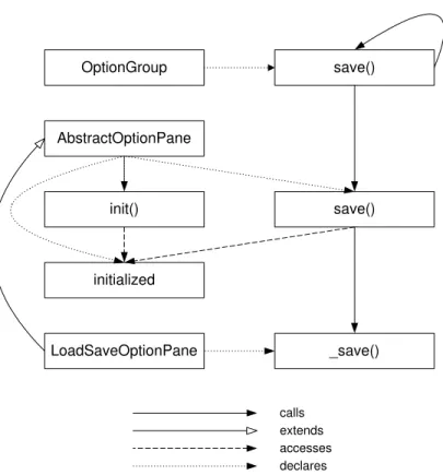
Of course, a concern graph is not limited to a single interaction between two elements (e.g., classes, methods, fields, variables, constants, etc.), but can comprise many different interactions, together forming a graph of relationships corresponding to the implementation of a concern. For example, Figure1.8shows the graph corresponding to the information about jEdit elicited in Section1.2.
LoadSaveOptionPane _save() AbstractOptionPane save() initialized OptionGroup save() init() calls extends accesses declares
Figure 1.8: Partial concern graph for SAVING WIDGET STATE
In the figure, nodes represent elements declared in jEdit (three methods, one field, and three classes), and edges represent the relationships between the elements. The graph provides a single and abstract view of the implementation of (part of) the SAVING WIDGET STATEconcern, enabling a developer to reason about only the code of interest.
A concern graph must be based on a program model that can be extracted automatically from either the source code or an intermediate representation of a program. As a result, a developer is able
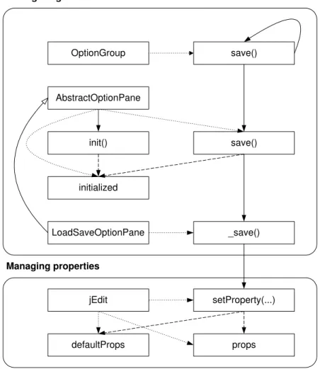
LoadSaveOptionPane _save() AbstractOptionPane save() initialized OptionGroup save() init() jEdit setProperty(...) defaultProps props
Saving widget state
Managing properties
Figure 1.9: Partial concern graph for SAVING WIDGET STATEand MANAGINGPROPERTIES
to manipulate and navigate a concern representation at a more abstract level than the source code without investing any effort to create the abstract representation. Automatically providing the part of a program model related to an element allows a concern graph to be augmented incrementally from related elements in the code base, potentially to include more than one concern. For example, we can augment the graph of Figure1.8to include some of the elements related to the management of properties (shown in Figure 1.9). The concern graph allows us to investigate the interactions between the two concerns. Of course, SAVING WIDGET STATEand MANAGING PROPERTIEScan also be specified as two different concern graphs, and merged at a later stage.
Finally, since concern graphs are intended to represent the source code relevant to a concern, there should exist an unambiguous mapping between the abstract representation and the source code. In other words, it should not be possible to specify information as part of a concern graph that cannot be automatically and unambiguously associated with source code. Inspection of the graphs in Figures1.8 and1.9 demonstrates that all of the structures present in the graph can be mapped back to the original code in jEdit: the nodes correspond to the declarations of classes, methods, and fields, and the edges correspond to more specific, sub-method information, such as method calls.
To summarize, the approach we propose to address the problems of concern location and un-derstanding and the problem of concern documentation relies on an abstract representation of
con-cerns in source code called a concern graph. A concern graph describes the structural links between different program elements potentially relevant to a concern, and supports a direct mapping to the corresponding source code.
1.5 Overview of the Dissertation
In the remainder of this dissertation, we present the details of the concern graph approach, demon-strate how eliciting and focusing on different concerns can help a developer perform software evo-lution tasks more systematically, and demonstrate how the information gathered about the imple-mentation of concerns can be reused with different versions of a system.
In Chapter2, we present a mathematical model for the definition of concern graphs on a pro-gram. This model is general and language-independent, and supports the definition of concerns by combining minimal descriptions, called fragments, into structures of increasing complexity. The concern graph model is also designed to support the detection and repair of inconsistencies between a concern graph and a program, making concern descriptions tolerant to the evolution of the cor-responding source code. The description of the concern graph model, and of the mechanism we designed to detect and repair inconsistencies between a concern graph and the source code, form the first two contributions of this dissertation.
To evaluate the practical value of representing concerns in source code, we instantiated our concern graph model for the Java language. In Chapter3, we provide the details of the concrete concern graph model we produced for use with Java programs, and we discuss the issues of usability and scalability related to our concrete model for Java. The presentation of the Java model and the accompanying discussion constitutes the third contribution of this dissertation. In Chapter3, we also describe the tool we implemented to support the use of concern graphs with Java programs. This tool, and the discussion of the challenges we addressed regarding its design and implementation, form the fourth contribution of this dissertation.
Based on the tool support for concern graphs described in Chapter3 we conducted five case studies to validate the thesis of this dissertation. In Chapter4, we describe each case study to show that concern graphs can help developers perform evolution tasks more systematically, are inexpen-sive to create, and are robust enough to be used on different versions of a system. The description of the design of the five case studies, and the discussion of the problems we have encountered, and of the steps we have taken to address them, constitutes the fifth contribution of our work.
The basic concern graph approach, as introduced in this chapter, relies on developers manu-ally building concern graphs during program investigation activities. However, one way to further reduce the cost of producing concern descriptions is through automation techniques. In Chapter5, we show how we can lower even further the cost of producing concern graphs by describing an algorithm for automatically inferring concern descriptions from the program investigation activities of a developer. The algorithm presented in Chapter5is the sixth contribution of this dissertation.
In Chapter6, we describe the main issues that arose during the development and investigation of the concern graph approach, summarize our views on the potential impact of concern graphs on the process of software evolution, and present a plan for future research involving concern graphs.
In Chapter 7, we put our research in perspective and highlight its novelty by providing an overview of the related work. Finally, in Chapter8, we conclude and summarize the contributions of the work described in this dissertation.
Chapter 2
The Concern Graph Model
Generally speaking, a concern is any consideration a developer or team of developers might have about the implementation of a subset of a program. A concern graph is an artifact intended to describe the source code that might be relevant to a concern. A concern graph is thus associated with a program. To explicitly state what can and cannot be expressed about a program in a concern graph, and the type of reasoning and analyses that developers can perform on concern graphs, we define a formal model of concern graphs.
2.1 Design Goals
The concern graph model is designed to meet several goals: to be language independent, flexible, precise, simple, robust, and tolerant to inconsistencies.
The first requirement is for the concern graph model to be language independent. The con-cept of an implementation concern is by no means limited to a particular programming language. Although mapping a concern to source code must inevitably involve the consideration of program-ming language syntax and semantics at some level, we wanted the general structure representing concerns to be language independent, to enable any reasoning performed at the level of the model to be applicable to concerns for code in any language.
The requirement for flexibility relates to the type of information that can be expressed about a program. For example, to capture concerns about the hierarchical organization of modules in a program, it is necessary only to capture information about the interactions between high-level declarations, such as classes or data structures. To capture concerns about general control-flow of an imperative program, it is necessary to represent interactions (calls) between methods or functions. Finally, to capture concerns about the flow of data during the execution of a program, it is necessary to include local variables in the model. Technically, any information about a program that can be produced statically (by a compiler or specialized analyzer) is available to describe part of a program. Examples include the basic declarative structure of a program, but also control- and data-flow information as represented by the program dependence graph (a program representation used in compiler optimization [40]), or the system dependence graph (used in software engineering applications such as testing [57]). We wanted a model flexible enough to be customizable for different levels of granularity of program information.
Our third requirement for a concern graph model is for it to be precise. Here, by precision, we mean that there should exist a non-ambiguous mapping between any structure present in a concern representation and the corresponding source code.
As much as possible, we wanted to ensure that the concern graph model remained simple and intuitive. In this way, developers working with a concern graph can determine the interactions between the different pieces of source code it represents without having to perform complicated calculations or logic reasoning.
The last two requirements, robustness and tolerance to inconsistencies, relate to the capability of concern graphs to represent concerns in evolving source code. Since a concern graph is essen-tially a representation of a subset of a code base, changes to this code base are bound to affect the representation. The requirement for robustness states that a concern graph should remain valid through minor code modifications. As such, it should not be dependent on non-essential and brittle aspects of the source code, such as line numbers or indentation. Also, major source code modifi-cations affecting the code represented by a concern graph should not invalidate the concern graph. Rather, it should be possible to detect any inconsistencies between a concern graph and its associ-ated code base and to use the consistent part of a concern graph, while preserving the inconsistent information to help repair the inconsistencies.
2.2 Formal Representation
We define concern graphs formally as a mathematical model based on relational algebra. Ap-pendixApresents the notation and important relational operations we use in the definition of the model.
2.2.1 Programs
Concern graphs must be able to represent a subset of a program that relates to a concern a developer has about the implementation of the program. As a result, the definition of a concern graph must be linked to an underlying program model that specifies which information about a program can be captured by a concern graph. This section deals with the modeling of programs. It forms the groundwork on which the concern graph model is built.
Our model of a program relies on the notion of a named relation. Named relations allow us to directly attach a meaning to a mathematical relation.
Definition 1 (Named Relation) A named relation Rn = (n, R) consists of a name nassociated
with a binary relationR.
We model a program as a set of elements declared in the program, and a set of named relations between these elements.
Definition 2 (Program Model) A program model (E, N) consists of a set of program elements
E ={e1, e2, ..., em}and a set of named relations overE,N ={Rn1, Rn2, ..., Rnk}.
This definition states that anything that can be known about a program in our model must be ex-pressed in terms of relations between elements. The generality of this definition allows the program model to apply to any representation of program code that can be expressed as a set of relations between elements. It applies equally to executable, intermediate, or source code. It applies to stand-alone programs as well as libraries. Finally, it applies to complete and correct programs as well as incomplete or incorrect programs.
For convenience in presentation, we provide a shorthand to represent the set of all relation names in a program model.
Definition 3 (Names Set) LetN ={Rn1, Rn2, ..., Rnk}be a set of named relations. We define the
set of all relation names inN as
names(N) ={n| ∃R : (n, R)∈N}.
This definition of a program model is equivalent to the definition of a labeled directed graph
(E,names(N),∆), withEa set of nodes,names(N)a set of labels, and∆⊆E×names(N)×E
a set of triples representing the labeled edges [102]. The name “concern graph” is thus intended to capture the idea of a graph of elements (nodes) and named relations (labeled edges) representing the subset of a program model addressing a concern.
Given a concrete programP in some programming language, a model of this program is ob-tained by applying a language-specific mapping functionM to the program. A model of program
P according to mapping functionM is represented byPM. Different mapping functions can be
defined for a single programming language.
Definition 4 (Mapping Function) LetPM = (E, N)be a program model. The mapping function M consists of:
• A criterion defining which elements declared in programP should be listed inE. • A set of relation names supported by the model.
• The definition of an analysis functiona(n, P) taking as parameters a relation namenand a programP, and returning a named relationRn ⊆ E×E representing the relationships
between elements ofP (meeting the mapping criterion), according to the semantics ofn. Because mapping functions are a means to obtain a program model from a concrete program, and do not support any reasoning about concern graphs, they will not be further formalized. All the formal reasoning for concern graphs involves modeled programs. In this dissertation, mapping functions are specified in a box, listing from top to bottom:
• the name of the mapping function,
• the criterion for inclusion of an elementxof programP intoE(the set of elements modeled), • the setnames(N)of supported relation names, and
• the definition of the analysis functiona(n, P).
By convention, analysis functions will be defined here using first-order logic. In practice, other notations can be used. As mentioned above, the definition of mapping functions is only an accessory issue which does not influence the characteristics of the concern graph model.
For example, Figure2.1presents a minimal mapping function for the C language modeling a program only as its call graph. The boolean functions used in the definition of the analysis function are normally defined in terms of the language specifications. For the purpose of the simple examples in this chapter, we assume that the behavior of the functions can be inferred from their name. Rela-tion names in a model are set in italics to distinguish them from the names of boolean funcRela-tions over
Mapping FunctionC1
E={x|IsAFunction(x)}
names(N) ={Calls,CalledBy}
a(Calls, P) ={(x, y)|Calls(x, y)}
a(CalledBy,P) =a(Calls, P)>
Figure 2.1: Mapping function C1
a program; boolean functions remain in normal type (see AppendixAfor the complete notational conventions).
The mapping function C1 states that the only information available about a program in the model is the program’s call graph, represented by the relations Calls and CalledBy (the transpose of the Calls relation). At this point it might seem superfluous to specify CalledBy as a relation in the mapping function since this relation represents redundant information, which can be obtained by a simple operation on the Calls relation. However, there exists an important semantic distinction between the two relations that can provide additional expressiveness in describing concerns. This issue is discussed in further details in Section2.2.2.
The application of a mapping functionM to a programP yields a program modelPM. The
application process consists in extracting the concrete set of program elementsEP and named
re-lationsNP.1 The elicitation is performed by applying the selection criterion to all the elements
declared inP, and by applying the analysis function toP for all relation names specified in the mapping function. In practice, this step is performed via standard static analyses, such as pars-ing [35], type-checking [3], control- or data-flow analysis [84, 91], and exception flow analy-sis [27,111,114,120,125].
We illustrate the process of producing a program model with an example of a simple Java pro-gram. In Java, in addition to methods and fields, classes can also declare other classes (called inner classes). These inner classes can extend any class visible in the scope of their declaration, creating intricate dependencies between different classes. In this example, we define a mapping function for the Java language capable of only representing the declaration and specialization relationships between classes. Figure2.2specifies this mapping function.
Mapping Function J1
E ={x|IsAClass(x)}
names(N) ={Declares,Extends,SuperclassOf,SubclassOf}
a(Declares, P) ={(x, y)|Declares(x, y)}
a(Extends, P) ={(x, y)|Extends(x, y)}
a(SubclassOf, P) =a(Extends, P)+
a(SuperclassOf, P) =a(SubclassOf, P)>
Figure 2.2: Mapping function J1
1Variables names for elements in a concrete program model resulting from the application of a mapping function to a program will be indexed with the name of the program. For abstract entities independent from a specific program model, the index is omitted.
This mapping function specifies that the only declarations considered in a modeled program are the classes declared in the program: interfaces, fields, methods, local variables, and other dec-larations are not modeled. Furthermore, the only relationships between classes documented by this model are whether a class declares another class (Declares), whether a class extends another class directly (Extends) or transitively (SuperclassOf ), or whether a class is transitively extended by another class (SubclassOf ). Like the mapping C1 of Figure2.1, the mapping J1 illustrates how relations can be defined in terms of other relations to add expressiveness to the model. In this case the use of the transpose and non-reflexive transitive closure operations support the definition of the SubclassOf relation. This example also illustrates an additional point: there are no constraints (such as symmetry) on the set of relations specified in a mapping function. This set can be customized to include only relations that offer a useful means of representing a program to users of the model. As such, we have purposefully excluded the transpose of the Extends relation as part of the model. If this relation had been deemed to be necessary to describe concerns, it could have easily been added to the model.
Let us now apply this mapping function to the program P1 of Figure 2.3. This application yields the model of Figure2.4. Program models are presented with a structure similar to mapping functions, but with a double line under the model name.
public class A { int aField; class B {} } class C extends A { void aMethod(){}; class D extends A {} class E extends D {} } Figure 2.3: Program P1 ModelP1J1 EP1 ={A,B,C,D,E} DeclaresP1 ={(A,B),(C,D),(C,E)} ExtendsP1 ={(C,A),(D,A),(E,D)} SubclassOfP1 ={(C,A),(D,A),(E,D),(E,A)} SuperclassOfP1={(A,C),(A,D),(D,E),(A,E)} Figure 2.4: ModelP1J1
This application results in the elements {A,B,C,D,E} being considered.2 Even though the program declares other elements, such as field A.aField and method C.aMethod(), these are
2In Java, classes that do not declare to extend any class extend the classjava.lang.Objectby default. For this reason, theObjectclass should be part ofEP1and the relations inNP1. We have left this detail out of our example for simplicity.
not included because they do not match the type specification for elements ofE according to the mapping function J1. Likewise, only pertinent relations between elements ofEP1are produced as a result of the application.
2.2.2 Fragments
With the conceptual foundations for modeling programs in place, we can now address the definition of a concern representation. Simply put, a concern graph is a description of a subset of a program model. Concern graphs are defined as a collection of small building blocks called fragments, which can be assembled to form concern descriptions of increasing complexity. A fragment describes a relationship between two sets of elements in a program model. It is the smallest unit of concern graph description. A fragmentfPis always defined on a program modelPM. A fragment consists of
an intent part and a program subset part. The intent of a fragment captures a high-level description of what one wishes to capture about a program (e.g., “all the subclasses of classC”). The program subset part captures the actual subset of the program corresponding to the intent (e.g., “classesA andB”).
To define the intent of a fragment, we use a domain set, a relation name, and a range set.3 For example, to specify a fragment representing a function call from functionato functionb, we would specify{a}as the domain,Calls as the relation name, and{b}as the range.
To describe the program subset part of a fragment, we need to define a projection operator on the objects defining the intent of a fragment and a program model.
Definition 5 (Projection Operator) LetPM = (EP, NP)be a program model,DomP ⊆EP and RanP ⊆EP be two subsets ofEP, andnP ∈names(NP)the name element of a named relation
Rn,P inNP.
proj(DomP, nP,RanP, PM) =DomP / RP .RanP.
In other words, the projection operator takes the intent of a fragment (a domain, relation name, and range) and a program model, and produces the relation corresponding to the intent. The distinction between the intent and program subset part of a fragment is important when one considers the evolution of programs. A fragment describing code for a program version P1 might still apply to a program version P2. The presence of the projection in the fragment supports answering this question precisely. The algorithms described in Section2.3.2detail how inconsistencies between a fragment and a program model can be detected and reconciled through the use of the projection.
We now have all of the tools required to formally define a fragment.
Definition 6 (Fragment) Let PM = (EP, NP) be a program model. Let DomP ⊆ EP be a
domain defined onP, RanP ⊆ EP a range defined onP, and nP ∈ names(NP). We define a
fragment asfP = (DomP,nP,RanP,ProjP), whereProjP = proj(DomP, nP,RanP, PM). We
say thatfP is defined onPM.
Given these definitions, we see that specifying a fragment consists in specifying a domain and range sets and a relation name, and applying the projection operator on a program model. The resulting
3The domain and range of a fragment are set variables, and are not to be confused with the relational operators defined in AppendixA.
fragment describes a subset of the program model. An important consideration when specifying fragments is the specification of the domain and range sets. Technically, for a program model
PM = (EP, NP), any specification resulting in a setS⊆EP constitutes a valid domain (or range).
In particular, we recognize three types of domain/range specifications: • A non-empty set of elements (e.g.,Dom ={A},Ran={A,C,D}).
• The universal domain (or range), represented by the setEP. SpecifyingEP as the domain or
range of a fragment will result in the projection including all elements in the domain of the specified relation.
• A subset specified as the range of a fragment projection. For example, to specify a do-main as all of the members of classAin a program modelPM, we would specifyDomP =
ran(proj({A},Declares, EP, PM))).
This flexibility in fragment specification affords us the capability to capture cohesive groups of relations as one fragment, and allows us to capture the semantic relationships between the relations as the intent of the fragment.
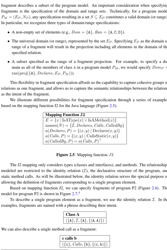
We illustrate different possibilities for fragment specification through a series of examples based on the mapping function J2 for the Java language (Figure2.5).
Mapping FunctionJ2
E ={x|IsAType(x)∨IsAMethod(x)}
names(N) ={I,Declares,Calls,CalledBy}
a(Declares, P) ={(x, y)|Declares(x, y)}
a(Calls, P) ={(x, y)|CallsStatic(x, y)}
a(CalledBy, P) =a(Calls, P)>
Figure 2.5: Mapping functionJ2
The J2 mapping only considers types (classes and interfaces), and methods. The relationships modeled are restricted to the identity relation (I), the declarative structure of the program, and static method calls. As will be illustrated below, the identity relation serves the special purpose of allowing the definition of fragments corresponding to a single program element.
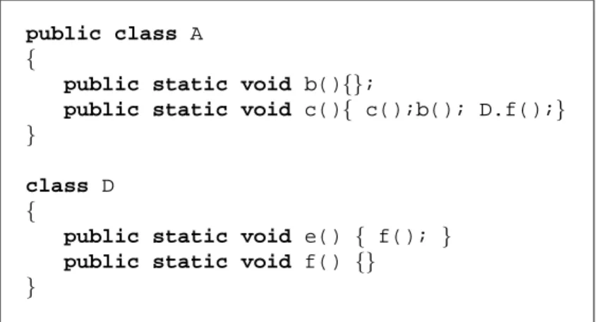
Based on mapping function J2, we can specify fragments of program P2 (Figure 2.6). The model for program P2 is shown in Figure2.7.4
To describe a single program element as a fragment, we use the identity relationI. In the examples, fragments are named with a phrase describing their intent.
Class A
({A},I,{A},{(A,A)})
We can also describe a single method call as a fragment: c calls b
({c},Calls,{b},{(c,b)})
public class A {
public static void b(){};
public static void c(){ c();b(); D.f();} }
class D {
public static void e() { f(); } public static void f() {}
} Figure 2.6: Program P2 ModelP2J2 EP2 ={A,b,c,D,e,f} IP2 ={(A,A),(b,b),(c,c),(D,D),(e,e),(f,f)} DeclaresP2={(A,b),(A,c),(D,e),(D,f)} CallsP2 ={(c,b),(c,c),(c,f),(e,f)} CalledByP2 ={(b,c),(c,c),(f,c),(f,e)} Figure 2.7: ModelP2J2
Fragments containing a single element in the domain and a single element in the range are called primitive fragments. If the relation represented by the primitive fragment actually exists in the model, the fragment projection is a set comprising a single pair formed by the single element in the domain and range. If the relation does not exist in the program model, the fragment projection is represented by the empty relationO. As a last example of primitive fragment, we can capture the fact that classDdeclares methodf:
D declares f
({D},Declares,{f},{(D,f)})
Obviously, primitive fragments do not exercise the full expressive power of the fragment structure. We can describe slightly more elaborate interactions using the universal range. For example, to capture all members of classA, we specify:
Members of A
({A},Declares, EP2,{(A,b),(A,c)})
If we apply the range operator to the projection of this fragment, we see that it correctly produces all the members of class A:
ran({(A,b),(A,c)}) ={b,c}.
We can also use the universal range to capture all the callers off. Callers of f
Even though relation CalledBy is simply the transpose of relation Calls, there is additional value in specifyingCalledByas part of a model, because it allows the use of the meaning of the relation to describe fragments. Without the CalledBy relation, it would be difficult to intuitively represent the intent to capture all of the calls to methodfin a single fragment.
Finally, it is possible to specify even more extensive fragments through the specification of a domain through a fragment. For example, to capture all calls by methods of classA, we can specify
Calls by methods of A
(ran(proj(({A},Declares, EP2, P2J2))),Calls, EP2,{(c,b),(c,c),(c,f)}) Obtaining the range of this last fragment’s projection, we get:
ran({(c,b),(c,c),(c,f)}) ={b,c,f}.
The last operation we define on fragments is the participants operation. For any fragment, it pro-duces a set of elements involved in the fragment.
Definition 7 (Participants) LetfP = (Dom,n,Ran,Proj)be a fragment.
participants(fP) = dom(Proj)∪ran(Proj)
2.2.3 Concerns
With fragments, it is possible to express different interactions between program elements. By ac-cumulating fragments, we can capture an increasingly large subset of a program model. However, a flat structure consisting of a list of fragments does not allow us to capture different and poten-tially related concerns. Often, when investigating source code, developers must reason about the code implementing concerns that are related because they are involved in a same task; other times, developers must consider the code implementing concerns that are related through a specialization relationship, where one concern addresses a specific subset of a more general concern. It is thus desirable to define a means of organizing fragments.
To address this requirement, our model includes a way to classify fragments into potentially overlapping sets. To do this, we define the notion of concern representation (or simply, concern) recursively, as a set of fragments and a set of subconcerns.
Definition 8 (Concern) LetPM be a program model. A concernCP = (FP, SP)defined onPM
is a tuple comprising a set of fragmentsFP ={f1, f2, ..., fn}and a set of concerns defined onPM,
SP ={s1, s2, ..., sm}.
The only constraint on the composition of fragments into a concern representation is that all of the fragments be defined on the same program model PM. We then say that a concern is defined on PM. Either or both ofF orScan be the empty set. A fragment inF can also be in any subconcern s ∈ S. Fragments and concerns are composed into other concerns based on the requirements of a user of the representation. A root concern, not included in any parent concern, represents the broadest abstraction for a particular concern. It is called a concern graph.