installation and
servicing
isar
(V3 Flue System)
Your Ideal installation and servicing guide
For details of document amendments, refer to page 3
When replacing any part on this appliance, use only spare parts that you can be assured conform to the safety and performance specification that we require. Do not use reconditioned or copy parts that have not been clearly authorised by Ideal Boilers.
HE24, HE30, HE35
DOCUMENT AMENDMENTS
Relevant Installation changes implemented in this book from Mod Level ... A02 to A03
(March 08)
Ideal Stelrad Group reserve the right to vary specification without notice
•
Page 14, Frame 9 - Unpacking
Change to Pack A contents with regard to Wall Mounting Template.
•
Page 15, Frame 10 - Packing Removal
Wall Mounting Template change.
•
Page 17, Frame 14 - Wall Mounting Template
isar HE24 HE30 HE35
Gas supply 2H - G20 - 20mbar
Gas Supply Connection Rc 1/2 (1/2” BSP female)
Injector Size Stereomatic 5.6mm dia. 5.7mm dia Inlet Connection Domestic Hot Water 15mm copper compression
Outlet Connection Domestic Hot Water 15mm copper compression Flow Connection Central Heating 22mm copper compression Return Connection Central Heating 22mm copper compression Flue Terminal Diameter mm (in) 100 (4)
Average Flue Temp-Mass Flow Rate (DHW) 66oC-10g/s 74oC - 12 g/s 82oC-14g/s
Maximum Working Pressure (Sealed Systems) bar (lb/in2) 2.5 (36.3)
Maximum Domestic Hot Water Inlet Pressure bar (lb/in2) 10.0 (145)
Minimum Domestic Hot Water Inlet Pressure bar (lb/in2) 0.5 (7)
Electrical Supply 230 V ~ 50 Hz.
Power Consumption 148 W 148 W 152 W
Fuse Rating External : 3A Internal : T3.15A L250 V Water content Central Heating litre (gal) 2.0 (0.44)
Domestic Hot Water 0.5 (0.11)
Packaged Weight kg (lb) 52 (115) 52 (115) 53 (117) Maximum Installation Weight kg (lb) 42.5 (94) 43 (95) 43.5 ( 96) Boiler Casing Size Height mm (in) 687 (27)
Width mm (in) 390 (15 3/8) Depth mm (in) 278 (11)
Table 1 - General Data
Note. Gas consumption is calculated using a calorific value of 38.7 MJ/m3 (1038 Btu/ft3) gross or 34.9 MJ/m3 (935 Btu/ft3) nett
To obtain the gas consumption at a different calorific value:
a. For l/s- divide the gross heat input (kW) by
the gross C.V. of the gas (MJ/m3)
b. For ft3/h - divide the gross heat input (Btu/h)
by the gross C.V. of the gas (Btu/ft3)
Key to symbols
GB = United Kingdom IE = Ireland (Countries of destination)
PMS= Maximum operating pressure of water
C13 C33 C53 = A room sealed appliance designed for connection via ducts to a horizontal or vertical terminal, which admits fresh air to the burner and discharges the products of combustion to the outside through orifices which, in this case, are concentric. The fan is up stream of the combustion chamber.
I2H = An appliance designed for use on 2nd Family gas, Group H only. * The value is used in the UK Government's Standard Assessment Procedure (SAP) for energy rating of dwellings. The test data from which
it has been calculated have been certified by a notified body.
CAUTION.
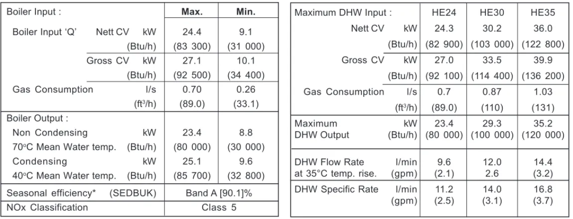
To avoid the possibility of injury during the installation, servicing or cleaning of this appliance care should be taken when handling edges of sheet steel components Table 2 - Performance Data - Central HeatingMaximum DHW Input : HE24 HE30 HE35 Nett CV kW 24.3 30.2 36.0 (Btu/h) (82 900) (103 000) (122 800) Gross CV kW 27.0 33.5 39.9 (Btu/h) (92 100) (114 400) (136 200) Gas Consumption l/s 0.7 0.87 1.03 (ft3/h) (89.0) (110) (131) Maximum kW 23.4 29.3 35.2 DHW Output (Btu/h) (80 000) (100 000) (120 000)
DHW Flow Rate l/min 9.6 12.0 14.4 at 35°C temp. rise. (gpm) (2.1) 2.6 (3.2) DHW Specific Rate l/min 11.2 14.0 16.8 (gpm) (2.5) (3.1) (3.7)
Table 3 - Performance Data - Domestic Hot Water
Boiler Input : Max. Min.
Boiler Input ‘Q’ Nett CV kW 24.4 9.1 (Btu/h) (83 300) (31 000) Gross CV kW 27.1 10.1 (Btu/h) (92 500) (34 400) Gas Consumption l/s 0.70 0.26 (ft3/h) (89.0) (33.1) Boiler Output : Non Condensing kW 23.4 8.8 70oC Mean Water temp. (Btu/h) (80 000) (30 000)
Condensing kW 25.1 9.6 40oC Mean Water temp. (Btu/h) (85 700) (32 800)
Seasonal efficiency* (SEDBUK) Band A [90.1]% NOx Classification Class 5
Boiler size
G.C. Appliance No.
PI No.
(Benchmark No.)
HE24
47 348 31
87 BP 34
HE30
47 348 30
87 BP 34
HE35
47 348 29
87 BP 34
CONTENTS
Air Supply...8Benchmark Commissioning Checklist...66
Boiler Clearances...9
Boiler Exploded Diagram...13
Condensate Drain...10, 21-22 Electrical Connections...31
Electrical Supply...10
Extension Ducts - Fitting...19
Fault Finding...56-60 Flow Wiring Diagram...34
Flue Fitting...18
Flue Installation...8
Gas Safety Regulations...7
Gas Supply...8 Installation...12-37 Mandatory Requirements...7-10 Pump ...53 Safe Handling...6 Servicing...38-55 Short List of Parts...61
Thermostatic Radiator Valves...10
Water and Systems...8,10-12 Water Connections...28-29 Water Treatment...12
Wiring Diagrams...32-34
isar
Natural Gas only
Destination Country: GB, IEB
oiler Page Make and model ... 5Appliance serial no. on data badge ... 13
SEDBUK No. % ... 4
Controls Time and temperature control to heating ... 32
Time and temperature control to hot water ... 32
Heating zone valves ... n/a TRV's ... 10
Auto bypass ... 10
Boiler interlock ... 10
For all boilers Flushing to BS.7593 ... 12
Inhibitor ... 12
Central heating mode Heat input ...to be calculated For assistance see Technical Helpline on the back page Page Burner operating pressure ... n/a Central heating flow temp. ... measure and record Central heating return temp. ... measure and record For combination boilers only Scale reducer ... n/a Hot water mode Heat input ... to be calculated Max. operating burner pressure ... n/a Max. operating water pressure ... measure & record Cold water inlet temp ... measure & record Hot water outlet temp. ... measure & record Water flow rate at max. setting ... measure & record For condensing boilers only Condensate drain ... 21
For all boilers: complete, sign & hand over to customer
For GB, to comply with Building Regulations Part L1 (Part 6 in Scotland) the boiler should be fitted in accordance with the manufacturer's instructions. Self-certification that the boiler has been installed to comply with Building Regulations can be demonstrated by completing and signing the Benchmark Commissioning Checklist.
BENCHMARK COMMISSIONING CHECKLIST DETAILS
NOTE TO THE INSTALLER: COMPLETE
THE BENCHMARK COMMISSIONING
CHECKLIST AND LEAVE THESE
INSTRUCTIONS WITH APPLIANCE
INTRODUCTION
The isar range of boilers are wall mounted, full sequence, automatic spark ignition, low water content, fanned flue, high efficiency, condensing, combination gas boilers.
Note.Due to the high efficiency of the boiler a plume of water vapour will form at the terminal during operation.
Central heating (CH) output is fully modulating with a range of 8.8 to 23.4kW (30,000 to 80,000 Btu/h)
Instantaneous domestic hot water (DHW) output is also fully modulating with a maximum of :
HE24 24.4kW (80,000 Btu/h) HE30 29.3kW (100,000 Btu/h) HE35 35.2kW (120,000 Btu/h)
The boiler is supplied fully assembled with DHW plate heat exchanger, diverter valve, circulating pump, pressure gauge, safety valve and CH expansion vessel.
Variable CH and DHW temperature controls are fitted on the user control and the boiler features a DHW preheat facility.
The boiler casing is of white painted mild steel with the user controls capable of being mounted remotely from the boiler if the option is required. The boiler temperature controls are visible at the bottom RHS of the front panel.
The heat exchanger is of cast aluminium.
The boiler is suitable for connection to fully pumped, sealed water systems ONLY. Adequate arrangements for completely draining the system by provision of drain cocks MUST be provided in the installation pipework. Pipework from the boiler is routed downwards as standard, but may be routed upwards behind the boiler using the stand-off frame (supplied in a separate kit).
OPERATION
With no demand for CH, the boiler fires only when DHW is drawn off, or periodically for a few seconds without any DHW draw-off, in order to maintain the DHW calorifier in a heated condition.
When there is a demand for CH, the heating system is supplied at the selected temperature of between 30 oC and 82oC, until DHW is drawn off.
The full output from the boiler is then directed via the diverter valve to the plate heat exchanger to supply a nominal DHW draw-off of
HE24 9.6 l/min at 35 oC temperature rise.
HE30 12 l/min at 35 oC temperature rise.
HE35 14.4 l/min at 35 oC temperature rise.
The DHW draw off rate specified above is the nominal that the boiler flow regulator will give. Due to system variations and seasonal temperature fluctuations DHW flow rates/temperature rise will vary, requiring adjustment at the draw off tap.
At low DHW draw-off rate the maximum temperature is limited to 65 oC by the
modulating gas control.
Refer also to Frame 1 - 'Boiler Water Circuit Diagrams'
The boiler features a comprehensive diagnostic system which gives detailed information on the boiler status when operating, and performance of key components to aid commissioning and fault finding.
SAFE HANDLING
This boiler may require 2 or more operatives to move it to its installation site, remove it from its packaging base and during movement into its installation location. Manoeuvring the boiler may include the use of a sack truck and involve lifting, pushing and pulling.
Caution should be exercised during these operations.
Operatives should be knowledgeable in handling techniques when
performing these tasks and the following precautions should be considered: • Grip the boiler at the base.
• Be physically capable.
• Use PPE as appropriate, e.g. gloves, safety footwear.
1
BOILER WATER
CIRCUIT DIAGRAMS
Central Heating CircuitExpansion vessel Automatic air vent Gas valve Plate heat exchanger Pump Safety relief valve Condensate 'S' trap Diverter valve Water pressure gauge Sump Fan Burner CH Flow Gas Condensate drain Discharg pipe CH Return
Domestic Hot Water Circuit
Expansion vessel Automatic air vent Heat exchanger Gas valve Pump Safety relief valve Condensate 'S' trap Diverter valve Water pressure gauge Sump Fan Burner DHW Hot out Gas Condensate drain Discharge pipe nm8763 DHW Cold in Plate heat exchanger Heat exchanger
During all manoeuvres and handling actions, every attempt should be made to ensure the following unless unavoidable and/or the weight is light. • Keep back straight.
• Avoid twisting at the waist.
• Avoid upper body/top heavy bending. • Always grip with the palm of the hand. • Use designated hand holds.
• Keep load as close to the body as possible. • Always use assistance if required.
SAFETY
Current Gas Safety (installation and use) regulations or rules in force:
The appliance is suitable only for installation in GB and IE and should be installed in accordance with the rules in force. In GB, the installation must be carried out by a CORGI
Registered Installer. It must be carried out in accordance with the relevant requirements of the:
• Gas Safety (Installation and Use) Regulations
• The appropriate Building Regulations either The Building Regulations, The Building Regulations (Scotland), Building Regulations (northern Ireland).
• The Water Fittings Regulations or Water byelaws in Scotland.
• The Current I.E.E. Wiring Regulations.
Where no specific instructions are given, reference should be made to the relevant British Standard Code of Practice. In IE, the installation must be carried out by a Competent Person and installed in accordance with the current edition of I.S.813 "Domestic Gas Installations", the current Building Regulations and reference should be made to the current ETCI rules for electrical installation.
Detailed recommendations are contained in the following British Standard Codes of Practice:
BS. 5440:1 Flues (for gas appliances of rated input not exceeding 70 kW).
BS. 5440:2 Ventilation (for gas appliances of rated input not exceeding 70 kW).
BS. 5449 Forced circulation hot water systems.
BS. 5546 Installation of gas hot water supplies for domestic purposes (2nd Family Gases)
BS. 6798 Installation of gas fired hot water boilers of rated input not exceeding 70 kW.
BS. 6891 Low pressure installation pipes.
Health & Safety Document No. 635. The Electricity at Work Regulations, 1989.
The manufacturer’s notes must NOT be taken, in any way, as overriding statutory obligations.
IMPORTANT. These appliances are CE certificated for safety and performance. It is, therefore, important that no external control devices, e.g. flue dampers, economisers etc., are directly connected to these appliances unless covered by these Installation and Servicing Instructions or as otherwise
recommended by Ideal Stelrad Group in writing. If in doubt please enquire.
Any direct connection of a control device not approved by Ideal Stelrad Group could invalidate the certification and the normal appliance warranty. It could also infringe the Gas Safety Regulations and the above regulations.
SAFE HANDLING OF SUBSTANCES
Care should be taken when handling the boiler insulation panels, which can cause irritation to the skin. No asbestos, mercury or CFCs are included in any part of the boiler or its manufacture.
LOCATION OF BOILER
The boiler must be installed on a flat and vertical wall, capable of adequately supporting the weight of the boiler and any ancillary equipment.
The boiler may be fitted on a combustible wall and insulation between the wall and the boiler is not necessary, unless required by the local authority.
For electrical safety reasons there must be no access available from the back of the boiler.
The boiler must not be fitted outside. Timber Framed Buildings
If the boiler is to be fitted in a timber framed building it should be fitted in accordance with the Institute of Gas Engineering document IGE/UP/7:1998.
Bathroom Installations
This appliance is rated IP20.
The boiler may be installed in any room or internal space, although particular attention is drawn to the requirements of the current IEE (BS.7671) Wiring Regulations and, in Scotland, the electrical provisions of the building regulations applicable in Scotland, with respect to the installation of the boiler in a room or internal space containing a bath or shower. For IE reference should be made to the current ETCI rules for electrical
installations and I.S. 813:2002.
If the appliance is to be installed in a room containing a bath or shower then, providing water jets are not going to be used for cleaning purposes (as in communal baths/showers), the appliance can be installed in Zone 3, as detailed in BS.7671.
Compartment Installations
A compartment used to enclose the boiler should be designed and constructed specially for this purpose.
An existing cupboard or compartment may be used, provided that it is modified for the purpose.
In both cases, details of essential features of cupboard / compartment design, including airing cupboard installation, are to conform to the following:
z BS 6798 (No cupboard ventilation is required - see ‘Air Supply’ for details).
z The position selected for installation MUST allow adequate space for servicing in front of the boiler.
OPTIONAL EXTRA KITS
z Flue Extension Ducts. (1000mm long). HE24-upto 6m
HE30-upto 6m HE35-upto 3m
z Flue Finishing Kit.
z 90o Elbow Kit (maximum per installation). HE24-upto 4 elbows
HE30-upto 4 elbows HE35-upto 2 elbows
z 45o Elbow Kit (maximum per installation). HE24-upto 4 elbows
HE30-upto 4 elbows HE35-upto 2 elbows
z Roof Flue Kit (to a maximum of 7.5m).
z Powered Vertical Flue Kit (5m primary and 17m secondary is a typical maximum length. For alternative details refer to Powered Vertical Instructions).
z High Level Flue Outlet Kits z Flue Deflector Kit
z Weather Collar
z Twin Fluing Kits (up to a maximum of 60m combined total flue and airducts)
z Horizontal Flue Terminal 600mm long z Remote User Controls Kit
z Boiler Stand-off Kit z Siphon Kit
z Valve Cover Kit z Contensate Pump Kit
z For the minimum clearances required for safety and subsequent service, see the wall mounting template and Frame 2. In addition, sufficient space may be required to allow lifting access to the wall mounting plate.
GAS SUPPLY
The local gas supplier should be consulted, at the installation planning stage, in order to establish the availability of an adequate supply of gas. An existing service pipe must NOT be used without prior consultation with the local gas supplier. The boiler MUST be installed on a gas supply with a governed meter only.
A gas meter can only be connected by the local gas supplier or by a CORGI registered engineer. In IE by a competent person. An existing meter should be checked, preferably by the gas supplier, to ensure that the meter is adequate to deal with the rate of gas supply required.
N.B. The principle of the 1:1 gas valve ensures that the isar HE range is able to deliver it’s full output at inlet pressures down to 14mb. However if dynamic pressures below 20mb are experienced ensure this is adequate for ALL other gas
appliances in the property.
IMPORTANT.
Installation pipes must be fitted in accordance with BS.6891. In IE refer to IS.813:2002. Pipework from the meter to the boiler MUST be of an adequate size, i.e. no longer than 20m and not less than 15mm O.D.
The complete installation MUST be tested for gas soundness and purged as described in the above code.
FLUE INSTALLATION
Pluming will occur at the terminal so terminal positions where this could cause a nuisance should be avoided.
The flue must be installed in accordance with the recommendations of BS. 5440-1: 2000.
In IE refer to I.S. 813:2002.
The following notes are intended for general guidance:
1. The boiler MUST be installed so that the terminal is exposed to external air.
2. It is important that the position of the terminal allows the free passage of air across it at all times.
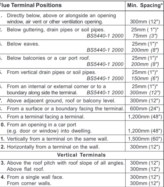
3. Minimum acceptable spacing from the terminal to obstructions and ventilation openings are specified in Table 4.
4. Where the lowest part of the terminal is fitted less than 2m (6'6") above a balcony, above ground or above a flat roof to which people have access then the terminal MUST be protected by a purpose designed guard.
Terminal guards are available from boiler suppliers. (Ask for TFC flue guard model no. K6 - round, plastic coated). In case of difficulty contact:
Grasslin (UK) Ltd. Tel. + 44 (0) 01732 359 888 Tower House, Vale Rise Fax. + 44 (0) 01732 354 445 Tonbridge. Kent TN9 1TB www.tfc-group.co.uk Ensure that the guard is fitted centrally.
5. The flue assembly shall be so placed or shielded as to prevent ignition or damage to any part of any building.
6. The air inlet/products outlet duct and the terminal of the boiler MUST NOT be closer than 25mm (1") to combustible material. Detailed recommendations on the protection of combustible material are given in BS. 5440-1:2000.
IMPORTANT. It is absolutely essential to ensure, in practice, that products of combustion discharging from the terminal cannot re-enter the building or any other adjacent building through ventilators, windows, doors, other sources of natural air infiltration, or forced ventilation / air conditioning.
If this should occur the appliance MUST be turned OFF, labelled as 'unsafe' until corrective action can be taken.
TERMINAL
The terminal assembly can be adapted to accommodate various wall thicknesses. Refer to Frame 12 .
AIR SUPPLY
It is NOT necessary to have a purpose-provided air vent in the room or internal space in which the boiler is installed. Neither is it necessary to ventilate a cupboard or compartment in which the boiler is installed, due to the low surface temperatures of the boiler casing during operation; therefore the requirements of BS 6798, Clause 12, and BS 5440:2 may be disregarded.
WATER CIRCULATION SYSTEM
IMPORTANT.
A minimum length of 1 metre of copper pipe MUST be fitted to both flow and return connections from the boiler before connection to any plastic piping.
The central heating system should be in accordance with BS.6798 and, in addition, for smallbore and microbore systems, BS.5449.
WATER TREATMENT - see Frame 6 * Only one reduction down to 25mm is allowable per installation
otherwise BS5440-1 2000 dimensions must be followed.
Flue Terminal Positions Min. Spacing*
1. Directly below, above or alongside an opening
window, air vent or other ventilation opening. 300mm (12") 2. Below guttering, drain pipes or soil pipes. 25mm ( 1")*
BS5440-1 2000 75mm (3")
3. Below eaves. 25mm (1")*
BS5440-1 2000 200mm (8")
4. Below balconies or a car port roof. 25mm (1")*
BS5440-1 2000 200mm (8")
5. From vertical drain pipes or soil pipes. 25mm (1")*
BS5440-1 2000 150mm (6")
6. From an internal or external corner or to a 25mm (1")* boundary along side the terminal. BS5440-1 2000 300mm (12")
7. Above adjacent ground, roof or balcony level. 300mm (12") 8. From a surface or a boundary facing the terminal. 600mm (24") 9. From a terminal facing a terminal. 1,200mm (48") 10.From an opening in a car port
(e.g. door or window) into dwelling. 1,200mm (48") 11.Vertically from a terminal on the same wall. 1,500mm (60") 12.Horizontally from a terminal on the wall. 300mm (12")
Vertical Terminals
13.Above the roof pitch with roof slope of all angles. 300mm (12") Above flat roof. 300mm (12") 14.From a single wall face. 300mm (12") From corner walls. 300mm (12")
nm8758
2
BOILER DIMENSIONS, SERVICES & CLEARANCES
all dimensions in mm (in)The boiler connections are made on the boiler piping frame. Refer to Frames 32-34.
The following minimum clearances must be maintained for operation and servicing.
Additional space will be required for installation, depending upon site conditions.
Side and Rear Flue
a. Provided that the flue hole is cut accurately, e.g. with a core drill, the flue can be installed from inside the building where wall thicknesses do not exceed 600mm (24").
Front clearance
The minimum front clearance when built in to a cupboard is 5mm (1/4") from the cupboard door but 450mm (17 3/4") overall
clearance is still required, with the cupboard door open, to allow for servicing.
N.B. The boiler will not fit into a standard depth wall unit. In order for it to do so the plastic fascia should be removed. See Frame 44.
*
Bottom clearanceBottom clearance after installation can be reduced to 5mm. However, 100mm must be available for servicing.
Where the space into which the boiler is going to be installed is less than the length of flue required the flue must be fitted from the outside.
Installation from inside ONLY
b. If a core boring tool is to be used inside the building the space in which the boiler is to be installed must be at least wide enough to accommodate the tool.
REAR FLUE ONLY
MIN. Top clearance required = 145 mm (5 3/4")
SIDE FLUE ONLY
Horizontal length of flue Top clearance from centre line of boiler required (MIN.)
to outside wall Dim. A HE24 HE30 HE35
0.5 m 0.5 m 0.5 m 160 mm (6 5/16") 1.0 m 1.0 m 1.0 m 170 mm (6 11/16) 1.5 m 1.5 m 1.5 m 185 mm (7 1/4") 1.5 m 1.5 m 1.5 m 200 mm ( 7 7/8") 2.5 m 2.5 m 2.5 m 210 mm (8 1/4") 3.0 m 3.0 m 3.0 m 225 mm (8 7/8") 3.5 m 3.5 m N/A 250 mm (9 7/8") 4.0 m 4.0 m N/A 260 mm (10 1/4") 4.5 m 4.5 m N/A 265 mm (10 7/16") 5.0 m 5.0 m N/A 275 mm (10 13/16") 5.5 m 5.5 m N/A 290 mm (11 3/8") 6.0 m 6.0 m N/A 300 mm (11 13/16")
General
1. The installation must comply with all relevant national and local regulations.
2. The installation should be designed to work with flow temperatures of up to 82 oC.
3. All components of the system must be suitable for a working pressure of 3 bar and temperature of 110 oC. Extra care should be taken in making all connections so that the risk of leakage is minimised.
The following components are incorporated within the appliance:
a. Circulating pump.
b. Safety valve, with a non-adjustable preset lift pressure of 3 bar.
c. Pressure gauge, covering a range of 0 to 6 bar.
d. An 8-litre expansion vessel, with an initial charge pressure of 0.75 bar.
4. 'Make-up' Water. Provision must be made for replacing water loss from the system, either :
a. From a manually filled 'make-up' vessel with a readily visible water level. The vessel should be mounted at least 150mm above the highest point of the system and be connected through a non-return valve to the system, fitted at least 150mm below the 'make-up' vessel on the return side of the radiators.
Notes
a. The method of filling, refilling, topping up or flushing sealed primary hot water circuits from the mains via a temporary hose connection is only allowed if acceptable to the local water authority.
b. Antifreeze fluid, corrosion and scale inhibitor fluids suitable for use with boilers having aluminium heat exchangers may be used in the central heating system.
Advice should be sought from a local water treatment company.
BOILER CONTROL INTERLOCKS
Ideal Stelrad Group recommend that heating systems utilising full thermostatic radiator valve control of
temperature in individual rooms should also be fitted with a room thermostat controlling the temperature in a space served by radiators not fitted with such a valve as stated in BS. 5449.
Central heating systems controls should be installed to ensure the boiler is switched off when there is no demand for heating or hot water.
When thermostatic radiator valves are used, the space heating temperature control over a living / dining area or hallway having a heating requirement of at least 10% of the boiler heat output should be achieved using a room thermostat, whilst other rooms are individually controlled by thermostatic radiator valves. However, if the system employs thermostatic radiator valves on all radiators, or two port valves without end switches, then a bypass circuit must be fitted with an automatic bypass valve to ensure a flow of water should all valves be in the closed position.
ELECTRICAL SUPPLY
WARNING.
This appliance must be earthed.
Wiring external to the appliance MUST be in accordance with the current I.E.E. (BS.7671) Wiring Regulations and any local regulations which apply. For IE reference should be made to the current ETCI rules for electrical installations.
The point of connection to the mains should be readily accessible and adjacent to the boiler.
Note. The fan voltage is 325V DC for the 35kW boiler.
CONDENSATE DRAIN
Refer to Frames 22 & 54.
A condensate drain is provided on the boiler. This drain must be connected to a drainage point on site. All pipework and fittings in the condensate drainage system MUST be made of plastic - no other materials may be used.
IMPORTANT.
Any external runs must be insulated
The drain outlet on the boiler is standard 21.5mm (3/4”) overflow pipe.
3
SYSTEM REQUIREMENTS - Central Heating
Safety valve setting bar 3.0
Vessel charge pressure bar 0.5 to 0.75
System pre-charge pressure bar None 1.0
System volume Expansion vessel
(litres) volume (litres)
25 1.6 1.8 50 3.1 3.7 75 4.7 5.5 100 6.3 7.4 125 7.8 9.2 150 9.4 11.0 175 10.9 12.9 190 11.9 14.0 200 12.5 14.7 250 15.6 18.4 300 18.8 22.1
For other system volumes
multiply by the factor across 0.063 0.074
or
b. Where access to a 'make-up' vessel would be difficult, by pre-pressurisation of the system.
The maximum cold water capacity of the system should not exceed 143 litres, if not pressurized. However, if the system is to be pressurized, the efficiency of the expansion vessel will be reduced and a larger vessel (or smaller system volume) may be necessary. If the capacity of the vessel is not considered sufficient for this, or for any other reason,
4
SYSTEM REQUIREMENTS - CH (continued) and Hot Water
an additional vessel MUST be installed on the return to the boiler.
Guidance on vessel sizing is given in Frame 3.
5. Filling. The system may be filled by the following method:
a. Through a temporary hose connection from a 'draw-off' tap, supplied from a service pipe under mains pressure. Where the mains pressure is excessive a pressure reducing valve must be used to facilitate filling. When installing the filling device it must be connected as shown below, to fully comply with the water regulations. This may involve the fitting of an additional WRAS approved isolator valve to the mains supply.
i.Thoroughly flush out the whole system with cold water.
ii.Fill and vent the system until the pressure gauge registers 1.5 bar and examine for leaks.
iii.Check the operation of the safety valve by raising the water pressure until the valve lifts. This should occur within 0.3 bar of the preset lift pressure.
iv.Release water from the system until the minimum system design pressure is reached; 1.0 bar if the system is to be pre-pressurised.
Water Flow Rate and Pressure Loss
Max CH Output kW 23.4 (Btu/h) (80 000) Water flow rate l/sec 0.37
(gal/min) 4.8 Temperature Differential oC 15
(o
F) (27) Head available for m.w.g. 2.3 system pump. (ft.w.g.) 7.5
DOMESTIC HOT WATER
1. The domestic hot water service must be in accordance with BS 5546 and BS 6700.
2. Refer to Table 1 for minimum and maximum working pressures.
3. The boilers are suitable for connection to most types of washing machine and dishwasher appliances.
4. When connecting to suitable showers, ensure that:
a. The cold inlet to the boiler is fitted with an approved anti-vacuum or syphon non-return valve.
b. Hot and cold water supplies to the shower are of equal pressure. CH Return Ecl 6053 Hoseunions Mains watersupply Temporaryhose (disconnectafterfilling)
Additional stopvalve
Doublecheck valve assembly (note direction of flow)
The boiler does not normally need a bypass but at least some radiators on the heating circuit, of load of at least 10% of the minimum boiler output, must be provided with twin lockshield valves so that this minimum heating load is always available. See note regarding thermostatic radiator valves on page 10.
Note. Systems incorporating zone valves which could completely cut off the flow through the system must also include a bypass.
BALANCING
1. Set the programmer to ON.
Close the manual or thermostatic valves on all radiators, leaving the twin lockshield valves (on the radiators referred to above) in the OPEN position.
5
SYSTEM BALANCING
Turn up the room thermostat and adjust these lockshield valves to give boiler flow and return temperatures not more than 20 oC apart.
These valves should now be left as set.
2. Open all manual or thermostatic radiator valves and adjust the lockshield valves on the remaining radiators, to give around 15 oC temperature drop at each radiator. 3. Adjust the room thermostat and programmer to
NORMAL settings.
5. Hard Water Areas
Where the water hardness exceeds 200mg/litre, it is recommended that a proprietary scale reducing device is fitted into the boiler cold supply within the requirements of the local water company.
IMPORTANT
Provision MUST be made to accommodate the expansion of DHW contained within the appliance, if a non-return valve is fitted to the DHW inlet.
6
WATER TREATMENT
CENTRAL HEATING
The isar range of boilers have an ALUMINIUM alloy heat exchanger.
IMPORTANT.
The application of any other treatment to this product may render the guarantee of Ideal Stelrad Group.
Ideal Stelrad Group recommend Water Treatment in accordance with the Benchmark Guidance Notes on Water Treatment in Central Heating Systems.
If water treatment is used Ideal Stelrad Group recommend only the use of FERNOX-COPAL or MB1, GE BETZ SENTINEL X100
or Salamander Corrosion Guard inhibitors and associated water treatment products, which must be used in accordance with the manufacturers' instructions.
Notes.
1. It is most important that the correct concentration of the water treatment products is maintained in accordance with the manufacturers' instructions.
2. If the boiler is installed in an existing system any unsuitable additives MUST be removed by thorough cleansing. BS 7593:1992 details the steps necessary to clean a domestic heating system.
3. In hard water areas, treatment to prevent lime scale may be necessary - however the use of artificially softened water is NOT permitted.
4. Under no circumstances should the boiler be fired before the system has been thoroughly flushed.
DOMESTIC HOT WATER
In hard water areas where main water can exceed 200ppm Total Hardness (as defined by BS 7593:1993 Table 2) a scale reducing device should be fitted into the boiler cold supply within the requirements of the local water company. The use of artificially softened water, however, is not permitted.
Ideal Stelrad Group recommend the use of Fernox Qantomat, GE Betz Sentinel Combiguard and Calmag CalPhos I scale reducing devices, which must be used in accordance with the manufacturers' instructions.
19. Gas control valve.
20. Fan bracket.
21. Orifice plate.
23. Control thermistor (flow/return)
24. Overheat thermostat.
25. Ignition electrode.
26. Flame detection electrode.
32. Kit - Trap and seal.
35. User control. 36. Primary controls (PCB). 39. Mains switch. 40. Spark generator. 44. Piping frame. 51. Mains connector.
53. Turret gasket kit.
57. CH stub pipe.
1. Front casing panel.
2. Boiler sealing panel.
3. Sump cover.
4. Bottom casing panel.
5. Flue sensing nipple.
6. Return pipe.
8. Flue manifold.
10. Interpanel.
11. Burner.
12. Combustion chamber insulation.
13. Heat exchanger.
14. Injector and housing.
15. Venturi assembly.
16. Fan assembly.
17. Automatic air vent.
18. Gas service cock.
7
BOILER ASSEMBLY - Exploded View Legend
59. Flow restrictor.
60. DHW inlet/outlet pipe.
61. Pressure relief valve.
62. Expansion vessel.
63. Expansion vessel pipe.
64. Pressure gauge.
65. DHW thermistor.
66. *Diverter valve head.
67. *Diverter valve.
68. *Diverter valve manifold.
69. *Pump (Wilo pump shown).
70. Pump manifold.
71. DHW plate heat exchanger.
75. Control box clamp.
94. Ignition lead.
103. Dry fire thermistor. For further information contact: Fernox Manufacturing Co. Ltd Cookson Electronics Forsyth Road Sheerwater Woking Surrey GU21 5RZ +44 (0) 1799 521133
Sentinel Performance Solutions The Heath Business & Technical Park Runcorn
Cheshire WA7 4QX Tel: 0800 389 4670 www.sentinel-solutions.net Salamander Engineering Ltd Unit 24 Reddicap Trading Estate Sutton Coldfield
West Midlands B75 7BU Tel: +44 (0) 121 3780952 Calmag Ltd.
Unit 4-6, Crown Works Bradford Road Sandbeds, Keighley West Yorkshire BD20 5LN Tel: +44 (0) 1535 210 320
8
BOILER ASSEMBLY - Exploded View
1
nm87598
5
44
53
14
15
62
59
18
64
4
75
35
36
66
6
11
12
4
0
39
21
16
7
0
61
57
6
0
51
65
2
0
2
63
Data badge94
67
23
23
68
24
19
57
6
0
32
69
WILO pump shown13
71
26
25
3
1
0
3
1
0
17
INST
ALLA
TION
9
UNPACKING
The boiler is supplied fully assembled in one Pack A, together with a telescopic flue assembly for lengths up to 595mm, rear or side flue outlet, in Pack B.
Unpack and check the contents.
Pack A Contents
A Boiler
B Hardware Pack Box C Pre-piping Frame D These Installation/Users
Instructions
E Wall Mounting Template (located on internal protective packaging) F 1 Year Guarantee
Pack B Contents
A Telescopic flue terminal B Flue turret C Screws D Sealing tape B C A D F nm8452 A B C D E F G H I J K L R M N O P Q
Hardware Pack Contents
A Isolation valve c/w pressure gauge - 1 off B Isolation valve c/w drain - 1 off C Bulkhead connector - 1 off D Restrictor valve - 1 off
E Compression gas cock - 1 off F Valve securing clip 22mm - 2 off
G Valve securing clip 15mm - 3 off H Pre-piping frame support bracket - 1 off I S-trap hose - 1 off
J 15mm olive - 1 off
K Pressure relief valve nut - 1 off L No. 14x2in woodscrew - 4 off
M Wallplug - 4 off
N Fibre washer 19 ID x 26 OD - 3 off O 12mm sealing washer - 3 off P Gas line sealing washer - 1 off Q Hole plug white - 6 off
R Mains connector - 1 off
nm8751 A B C D E
INST
ALLA
TION
1. Ensure the boiler is on a sound flat surface.
2. Carefully remove the strapping.
3. Fold back the top flaps to gain access to:
z Instructions
z 1 year guarantee
z Pre-piping frame
z Wall mounting template.
(located under pre-piping frame on protective packaging).
4. Remove the instructions and read thoroughly before unpacking the product.
5. When ready for installation lift off the cardboard carton.
10 PACKAGING REMOVAL
11 BOTTOM AND FRONT PANEL REMOVAL
1. Remove the screws from the underside of the boiler.
2. Pull the RHS of the panel down, slide it to the right and withdraw.
3. Remove the screws from bottom of the front panel.
4. Lift panel up and off top pegs.
Boiler Hardware
pack box Wall mounting template/
protective packaging
Pre-piping frame nm9242 Retaining clip 2 1 3 nm9243
INST
ALLA
TION
Wall Thic
k
ness X
16
0
mm
16
0
+ S = 193mm
nm8943
FLUE KITS
Pack B - supplied as standard
Pack D - optional extension kit for side flue or rear flue outlet.
Finishing Kit - Supplied as an optional extra.
Refer to 'Flue Extension Ducts'
IMPORTANT.The boiler MUST be installed in a vertical position
Dimension X - Wall thickness.
Dimension L - Wall thickness plus boiler spacing.
Dimension S - Stand-off frame depth = 33mm
12 DETERMINING THE FLUE LENGTH AND FLUE PACKS REQUIRED
Notes.
1. When extension ‘D’ packs are used the flue duct MUST be inclined at 1.5 degrees to the horizontal to allow condensate to drain back into the boiler and out through the condensate drain.
2. If the telescopic ‘B’ pack, or horizontal flue terminal (600 long) only are used, they may be mounted horizontally. The 1.5 degrees is taken care of by the inclination of the flue within the air pipe.
3. If the boiler is to be installed with upward piping routed behind the boiler then the optional stand-off kit should be used. Care must be taken when cutting the ducts and marking the wall to suit this condition.
Note. MAXIMUM FLUE LENGTHS:
HE24 & 30 - 6M (HORIZONTAL FLUE)
HE35 - 3M (HORIZONTAL FLUE)
HE24, 30 & 35 - 7.5M (ROOF FLUE)
HE 24, 30 & 35 - 5M PRIMARY AND 17M SECONDARY IS A TYPICAL MAX.
FLUE LENGTH. (For alternative details refer to Powered Vertical Instructions)
90O ELBOW KIT 60/100 (EQUIVALENT FLUE LENGTH RESISTANCE = 1M)
45O ELBOW KIT 60/100 (EQUIVALENT FLUE LENGTH RESISTANCE = 0.6M)
HE24, HE30 & HE35 - 18M TOTAL (AIR PLUS FLUE DUCT-60/60 TWIN FLUE KIT)
HE24, HE30 & HE35 - 60M TOTAL (AIR PLUS FLUE DUCT - 80/80 TWIN FLUE KIT)
MINIMUM HORIZONTAL FLUE LENGTHS - TELESCOPIC TERMINAL = 370MM (Centre Line of turret to outside of wall terminal) - ONE PIECE TERMINAL = 285MM
Total Flue length dimension Flue
(measuring from CL of turret to outside wall)
Rear flue Side flue Extra packs Boiler dim. X+160 dim. L+195 required Size
Up to 595 mm Up to 595 mm none HE24,30 & 35 Up to 1545 mm Up to 1545 mm Pack D - 1 off HE24,30 & 35 Up to 2495 mm Up to 2495 mm Pack D - 2 off HE24,30 & 35 Up to 3445 mm Up to 3445 mm Pack D - 3 off HE24, 30 & 35* Up to 4395 mm Up to 4395 mm Pack D - 4 off HE24 & 30 Up to 5345 mm Up to 5345 mm Pack D - 5 off HE24 & 30 Up to 6000 mm Up to 6000 mm Pack D - 6 off HE24 & 30
*isar HE35 is capable of 3m flue only
195mm 195mm
Wall Thic
k
ness X
Side flue length L
SIDE FLUE
REAR FLUE
INST
ALLA
FLUE OUTLET
1
nm8760
The wall mounting template is located on the internal protective packaging.
Note.
The template shows the positions of the fixing holes and the rear flue hole centre for standard installation. Care MUST be taken to ensure the correct holes are drilled. 1. Tape template into the selected position. Ensure
squareness by hanging a plumbline as shown.
2. If fitting a side flue extend the flue centre line onto the side wall and measure in 155mm for standard installation.
Note. If using stand-off kit distance increases to 188mm. 3. Mark onto the wall the following:
a The wall mounting plate screw positions (choose one from each group).
b. The position of the flue duct hole (see diagram below).
Note.Mark the centre of the hole as well as the circumference.
4. Remove the template from the wall.
14 WALL MOUNTING TEMPLATE
13 FLUE ASSEMBLY - Exploded View
An optional flue duct extension kit is required for wall thicknesses greater than :
Side 395mm
Rear 435mm
Rear flue arrangement shown
nm9279
V - See Diagram Below
Extended centre line
155 nm8761 LEGEND 1. Duct assembly. 2. Flue turret. 3. Turret gasket. 4. M5 x 10 pozi screw. 5. Turret clamp.
The flue terminal MUST be fitted with the ‘TOP’ uppermost to allow the correct fit and use of the plume management system.
FLUE OUTLET
15 PREPARING THE WALL
IMPORTANT.
Ensure that, during the cutting operation, masonry falling outside of the building does not cause damage or personal injury.
1. Cut the flue hole (preferably with a 5" core boring tool), ensuring that the hole is square to the wall. Both wall faces immediately around the cut hole should be flat.
2. Drill 4 holes with a 7.5mm / 8mm masonry drill and insert the plastic plugs, provided, for the piping frame.
3. Locate 4 No.14 x 50mm screws in the piping frame (one at each side, in any of the 3 holes provided at each side) and screw home.
2011
X Section through wall
Note. Check all of the hole positions before drilling.
Side flue only 5" diameter hole Rear flue only
5" diameter hole
17 SETTING THE FLUE - SIDE
Wall thicknesses of 170 to 395mm
16 SETTING THE FLUE - REAR
Wall thicknesses of 210 to 435mm
Notes.
a. If using the extension ducts go to Frame 18. b. For shorter flue requirements use non telescopic B
Pack.
1. Measure and note wall thickness X. Refer to Frame 12.
2. Measure distance from side of boiler to inside of wall and add to wall thickness X=L. Refer to Frame 12.
3. Add 115mm to dimension L and set telescopic flue length as indicated in drawing.
4. Using a 3.5mm drill bit, drill two holes in outer air duct taking care not to pierce plastic inner flue.
5. Fix to length using self tappers provided.
6. Seal outer air duct using the tape provided.
Notes.
a. If using the extension ducts go to Frame 18.
b. If the stand-off frame is used it is essential to add 33mm to dimension X.
c. For shorter flue requirements less than 210mm, use non telescopic B Pack.
1. Measure and note wall thickness X. Refer to Frame 12.
2. Add 75mm to dimension X and set telescopic flue length as indicated in drawing.
3. Using a 3.5mm drill bit, drill two holes in outer air duct taking care not to pierce plastic inner flue.
4. Fix to length using self tappers provided.
5. Seal outer air duct using the tape provided. nm8944
X + 75
Drill hole Adhere sealing tape
Measurement to be
taken from this point
nm8945
L + 115
Drill hole Adhere sealing tape
Measurement to be
FLUE OUTLET
1. A maximum of 6 extension ducts for the HE24/
HE30 and a maximum of 3 extension ducts for the HE35 (one suitably cut) plus the standard flue duct may be used together.
2. Flue extensions of greater length than 1m (39") should be supported with the bracket provided, suitably adjusted. Refer to Frames 18 and 26.
19 FLUE EXTENSION DUCTS - continued
20 FITTING THE KIT
18 FLUE EXTENSION DUCTS - For total flue lengths greater than 595mm
Pack D Flue extension duct kit contents
Note. Side flue shown
General arrangement
Flue duct support
Flue support cutting aid (shown folded up)
Wall plugs - 4 off Extension duct & clamp
1.0m (39") long
No. 10 x2" wood screw - 4 off nm8732 nm8762 Boiler Standard flue Terminal grille Flue length Extension flue Use a maximum of 6m extended flue ONLY (HE24 & 30)
Use a maximum of 3m extended flue ONLY (HE35)
Because of the flexibility of the telescopic flue terminal it is not always necessary to cut an extension pack.
1. Measure the total flue length from the centre of the boiler outlet to the outside wall.
2. Subtract 70mm from this dimension.
3. Subtract 950mm for each ‘D’ pack to be used.
4. If the remainder Y is 300mm -525mm this can be taken up by the adjustment in the telescopic flue.
5. If the remainder Y is 525mm -950mm it will be necessary to cut a ‘D’ pack to 400mm.
6. if the remainder Y is less than 300mm, shorten the previous ‘D’ pack to 400mm and adjust the telescopic terminal.
7. Measure and mark the length on the flue, to ensure a square cut mark the flue all the way around and cut to length. L 300 525 Y 950 70 esp8940
FLUE OUTLET
21 FITTING THE PIPING FRAME AND VALVES (Rear Flue outlet shown)
TO FIT THE PRE-PIPING FRAME DIRECTLY TO THE WALL • Insert wall plugs.
• Put the screws into the wall plugs and leave 10mm proud
• Hang the frame onto the screws (take care to use the same hole position from each group as previously chosen with the wall template) and tighten up.
• Locate the support bracket on the piping frame.
Note. Service connections may be made now, before mounting the boiler, if required. Refer to Frames 32-34.
Piping frame Wall plug Screw (10mm proud) Support bracket nm8443
Note. Isolating valves are supplied separately in the hardware pack box. Fit to the piping frame BEFORE mounting the boiler.
Piping frame Wall plug Screw (10mm proud) Support bracket nm8444
TO FIT THE PRE-PIPING FRAME USING THE STAND-OFF FRAME OPTION KIT(To allow pipework to be taken upwards) • Put the screws into the wall plugs and leave 10mm proud.
• Hang the stand-off frame onto the screws and tighten up. • Fasten the piping frame to the stand-off frame with the
6mm screws provided.
• Locate the support bracket on the piping frame.
Note.
If the clearances above and below the boiler are less than the length of the pipes it will be necessary to position the pipes behind the wall mounting plate BEFORE the plate is screwed to the wall.
nm8453 Valve securing clip 15mm Valve securing clip 22mm Valve securing clip 22mm Isolation valve c/w pressure gauge Bulkhead connector Compression gas cock Restrictor valve Isolation valve c/w drain 1. Remove valves and clips from
the hardware pack box. 2. Assemble valves to the frame
and secure in place with clips provided.
3. Make sure to fit valves in correct order shown.
nm8734
Front View Side View
155mm
Condensate drain
22 CONDENSATE DRAIN
Refer also to the British Gas document: 'Guidance Notes for the Installation of Domestic Gas Condensing Boilers' (1989).
Before mounting the boiler on the wall, the condensate drain (provided in the h/ware pack) must be connected from the boiler ‘S’ trap to a drainage point, preferably within the building.
Ensure that the condensate trap is full of water before commissioning the boiler . Refer to Frame 26. The routing of the drain must be made to allow a minimum fall of 1 in 20 away from the boiler, throughout its length.
The drainage pipework must be arranged so that obstruction (e.g. through freezing) of external drainage pipe does not give rise to spillage within the dwelling.
IMPORTANT.
If excessive external pipework cannot be avoided an additional siphon kit and insulation are recommended to prevent possible freezing.
All pipework and fittings in the condensate drain system must be made of plastic. No other materials may be used.
The drain outlet on the boiler is standard 21.5mm overflow pipe. This size must not be reduced in any part of its length. BOILER cla7771 75mm trap Sink constitutes air break DRAIN Ground Level
Open end of pipe direct into gulley below grating but above water level
BOILER
cla7772 75mm trap
DRAIN Sink
Ground Level
Open end of pipe direct into gulley below grating but above water level 1. INTERNAL TO SINK WASTE
UPSTREAM OF SINK WASTE TRAP
2. INTERNAL TO SINK WASTE DOWNSTREAM OF SINK WASTE TRAP (PREFERRED METHOD)
* If drain termination is to soil stack, a 75mm trap will be required
Note. ALL EXTERNAL PIPE RUNS MUST BE INSULATED
23 CONDENSATE PIPE TERMINATION CONFIGURATIONS
continued . . . .
INST
ALLA
24 CONDENSATE PIPE TERMINATION CONFIGURATIONS
. . . continued
BOILER
cla7773
3. INTERNAL CONNECTION TO SOIL AND VENT STACK
* Make connection to SVP using a solvent welded saddle
BOILER External wall Ground Level Termination to Soak away cla7774 minimum 500mm BOILER External wall Ground Level
Open end of pipe direct into gulley below grating but above water level
DRAIN
cla7775
4. TERMINATION TO SOAK AWAY
5. TERMINATION TO DRAIN / GULLEY
Termination into a down pipe can take place providing it can be confirmed that the down pipe is part of a combined waste and rain water system.
INST
ALLA
25 MOUNTING THE BOILER
IMPORTANT.
1. Before mounting the boiler on the wall place it on its left hand side, fit the 'S' trap hose moulding/nut and fold the hose to facilitate fitting into pre-piping frame.
2. Ensure that the plastic plugs are removed from both the CH and DHW pipes before mounting. N.B. Some spillage of water may occur from the pipework when mounting the boiler to the frame.
3. Lift the boiler onto the wall mounting frame, locating it over the tabs at the top of the frame.
4. Lower the boiler into position, engaging it onto the support bracket.
Note.Ensure the condensate drain pipe is correctly positioned through the hole in the pre-piping frame before continuing.
nm8024
1
5. Using the fibre washers supplied in the hardware pack box, engage and then tighten the 4 water unions.
6. Engage and tighten the gas union, ensuring that the blue fibre washer is in place. DO NOT overtighten.
7. Connect a pipe to the safety drain outlet using the nut and olive supplied in the boiler hardware pack box.
nm8764
2
1
3
26 CONNECTING THE FLUE TO THE BOILER
Note. Before fitting the flue turret fill the condensate trap within the boiler by pouring a cupful of water into the flue outlet A. Take care to ensure that the water is only poured into the flue outlet, and does not spill into the boiler casing.
1. Locate the flue into the turret.
2. Insert the flue assembly through the prepared hole in the wall. Push through and pull back to seal against outside wall face.
3. Locate the flue turret on the top of the boiler, ensuring that the turret gasket is in place. Also ensure the turret is located concentric with the flue aperture on the boiler top panel. Check that the flue seal ‘A’ located in the top of the flue manifold is secure and giving an effective seal.
4. Secure the flue turret on top of the boiler by inserting the open ends of the turret clamp under the 2 studs and fixing it in the middle with the single M5 x 10mm pozi-hex screw provided.
5. Flues over 1 metre long.
Fix the flue support bracket to the wall, using the 4 wall plugs and wood screws.
NB. The space bracket will utilise one fixing hole only whilst used in conjunction with the stand-off option.
INST
ALLA
FLUE OUTLET
Note.
A flat or pitched roof flashing plate (not supplied) is required before proceeding with the installation of this kit.
This kit is suitable for both flat and pitched roof terminations, using a concentric flue to run vertically from the top of the boiler and terminating above roof level.
Connection to the top of the boiler is made using both a separately supplied vertical connector and a 80/125 adaptor.
WEATHER PROOFING
Where the flue passes through the roof line an adequate seal must be made. This is achieved by using either:
- Flat roof weather collar or
- Universal weather collar.
ACCESSORIES
Flue Duct Extension Kits are available for flue lengths extending beyond 1m. These packs contain 1m extension ducts and may be cut to the desired length.
If the offset vertical option is used an elbow Kit is required. For a full accessories list refer to page 7, Optional Extras and Frame 31, Flue Arrangement. Flue duct support Vertical connector UIN 203135 90o elbow UIN 203130 45o elbow UIN 203131
Roof Flue Extension Duct UIN 203129
nm8735
Flue Terminal UIN 203132
Flue Seal Collar - Flat Roof UIN 152259
Flue Seal Collar - Tile Roof UIN 152258
28 ROOF FLUE KIT CONTENTS / OPTIONS
27 FITTING THE OPTIONAL ROOF FLUE KIT (Flat or Pitched)
FLUE OUTLET
rf8394-1 690mm Fixed 300mm min29 FLUE TERMINAL POSITION
rf8393-1 300mm min 300 mm min 625mm Fixed
Flat roof - with structure
The terminal should be positioned so that products of combustion can safely disperse at all times.
Pluming may occur at the termination so, where possible, terminal positions where this could cause a nuisance should be avoided.
Minimum dimensions are shown below
Terminal Position Minimum Dimension
Directly below an opening,
air brick, windows, etc. 300 mm Below plastic / painted gutters 300 mm Painted surface 300 mm Below eaves or balcony 500 mm
FLUE OUTLET
rf8737
rf8738
30 FLUE ARRANGEMENT
Note.
The equivalent flue length resistance of the elbow kits are: 90o elbow kit = 1m
FLUE OUTLET
31 ASSEMBLING THE ROOF FLUE KIT
Determine the correct height that the flue should terminate above the roof. If after calculating or measuring the overall flue height from the top of the boiler, it is necessary to cut both pipes of assembly A, then ensure they are cut equally leaving the inner flue tube longer than the outer air tube as supplied. Ensure the cut pipe ends are free from any burrs.
1. Position the roof flashing plate (supplied separately) over the hole cut in the roof and insert flue terminal from the roof end.
nm8739 min 16 o max 41 o MAX LENGTH: 7.5m BOILER nm8740 Flue Terminal
Pitched roof tile weather collar Flat roof tile
weather collar 1 nm8741 2 Extension Duct Vertical connector Turret clamp 3 nm8743
'X'
42. Push fit the vertical connector (supplied seperately) into the boiler flue connection and retain with the turret clamp and securing screw (supplied with the boiler). ENSURING THE GASKETS IN THE BOILER FLUE OUTLET ARE CORRECTLY FITTED.
3. "Push" fit extension duct (if required (supplied separately)) into vertical connector.
4. If the last extension duct requires cutting, measure ‘X’, the distance (outer ducts), between the duct and the terminal and add 100 mm to this dimension. This gives the length of the last extension duct.
Note.Check the position of the inner flue duct relative to the outer duct on the assembled extension duct(s) and ensure the terminal flue duct is cut longer than the air duct to ensure engagement in the final flue duct seal.
D.H.W. Inlet D.H.W. Outlet nm8455 15mm copper pipe 15mm copper pipe Regulator / Filter 'O' Ring Piping frame Isolating valve (shown in the open position) Compression gas cock Outlet connector Retaining screw Cross bar
33 WATER CONNECTIONS - DHW
Note. The DHW inlet isolating valve incorporates a flow regulator / filter. It should be inspected to ensure no blockage is evident.
1. To remove, turn off the valve, undo the retaining screw and pull out the filter by grasping the crossbar with pliers.
2. Reassemble in reverse order, inserting in the direction of the arrow.
C.H. FLOW C.H. RETURN nm8454 22mm copper pipe Isolating valve (shown in the open position) Piping frame Drain point 22mm copper pipe Isolating valve (shown in the open position) Pressure gauge
Condensate drain pipe located here.
Compression gas cock
32 WATER CONNECTIONS - CH
Notes.
1. For heating loads in excess of 60,000 Btu/h use 28mm x 22mm connectors to connect the boiler flow and return pipes to 28mm system pipework.
2. Do not subject any of the isolating valves to heat as the seals may be damaged.
INST
ALLA
nm8456 Piping frame Blue fibre washer
Compression gas cock (shown in the open position)
GAS IN
IMPORTANT. The gas service cock is sealed with a non-metallic blue fibre washer so must not be overheated when making capillary connections. Refer to Frame 2 for details of the position of the gas connection.
N.B. The principle of the 1:1 gas valve ensures that the isar HE range is able to deliver it’s full output at inlet pressures down to 14mb.
However if dynamic pressures below 20mb are experienced ensure this is adequate for ALL other gas appliances in the property.
A boiler gas supply pipe length of 20m and not less than 15mm O.D. can be connected to the boiler via the gas service cock union.
Ensure that the gas supply pipe does not foul the boiler casing.
Refer to Frame 43 or 'Servicing' for details of the pressure test point position.
34 GAS CONNECTION
The safety valve is located at the bottom RHS of the boiler.
The discharge pipe should be positioned so that the discharge of water or steam cannot create a hazard to the occupants of the premises or damage the electrical components and wiring.
35 SAFETY VALVE DRAIN
INST
ALLA
36 FILLING
Central Heating
1. Remove the sealing panel. Refer to Frames 49 & 50.
2. Swing the control box down into the servicing position. Refer to Frame 51.
3. Ensure that the CH isolating valves are open.
4. Fill and vent the system. Check for water soundness.
Note. The domestic hot water flow rate is automatically regulated to a maximum: HE24 = 9.6 l/m (2.1 gpm)
HE30 = 12.0 l/m (2.6 gpm) HE35 = 14.4 l/m (3.2 gpm) IMPORTANT - when filling:
a. Remove the diverter valve actuator (refer to Frame 67) and depress the spindle several times during filling. Replace diverter valve actuator.
b. When filling, there may be a slight water leak from the air vent therefore electrical connections should be protected.
c. Bleed any air from the pump and ensure that it is free to rotate.
For Wilo Pump:
To ensure the pump is free to rotate:
i. Remove the vent plug
ii. Using a screwdriver, rotate the shaft several times
For CP Pump:
To ensure the pump is free to rotate:
i. Unscrew the central cap.
ii. Gently pull the cap out to engage with the shaft.
iii. Rotate the cap and spindle.
Note. Some slight water leakage will occur.
Domestic Hot Water
1. Fully open all DHW taps and ensure that water flows freely from them.
2. Close all taps.
To vent the pump:
Repeat steps i. and ii. Move the fitting from side to side to allow air to vent. Ensure the cap is fully retightened.
iii. Replace the vent plug.
Note. Some slight water leakage will occur.
Pump Automatic air vent Central Cap nm8412
c.
INST
ALLA
TION
37 ELECTRICAL CONNECTIONS
Wiring should be 3 core PVC insulated cable, not less than 0.75 mm2 (24 x 0.2mm), and to BS 6500 Table 16. For IE
reference should be made to the current ETCI rules for electrical installations.
Connection must be made in a way that allows complete isolation of the electrical supply such as a double pole switch having a 3mm (1/8") contact separation in both poles, or a plug and socket, serving only the boiler and system controls. The means of isolation must be accessible to the user after installation.
WARNING. This appliance MUST be earthed.
A mains supply of 230 V ~ 50 Hz is required.
The fuse rating should be 3A. All external controls and wiring must be suitable for mains voltage.
Wiring external to the boiler MUST be in accordance with the current I.E.E. (BS.7671) Wiring Regulations and any local regulations.
1. Route the mains cable into the bottom rear centre of the boiler.
2. Wire the permanent live supply into the 5-way remote plug terminals, L3, N & .
IMPORTANT.
A permanent live is ESSENTIAL in order for the advanced diagnostic controls to function correctly.
38 INTERNAL WIRING
3. Wire any switched live supply into L2 or connect L1 and L2 via external control switching as shown in Frame 39. In either case remove the wire link fitted to L1 to L2.
4. Secure the mains lead with the cable clamp.
5. Connect the mains lead connector. Ensure it is fully located.
L3
N
L2
L1
Mains Connector (supplied in hardware pack)Socket (fixed to boiler) Remove link when connecting external programmer.
nm8
071
Ecl 1542
A pictorial wiring diagram is shown in Frame 40.
Note.
Ensure that the lengths of the current carrying conductors are shorter than the earth conductor so that if the cable slips in its anchorage the current carrying conductors become taut before the earth conductor.
INST
ALLA
39 EXTERNAL ELECTRICAL CONTROLS
Wiring External to the Boiler
The fuse rating should be 3A.
Wiring external to the boiler MUST be in accordance with the current I.E.E. (BS.7671) Wiring Regulations and any local regulations.
Room Thermostat
If the thermostat has a neutral connection, use it (it provides for more energy efficient operation by reducing switching temperature differentials).
Frost Protection
If parts of the pipework run outside the house or if the boiler will be left off for more than a day or so then a frost thermostat should be wired into the system.
This is usually done at the programmer, in which case the programmer selector switches are set to OFF and all the other controls MUST be left in the running position.
The frost thermostat should be sited in a cold place but where it can sense heat from the system.
Note. If the boiler is installed in a garage it may be necessary to fit a pipe thermostat, preferably on the return pipework.
Wiring should be as shown, with minimal disturbance to other wiring of the programmer.
Designation of the terminals will vary but the programmer and thermostat manufacturers' leaflets will give full details.
Diagram A
Shows an application to boilers fitted with a room thermostat only.
Diagrams B & C
show applications to boilers fitted with alternative time controls.
Earths are not shown for clarity but must never be omitted.
L
3
N
L
2
L
1
Room 'stat N ifrequired Optional Frost 'stat E c l 6 0 69A
Mains in System controlsINST
ALLA
TION
nm8948 Dry fire thermistor Diverter Valve Permanent black link br b bk y/g y/g
40 PICTORIAL WIRING DIAGRAM
LEGEND b - blue bk - black br - brown gy - grey or - orange pk - pink r - red v - violet w - white y - yellow y/g - yellow/green