129 | P a g e
Comparison between FPGA implementation of Discrete
Wavelet Transform and Dual Tree Complex wavelet
Transform in Verilog HDL
Charu Patil
1, Ravi Mishra
21
Mtech Scholar, Shri Shankaracharya
College of Engineering and Technology, Bhilai, C.G, (India)
2
Sr. Assistant Professor, Shri Shankaracharya
College of Engineering and Technology, Bhilai, C.G, (India)
ABSTRACT
This paper presents a design of Dual tree Complex wavelet transform (DTCWT) implemented in VLSI architecture using Verilog HDL and result in verified in FPGA implementation which achieves approximate shift invariance and good directionality. As the wavelet transform has picked up considerable measure of prominence in field of signal processing. This is because of its ability of giving both time and frequency data at same time. It is depicted that operation achieved with precise processing speed of designed structure based at proposed scheme is ideal than the ones of the alternative architecture designed the use of other current schemes.
Keywords :- DSP, Dual tree Complex Wavelet Transform (DTCWT), FPGA, HDL, VLSI
I. INTRODUCTION
Over the recent couple of years execution of DSP work in FPGA has been expanding a result of their elite,
straight forwardness to actualize and time to advertise them. One such is an execution of Discrete Wavelet
Transform for image processing. A wavelet is a wave like oscillation with an amplitude that starts at zero,
increments and after that declines back to zero. It can ordinarily be imagined as a brief oscillation like one
recorded by seismograph or heart monitor. For the most part, wavelets are deliberately created to have particular
properties that make them valuable for flag preparing. Wavelets are consolidated, utilizing a ―reverse, shift, multiply and integrate‖ technique called convolution, with portions of a known signal to extract information
from the unknown signal. Wavelets can be utilized to remove data from wide range of sorts of information,
including-but certainly not limited to-audio signals and images. Sets of wavelets are for most part expected to
dissect information completely.
A set of ―complementary‖ wavelets will decompose data without gaps or cover so the deterioration procedure is
scientifically reversible. Thus, sets of complementary wavelets are useful in wavelet based
130 | P a g e
This representation is a wavelet series representation of square- integrable function with respect to either acomplete, orthonormal set of basis functions, or an overcomplete frame of vector space, for the Hilbert space of
square integrable functions.
A wavelet transform is similar to fourier transform with a totally extraordinary legitimacy work. The principle
distinction is this: Fourier transform decomposes the signal into sines and cosines, in opposite wavelet transform
uses functions that are localized in both real and fourier space. Generally, the wavelet transform can be
expressed by following equation:
--- (1)
Wavelet transform are comprehensively partitioned into three classes: Continous, Discrete and multiresolution.
In continous wavelet transform, a given signal of finite energy is projected on continous family of frequency
bands. For instance the signal may be represented on every frequency band of form[f,2f] for all positive
frequencies f > 0; it is computationally impossible to analyse a signal using all wavelet coefficients, so one may
wonder it is sufficient to pick a discrete subset of upper half plane to be able to reconstruct a signal from
corresponding wavelet coefficients. In any discretised wavelet transform, there are only a finite number of
wavelet coefficients for each bounded rectangular region in upper halfplane. Still, each coefficient requires the
evaluation of an integral. In special situations this numerical complexity can be avoided if scaled and shifted
wavelets form multi resolution analysis. This means that there has to be exist an auxiliary function.
II. FPGA IMPLEMENTATION OF DISCRETE WAVELET TRANSFORM
Numerical and functional analysis demonstrates that the wavelets are discretely tested in DWT. A key favorable
position a wavelet transform over other transform is that it can catch both location information and frequency
which is more similar to human eye preparing framework. The DWT, which depends on sub-band coding, is
found to yield a quicker calculation than regular wavelet transform and furthermore it can be executed
effortlessly[4]. In DWT the signal at different frequency bands is analysed by decomposing the signal into detail
and approximation information. The decomposition of signal can be done by filtering time domain signal using
analyzing filters which consists of low pass and high pass filters[8]. The two filter outputs together contain same
frequency content as input signal; however the amount of sampled data is doubled. Therefore down sampling by
a factor two is applied to outputs of filters in analysis bank.
Fig1.1 Block Diagram of filter analysis g[n]
h[n]
x[n]
Approximation Coefficients
Detail Coefficients
2
131 | P a g e
Fig 1.1 shows Block Diagram of filter analysis. The output giving the detail coefficients (from high pass filter)and approximation coefficients (from low pass). g[n] is low pass filter and h[n] is high pass filter.
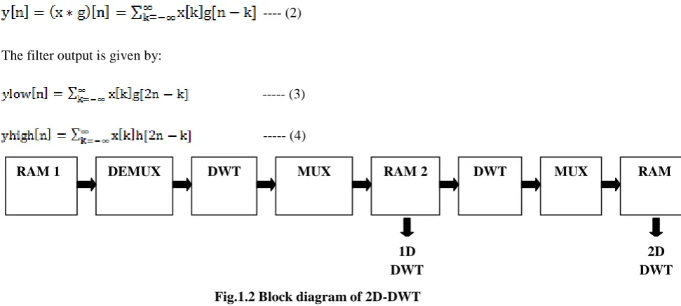
The DWT of signal x is calculated by passing it through a series filter. First the samples are passed through a
low pass filter with impulse response g resulting in a convolution of two:
---- (2)
The filter output is given by:
--- (3)
--- (4)
Fig.1.2 Block diagram of 2D-DWT
Suitable matlab command are used to get preprocessed input. Input image is converted to gray image of size
128*128.This pre processed input is given as contribution in Verilog HDL module. The input image is stored in
RAM which is controlled by input RAM 1 controller. This stored data is perused and given as input to demux
from this DWT module is figured with harr wavelet as transform. This initially iterated data is 1D yield, which
requires promote calculation of next ;eve; to accomplish 2D calculation.
This information exhibit in RAM 2 is accessible for second cycle. The information is additionally perused from
that point with the assistance of demux and facilitate it is send to DWT module for calculation and data is
written in RAM with the help of multiplexer to get 2D DWT. This 2D DWT output is stored as text file read
using matlab commands and demonstrate final output image i.e. 2D DWT transformed image. This transformed
image is approved on FPGA equipment utilizing Xilinx and again process it to matlab to observe output image
is whether 2D DWT or not.[2]
Fig.1.3 DWT System Block
RAM 1 DEMUX DWT MUX RAM 2 DWT MUX RAM
1D DWT
2D DWT
ADDER
SUBTRACTOR
RIGHT SHIFTER EVEN
ODD
Dout Average
Dout Subtract
132 | P a g e
Tree b (Imaginary Part)III. FPGA IMPLEMENTATION OF DUAL TREE COMPLEX WAVELET TRANSFORM
The use of complex wavelets in image processing was originally set up in 1995 by J.M. Lina and L. Gagnon in
the framework of the Daubechies orthogonal filters banks. The complex wavelet transform (CWT) is a
complex-valued extension to the standard discrete wavelet transform (DWT)Dual tree complex wavelet transform is
relatively recent enhancement to DWT with critical extra properties: It is nearly shift invariant and directionally
selective in two and higher dimensions. It achieves this with a redundancy factor of only 2d substantially lower
than the undecimated DWT[1]. The multidimensional dual tree CWT is nonseparable but is based on
computationally efficient, separable filter bank.
Making the wavelet responses analytic is a good way to halve their bandwidth and hence minimise aliasing. But
we cannot use complex filters in to obtain analyticity and perfect reconstruction together, because of conflicting
requirements[9]. Analytic filters must suppress negative frequencies, while perfect reconstruction requires a flat
overall frequency response. So we use the Dual Tree:-
• to create the real and imaginary parts of the analytic wavelets separately, using 2 trees of purely real filters; • to efficiently synthesise a multiscale shift-invariant filter bank, with perfect reconstruction and only 2:1
redundancy (and computation);
• to produce complex coefficients whose amplitude varies slowly and whose phase shift depends approximately
linearly on displacement[12]
Fig.1.4 Block Diagram of 2D-DTCWT
In dual tree complex wavelet transform input image is decomposed into 16 levels by two separable 2D-DWT
from which 12 are of high sub-bands and 4 are of low sub-bands [14]. As a result, sub bands of 2D DT-CWT at
each level are obtained as:
(LHa + LHb) /√2, (LHa – LHb) /√2, (HLa + HLb) /√2, (HLa – HLb) /√2, (HHa + HHb) /√2, (HHa – HHb) /√2
X
h0(1)
g0(1)
h1(1)
h0(2)
h1(2)
h0(3)
h1(3)
g
1(1)
g0(2)
g1(2)
g0(3)
g1(3)
2
2
2
2
2
2
2
2
x(n)
133 | P a g e
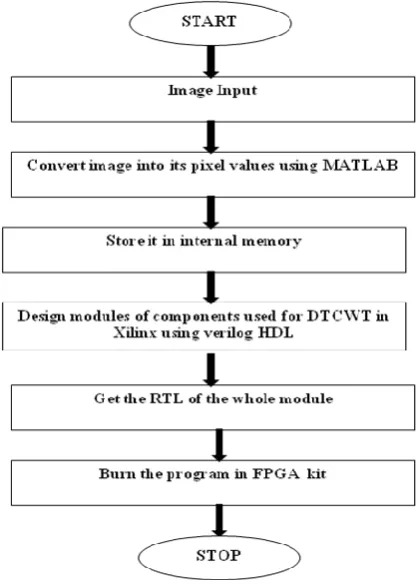
Above flow diagram shows the proposed methodology.
To begin with our aim we start our work with inputimage. The input image is processed into MATLAB with use of suitable commands to convert into its pixel
values. The data is stored in internal memory using a text file which contain input image pixel values in Verilog.
The design of DWT hardware use the concept of Harr transform because of simplicity and less hardware
requirement for its implementation. In this algorithm average the two pixel values and this average will give
average and difference component
.
Fig. 1.5 Flow Diagram of Proposed system
IV.CONCLUSION
This paper highlighted design of DWT and dual tree complex wavelet transform (DTCWT) architecture. The
computed system can be implemented in MATLAB and Verilog HDL, later on this result is validated on FPGA
Spartan 6. The pixel values of input image where operated using harr wavelet transform. The result portrayed us
that the proposed architecture provides better enhancement characteristics as compared to discrete wavelet
transform. In Future we endeavor to execute proposed design calculation utilizing even less assets, utilizing
diverse mother wavelet and analyse comes about on various equipment stage for accomplishing desired
134 | P a g e
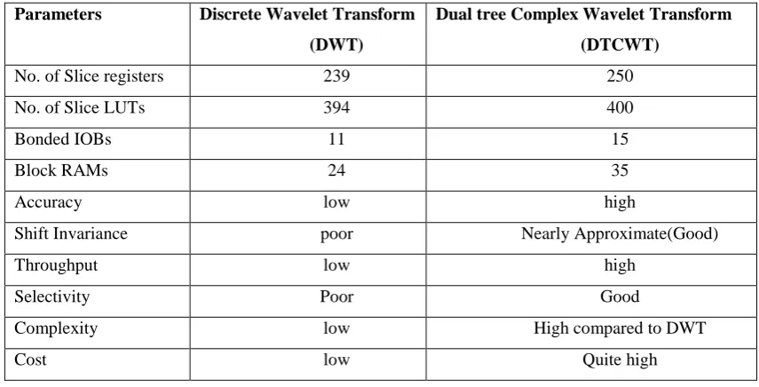
Table 1. Hardware Utilisation and characteristics Comparison
Table I. shows comparison between hardware utilization and Characteristics of Discrete Wavelet Transform and Dual
tree Complex Wavelet transform which concludes that DTCWT may uses more hardware but the quality of image and
performance will be better than that of DWT.
V. ACKNOWLEDGEMENT
First of all I articulate my deep appreciation and legal responsibility to my venture manual prof. Ravi Mishra
who became continually been an asset and director of motivation at some point of the assignment improvement
and execution in all issue of work.
REFERENCES
[1] SK Umar Faruk, Ramanaiah ―FPGA Implementation of Image Denoiser using Dual Tree Complex Wavelet Transform (DTCWT)‖ International Journal of Applied Engineering Research ISSN 0973-4562 Volume 12, November 14, 2017
[2] Guffran Kahan, Anil Sawant ―Spartan 6 FPGA Implementation Of 2d-Discrete Wavelet Transform In Verilog HDL‖IEEE International Conference on Advances in Electronics, Communication and Computer Technology
(ICAECCT), 2016
[3] Ferhat Canbay, Vecdi Emre levent ―An area efficient real time implementation of dual tree complex wavelet transform in field programmable gate arrays‖ IEEE International Conference on Bioinformatics and
Bioengineering, November 2015
[4] Prabhjot Kaur ―Image processing using discrete wavelet transform‖ IPASJ International Journal of Electronics
& Communication (IIJEC) Volume 3, Issue 1, January 2015
Parameters Discrete Wavelet Transform (DWT)
Dual tree Complex Wavelet Transform (DTCWT)
No. of Slice registers 239 250
No. of Slice LUTs 394 400
Bonded IOBs 11 15
Block RAMs 24 35
Accuracy low high
Shift Invariance poor Nearly Approximate(Good)
Throughput low high
Selectivity Poor Good
Complexity low High compared to DWT
135 | P a g e
[5] Ravi Mishra, Rohit Raj Singh ―Benefits of Dual tree complex wavelet transform over Discrete wavelettransform for image fusion‖ IJIRST–International Journal for Innovative Research in Science &
Technology,Volume1 Issue 11, April 2015
[6] S.Allin Christe, M.Balaji ―FPGA Implementation of 2D Wavelet Transform of Image Using Xilinx System Generator‖ International Journal of Applied Engineering Research, ISSN 0973-4562 Vol. 10 No.29, 2015
[7] V. Kumar, S.K. Gawre ―Power Quality Analysis Using Wavelet Transform: A Review‖ 2014 International
Conference on Innovations in Engineering and Technology (ICIET’14) Volume 3, Special Issue 3, March 2014
[8] Vineetha Soman ―FPGA Implementation of Discrete Wavelet Transform for Image Processing‖ IJSRD -
International Journal for Scientific Research & Development Vol. 2, Issue 01, 2014
[9] Nick Kingsbury ―Dual-Tree Complex Wavelets - their key properties and a range of image-processing applications‖ Signal Processing and Communications Laboratory Department of Engineering, University of
Cambridge, March 2013
[10] Jayavani Adabala, K. Naga Prakash ―Dual Tree Complex Wavelet Transform for Digital Watermarking‖
International Journal of Advances in Engineering & Technology, ISSN: 2231-1963, Sept 2012
[11] Chengjun Zang, Chunyan Wang ―A Pipeline VLSI Architecture for Fast Computation of the 2-D Discrete Wavelet Transform‖ IEEE transactions on circuits and systems—I: regular papers, vol. 59, no. 8, August 2012
[12] Nick Kingsbury ―Complex-valued Wavelets, the Dual Tree, and Hilbert Pairs‖ Signal Processing &
Communications Group, Dept. of Engineering, University of Cambridge, February 2012
[13] Iman A. El Shehaby, Trac D.Tran ―Implementation and application of local computation of wavelet coefficients in the dual-tree complex wavelets‖ International Conference of Image Processing, November 2009
[14] Guangming Shi ―An Efficient Folded Architecture for Lifting-Based Discrete Wavelet Transform” IEEE transactions on circuits and systems-II: express briefs, vol. 56, no. 4, April 2009
[15] Xiaodong Xu, Yiqi Zhou ―Efficient FPGA Implementation of 2-D DWT for 9/7 Float Wavelet Filter‖ IEEE