FINITE ELEMENT ANALYSIS ON LEAF SPRING
MADE OF COMPOSITE MATERIAL
Z. Triveni
1, B. Amara Babu
21
M.Tech., Student,
2Associate Professor,Dept of Mechanical Engineering, PBR VITS, Kavali
ABSTRACT
A leaf spring is a simple form of spring commonly used for the suspension in wheeled vehicles. Weight reduction can be achieved by designing new materials and sophisticated manufacturing processes. Due to increasing competition and innovation in recent decades, automobile industries show interest in replacing conventional steel leaf spring with fiber-reinforced composite leaf spring which has advantages such as higher strength to weight ratio, higher stiffness, high impact energy absorption, and lesser stresses. Objective of this project is to present a general study on the performance comparison of composite (Carbon fiber–reinforced polymer) leaf spring and conventional leaf spring by both Analytical and Finite Element Analysis. Leaf spring is modeled in ANSYS software. The conventional steel leaf spring and the composite leaf spring were analyzed under constant and variable load conditions using ANSYS software and analytical method and the results are compared .The conclusion of work is to minimize stress and deformation in carbon/epoxy composite leaf spring compared to steel leaf spring for automobile suspension system.
Keywords:
Composite, harmonic response analysis, Leaf Spring, modal analysis, static analysis.
I. INTRODUCTION
A spring is defined as an elastic body, whose function is to distort when loaded and to recover its original shape when the load is removed.[1]
Semi- elliptic leaf springs are almost universally used for suspension in light and heavy commercial vehicles. For cars also, these are widely used in rear suspension. The spring consists of a number of leaves called blades. The blades are varying in different lengths. The blades are usually given an initial curvature or cambered so that they will tend to straighten under the load. The leaf spring is based upon the theory of a beam of uniform strength. The lengthiest blade has eyes on its ends. This blade is called main or master leaf, the remaining blades are called graduated leaves. All the blades are bound together by means of steel straps.[2]
543 | P a g e
II. LITERATURE REVIEW
Many industrial visits, past recorded data shows that steel leaf springs are manufactured by EN45, EN45A,60Si7, EN47, 50Cr4V2, 55SiCr7 and 50CrMoCV4 etc. These materials are widely used for production of the parabolic leaf springs and conventional multi leaf springs. Leaf springs absorb the vehicle vibrations, shocks and bump loads (Induced due to road irregularities) by means of spring deflections, so that the potential energy is stored in the leaf spring and then relieved slowly [1]. Ability to store and absorb more amount of strain energy ensures the comfortable suspension system. Many suspension systems work on the same principle including conventional leaf springs. However, for the same load and shock absorbing performance, conventional (steel) leaf springs use excess of material making them considerably heavy. This can be improved by introducing composite materials in place of steel in the conventional spring. Studies and researches were carried out on the applications of the composite materials in leaf spring [1,2].A composite mono leaf spring with an integral eye was manufactured and tested for the static load conditions [2].Fatigue life prediction was also done by authors so as to ensure a reliable number of life cycles of a leaf spring. Further, a leaf spring had been modeled in conventional way and simulated for the kinematic and dynamic comparatives [3]. Cyclic creep and cyclic deformation was also studied [4]. Efforts were taken for Finite Element Analysis of multi leaf springs. These spring were simulated and analyzed by using ANSYS 7.1[5].Premature failure in leaf springs was also studied so as to suggest remedies on application of composite leaf springs. [6, 7, 8]
III. CONSTITUENTS OF FIBER REINFORCED COMPOSITES
In general, a composite is a material mixture created by a synthetic/natural assembly of two or more physically and chemically distinct components. The first component is a selected filler or reinforcing agent (discontinuous phase) whilst the other component is a compatible matrix binder (continuous phase). These two components are combined in order to achieve specific characteristics and properties. Different types of fibers matrix, and processing techniques are used for composite fabrication. [2]
3.1 Fiber
Fibers are the principal constituents in a fiber reinforced composite material. They occupy the largest volume fraction in a composite laminate and share the major portion of the load acting on a composite structure. Proper selection of the fiber type, fiber volume fraction, fiber length, and fiber orientation is very important. [2]
3.1.1 Glass fiber. Glass fibers are the most common of all reinforcing fibers for polymeric matrix composites
(PMC). The principal advantages of glass fibers are low cost, high tensile strength, high chemical resistance, and excellent insulating properties. [2]
3.1.2 Carbon fiber. Carbon fibers are commercially available with a variety of tensile modulus values ranging
from 207 GPa on the low side to 1035 GPa on the high side. In general, the low-modulus fibers have lower density, lower cost, higher tensile and compressive strengths, and higher tensile strains-to failure than the high-modulus fibers. [2]
3.2 Matrix
as unsaturated polyesters, epoxies and phenolics, and polypropylenes, polyethylenes and elastomers, respectively, are widely used for composite applications. [2]
3.3 Preparation of Composite
In the present investigation, a leaf spring made with carbon fiber reinforced polymer (CFRP) material is considered which has the major constituent’s carbon fiber and epoxy resin and made by hand layup method. In this analysis, the conventional steel leaf spring is tested for static load condition and results are compared with a virtual model of composite material leaf spring. Leaf spring is modeled in CATIAV5 software and it is imported and simulated in ANSYS 12.0 for better understanding. Results of composite leaf spring are compared on the basis of analysis reports produced by ANSYS software. The material used for conventional steel leaf spring is 55Si2Mn90 (BIS) and for composite leaf spring Carbon/Epoxy material is used.
IV. DEFINITON OF THE PROBLEM
The automobile industry is showing increased interest in the replacement of steel spring with carbon fiber composite leaf spring due to high strength to weight ratio. Therefore; this project aims at comparative study of design parameters of a traditional steel leaf spring assembly and mono composite leaf spring with bonded end joints. [1]
The aim of the present study is to conduct structural analysis on composite (Carbon fiber–reinforced polymer) leaf spring and conventional leaf spring by both Analytical and Finite Element Analysis. Leaf spring is modeled in ANSYS software. The conventional steel leaf spring and the composite leaf spring were analyzed under Constant and Variable Load conditions using ANSYS software and Analytical Method and the results are compared.
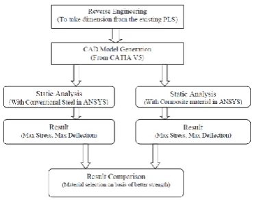
V. METHODOLOGY
In order to achieve objective of the present project, a flow chart is prepared which shows various steps involved in the analysis.
Figure 1 Flow chart to achieve the objective
5.1 Dimensions of leaf spring
545 | P a g e
Table1. Design Parameters of Leaf Spring
S. No Parameters Value
1 Total Length of the spring (Eye to Eye)
1540 mm
2 Free Camber (At no load condition)
136 mm
3 Thickness of leaf 13 mm
4 Width of leaf spring 70 mm
Figure2. The Leaf Spring used for the investigation
The Modeling of the mono leaf spring structure was done using CATIA V5 R17 software and the analysis was done using ANSYS software.
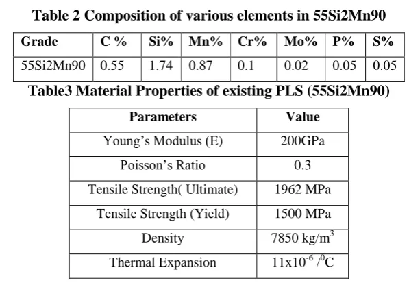
5.2 Material Properties of Steel Leaf Spring
The material composition and properties of steel leaf spring is given below [13]
Table 2 Composition of various elements in 55Si2Mn90
Grade C % Si% Mn% Cr% Mo% P% S%
55Si2Mn90 0.55 1.74 0.87 0.1 0.02 0.05 0.05
Table3 Material Properties of existing PLS (55Si2Mn90)
Parameters Value
Young’s Modulus (E) 200GPa
Poisson’s Ratio 0.3
Tensile Strength( Ultimate) 1962 MPa Tensile Strength (Yield) 1500 MPa
Density 7850 kg/m3
Thermal Expansion 11x10-6 /0C
5.3 Selection of composite material:
Table4 Material properties of Carbon fiber/E-poxy
PARAMETERS VALUE
Young’s Modulus (E) 105GPa
Poisson’s Ratio 0.1
Tensile Strength( Ultimate) 760 MPa Tensile Strength (Yield) 110 MPa
Density 1600kg/m3
Thermal Expansion 2.1x10⁻⁶ /0C
VI. PREPARATION OF PROJECT
The Modeling of the complete mono leaf spring structure was done using CATIA V5 R17 software and the analysis was done using ANSYS software.
6.1 CAD Modeling
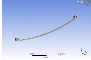
The CAD model of mono leaf spring used for analysis is shown in the fig 3.
Figure3 Model of Mono Leaf Spring
Figure4. 3-D Model of leaf spring
The model of leaf spring is imported into ANSYS 12.0, the boundary conditions and material properties are specified as for the standards according to the practical application. Fig4 shows the imported geometry of mono leaf spring.
Meshing is nothing but the descritization of object into the small parts called as the elements. The number of elements taken is 594 and the total number of nodes is 4686.
Fig 5 shows the meshed model of leaf spring.
547 | P a g e
VII. ANALYSIS
7.1 Analytical Calculation of Leaf Spring
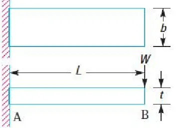
Leaf springs are made of flat plates. The advantage of leaf spring over helical spring is that the ends of the spring may be guided along a definite path as it deflects to act as a structural member in addition to energy absorbing device. [12]
As the leaf springs may carry shocks, lateral loads, brake torque, driving torque etc., they are to be designed carefully. Consider a single plate fixed at one end and loaded at the other end.
Figure 6. Flat Spring (Cantilever type)
Let t = Thickness of plate, b = Width of plate, and
L = Length of plate or distance of the load W from the cantilever end. We know that the maximum bending moment at the cantilever end A,
M=W.L……….. (1)
and section modulus,
Z=
=
= bt
2………(2)
Therefore, Bending stress in such a spring,
=
=
=
………(3)
We know that the maximum deflection for a cantilever with concentrated load at the free end is given by,
=
=
=
……….(4)
The values of deflection and Normal stresses by using the above formulae (3),(4) are calculated for the steel leaf spring subjected to different loads as shown in the table given below
Table5. The values of deflection and normal stress for different load conditions
Load
(N)
Normal stress
(MPa)
Deflection
(mm)
1000 195.26 28.71
2000 390.5 57.36
3000 587.75 86.04
4000 781 114.7
5000 976.25 143.4
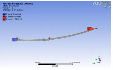
7.2 Loading & Boundary Conditions
For the leaf spring analysis left eye of the leaf spring is fixed to the chassis of the vehicle with the help of pin and right eye is allowed for displacement in the Y- direction and free to move in the X-direction
Figure7. Loading and Boundary Conditions of Leaf Spring
After providing the material to the model, meshing and loading as well as boundary condition now we have to solve the design space created for the two leaf spring models.
The comparison is based on the maximum normal stress generated and the value of maximum total deflection.
7.3 Deflection of Steel and composite leaf spring
Total Deflection is the value of deformation obtained when the spring is subjected to load. Here we applied central point load on the leaf spring. The Fig.8 &Fig 9shows the deflection of steel and composite leaf springs under the application of 1000N point load at the centre
Figure 8 Deformation of steel leaf spring Figure 9. Deformation of Composite leaf spring
549 | P a g e
7.4 Normal Stress for Steel and composite Leaf Spring
In general the stress is the resistance offered by the body for the applied loading. Normal stress is the resistance offered normal to the body, as the load is applied normal to the body.
Figure 10. Normal Stress for Steel leaf spring Figure 11. Normal Stress for Composite
leaf spring
VIII. RESULTS AND DISCUSSION
8.1 Comparison of Analytical and FEA results for Steel
The values of deflection under different load conditions for the steel leaf spring from analytical results and from finite element analysis are tabulated in Table 6.
Table 6. Comparison of Deflection results for steel leaf spring
Load (N) Deflection Variation
Analytical(mm) FEA(mm)
1000 28.71 25.84 9.1%
2000 57.36 51.38 10.42%
3000 86.04 77.52 9.9%
4000 114.7 103.36 9.8%
5000 143.4 129.2 9.7%
From the Table 6, it is observed that the maximum deflection was at a load of 4000N and the deflection is 114.7mm and by FEM, it is 103.36mm which is lesser than free camber of the leaf spring and it is observed that with the increase of load to 5000N, the conventional result shows that the spring may not be suitable for the given conditions.
The values of normal stress under different load conditions for the steel leaf spring from analytical results and from finite element analysis are tabulated in Table 7.
Table 7 Comparison of Normal Stress results for steel leaf spring
Load (N)
Normal stress Variation Analytical(Mpa) FEA(Mpa)
1000 195.26 172.71 11.54
2000 390.5 345.42 11.45%
3000 587.75 518.12 11.84%
4000 781 755.61 3.25%
From the Table 7, it is observed that the maximum deflection was at a load of 4000N and the deflection is 114.7mm and by FEM, it is 103.36mm which is lesser than free camber of the leaf spring and it is observed that with the increase of load to 5000N, the conventional result shows that the spring may not be suitable for the given conditions.
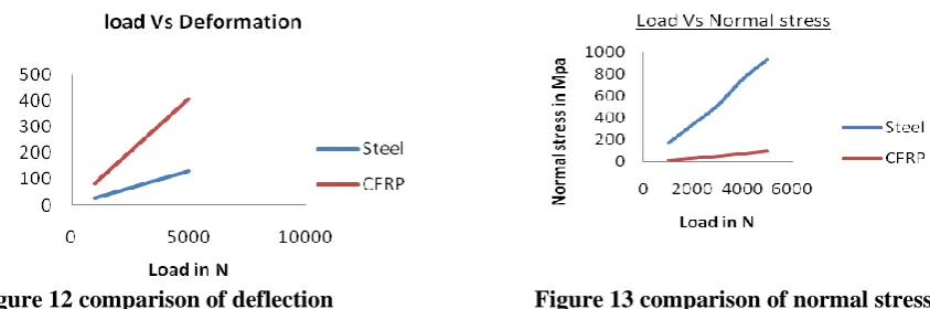
8.2 Comparison graph between two leaf springs
The variation of deformation with different load conditions for the steel and composite leaf spring is given in the Figure 12.
Figure 12 comparison of deflection
Figure 13 comparison of normal stress
From the fig 12 we observed that as the load increases the deflection also increased, and we observed the same results for both the springs but the CFRP leaf spring take the more deflection as compared with steel leaf spring at the same load conditions. As the stiffness of steel leaf spring is much larger than that of composite material as evident from the above graph.
From the fig 13, it is observed that more stresses are induced in the composite material compared with the steel leaf spring, because the material is not isotropic.
8.3 Modal analysis on leaf spring
Modal analysis is the procedure of determining a structure's dynamic characteristics; namely, resonant frequencies, damping values, and the associated pattern of structural deformation called mode shapes.
In the modal analysis we are going to fix the two eye ends of leaf spring. Here we will get the result as the different modes of frequencies;
Comparison of frequencies for both steel and composite leaf springs in Modal analysis
Table 8 Comparison of frequencies of both steel and composite leaf springs
Mode Frequency[Hz]
Steel leaf spring Composite leaf spring
1. 74.587 97.322
2. 130.74 170.78
3. 133.2 176.46
4. 243.52 317.71
5. 264.43 346.56
6. 368.95 489.46
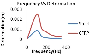
551 | P a g e From the figure 14 to 18 represents the variation of deformation for different frequencies at different loads both steel and composite leaf springs under harmonic response and it is observed that the composite material bears more fluctuations in loads.
Figure 14 the variation at a load of 1000N Figure 15 the variation of at a load of 2000N
Figure 16 the variation at a load of 3000N Figure 17 the variation at a load of 4000N
From the above graphs it is observed that the deformation of composite leaf spring is high at all the loads and it is particularly observed that the deformation is particularly high at 100 Hz frequency and then it is in a decreasing manner in both composite and steel leaf springs
IX. CONCLUSION
From the above investigation the following conclusions were made.
Static and dynamic analysis was done on both composite and steel leaf springs and the results were compared. After static analysis, modal analysis was performed to determine the frequency of leaf spring model.
After modal analysis, the harmonic analysis was done to determine the deformations at different frequencies under various loads. From the comparison, it was observed that the deflection in the composite is more but the bending stress induced in the carbon/epoxy composite leaf spring is less than the conventional steel leaf spring for the same load carrying capacity.
Stress and deformation in carbon/epoxy composite leaf spring compared to steel leaf spring for automobile suspension system were observed that for the same cross-section the composite material is not suitable for heavy loads due to high deflection, for heavy loads the cross section of composite has to be changed while using. It was observed that the composite leaf spring is lighter and more economical than the conventional steel spring with similar design specifications.
0 0.0005 0.001 0.0015
0 500
D
e
fo
rm
at
io
m
(m
)
frequency(Hz)
Steel
REFERENCES
Journal Papers:
[1] Senthil kumar and Vijayarangan, ―Analytical and Experimental studies on Fatigue life Prediction of steel leaf spring andcomposite leaf multi leaf spring for Light passanger veicles usinglife data analysis‖ ISSN 1392 1320 material science Vol. 13 No.2 2007.
[2] Shiva Shankar and Vijayarangan ―Mono Composite Leaf Spring for Light Weight Vehicle Design, End Joint, Analysis and Testing‖ ISSN 1392 Material Science Vol. 12, No.3, 2006.
[3] Niklas Philipson and Modelan AB ―Leaf spring modelling‖ ideon Science Park SE-22370 Lund, Sweden [4] Zhi’an Yang and et al ―Cyclic Creep and Cyclic Deformation of High-Strength Spring Steels and the
Evaluation of the Sag Effect:Part I. Cyclic Plastic Deformation Behavior‖ Material and Material Transaction A Vol 32A, July 2001—1697
[5] Muhammad Ashiqur Rahman and et al ―Inelastic deformations of stainless steel leaf springs-experiment and nonlinear analysis‖ Meccanica Springer Science Business Media B.V. 2009
[6] C.K. Clarke and G.E. Borowski ―Evaluation of Leaf Spring Failure‖ ASM International, Journal of Failure Analysis and Prevention, Vol5 (6) Pg. No.(54-63)
[7] J.J. Fuentes and et al ―Premature Fracture in Automobile Leaf Springs‖ Journal of Science Direct, Engineering Failure Analysis Vol. 16 (2009) Pg. No. 648-655.
[8] J.P. Hou and et al ―Evolution Of The Eye End Design Of A Composite Leaf Spring For Heavy Axle Load ‖ Journal of Science Direct, Composite Structures 78(2007) Pg. No. (351-358)
Books:
[9] Practical Finite Element Analysis by Nitin S. Gokhale [10] Composites – A Design Guide by Terry Richardson [11] ANSYS 10.0 Help for FEA Analysis
[12] Text book of Machine Design by R.S. Khurmi and J.K. Gupta
[13] Introduction to Steel Reference Books S. N. Bagchi and Kuldeep Prakash [14] Spring Designers Hand Book by Carlson