IMAGE ANALYSIS USING MORPHOLOGY
PROCESSING
Km. Shivani
Design Engineer, Associated Electronics Research Foundation Phase- II, Noida (India)
ABSTRACT
In the world of 6 billion people, biometric system has become indispensable to certain the genuine person.
Various methods have been implemented for inducting effective and efficient results. The main emphasis of this
paper is on the mathematical morphology developed by J. Serra and G. Mat heron. It is a set theory approach
to digital image processing based on finger prints. This research paper aims to find the right configuration of
morphology tools to obtain accurate results in many images. Our findings in this paper explain that how
repeated results obtained from multi images of same object extracts the results of desired accuracy.
Keywords
:
Minutiae, Feature Extraction, Minimally Connected, Skeletonization, Parasitic.
I. INTRODUCTION
While point and neighbourhood operations are generally designed to alter the look or appearance of an image for visual considerations, morphological operations are used to understand the structure or form of an image. This usually means identifying objects or boundaries within an image. Morphological operations play a key role in applications such as machine vision and automatic object detection. In an increasingly digital technology world, among the main innovation prospects and framework of future services like authentication that’s why the use of biometric based technology get developed. This is new and emerging technology due its high degree of maturity and reliability. Biometric system having two important utility 1) authentication or verification and 2) Identification in which person’s identity is verify by biometric sign (fingerprint, face, Pam, iris etc.). In a
recently published World Biometric Market Outlook (2005-2008), analysts predict that while the average annual growth rate of the global biometric market is more than 28%, by 2007. The technologies
(a) Ridge ending (b) Ridge bifurcation
Figure 1. Example of minutiae
II. BACKGROUND
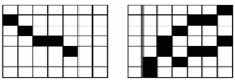
The feature extraction stage is concerned with the finding and measuring important similarities of the fingerprint that will be used to match it. And matching is the final goal of recognition system to findthe identity of the persons whose input fingerprint has been submitted i.e. it compares the extracted features or similarities from two fingerprints and determine the possibility that they have been captured from the same finger. Most of fingerprint recognition system is based on minutiae i.e. ridge ending and ridge bifurcation. Reliable minutiae extraction plays imperative role in recognition system Performance [2].There are two main approaches used to minutiae extraction. The first approach uses a thinned representation of the binary ridge structure, known as its skeleton. The second approach attempts to extract the minutiae locations from the grey-scale image itself. In view of that, there have been several approaches proposed for features not based on minutiae the cyclic structure of local fingerprint regions, shape signatures of fingerprint ridges and directional micro pattern histograms have been proposed as alternative fingerprint features. Wavelets, texture features and Gabor filters have also been investigated as tools for featureextraction [1]. Furthermore, experiments based on image verification and optical processing techniques have also been conducted. The most popular method for minutiae extraction is to use a binaries and skeletonised Representation of the fingerprint. The task is to extract the minutiae from the thinned ridge map; any black pixel that has only one black neighbour is a ridge endingsimilarly any black pixel with more than two black pixel neighbour is ridge bifurcation as shown in figure 2.
Figure 2.Ridge ending and ridge bifurcation in a thinned ridge map
segment image would be one an outer border of white pixels, the black pixels that form square, and a group of white pixels within the square [3]. We see that all pixels of a segment are directly adjacent to at least one other pixel of the same classification, they are all connected. Most morphological functions operate on 3 x 3 pixelneighbourhoods. The pixels in a neighbourhood are identified in one of two ways - sometimes interchangeably. The pixel of interest lies at the centre of the neighbourhood and is labelled X. The surrounding pixels are referred to as either X0 through X7, or by their compass coordinates E, NE, N, NW, W, SW, S, and SE. A pixel is four-connected if at least one of its neighbours in positions X0, X2, X4, or X6 (E, N, W, or S) is the same value [3]. The pixel is eight-connected if all neighbours are the same value. Under eight-connectivity, a set of pixels is said to be minimally connected if the loss of a single pixel causes the remaining pixels to lose connectivity.
Mathematical Morphological operations are used to extract image components that are Useful in the representation and description of region shape, such as
Boundaries extraction
Skeletons
Convex hull
Morphological filtering
Thinning
Pruning
Dilation
Erosion
For the next operations we consider a specific example. Suppose we have the following
2.1 Binary image and a structural element
2.2 Dilation
Image (B) expansion using structure element S
2.3 Erosion
When using erosion structural element also passes through all pixels of the image. If at a certain position every single pixel structuring element coincides with a single pixel binary image, thenthe logical disjunction of the central pixel structuring element with the corresponding pixel in the output image [4].
Image (B) erosion using structure element S
As a result of applying the erosion of all the objects smaller than the structural element will be erased, objects, connected by thin lines are disconnected and the sizes of all objects are reduced.
2.4 Boundaries Extraction
Morphological operations can also be used to distinguish the boundaries of binary object. This operation is very important, because the border is complete, and at the same time very compact description of the object. It is easy to see that the boundary points have at least one background pixel in its neighbourhood. Thus, applying the operator of erosion with a structural element that contains all possible neighbouring elements, we will remove all the boundary points. Then the boundary obtained by the operation of the difference between the sets of the original image and obtained as a result ofErosion [3].
Image after erosion Final Result
Thus, we are considered the basic operations of mathematical morphology, and several methods of their application. Hopefully, this material become useful to you in future endeavours.
2.5 Skeletons
The aim of the skeletonization is to extract a region-based shape feature representing the general form of an object.
2.6 Region Filling
After extracting boundary of images region has to be identified for medical purposes. Then to focus on particular area like tumours regions has to be filled to highlight that particular area [3].
(a) Set A (b)Complement of A(c) Structuring Element of B(d)Initial point inside the Boundary (e)-(h) Various Steps(i)Final Result union of (a) and (h)s Figure4: (a) Binary image(the white dot inside one of the regions is the starting point for the region-filling algorithm) (b) Result of filling that region (c) result of filling all regions.
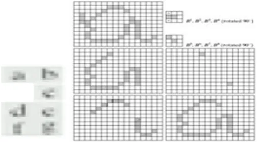
2.7 Convex Hull
A set A is said to be convex if the straight line segment joining any two points in A
Lies entirely within A.
Figure5
Figure5: (a) Structuring Elements(b)Set A (c)-(f) Results of convergence with the
Structuring elements shown in (a). (g)Convex Hull (h) Convex Hull showing the
Figure6: Result of limiting growth of convex hull algorithm to the maximum dimensions of the Original set of
points along the vertical and horizontal directions
2.8 Morphological Filtering
Structure Element Source Image:
2.9 Thinning
(a)
(b)
(c)
Figure 7: a) Original Image b) Binary Image c) Thinned Image
2.10 Pruning
The pruningalgorithm is a technique used in digital image processing based on mathematical morphology. It is used as a complement to the skeleton and thinning algorithms to remove unwanted parasitic components. In this case 'parasitic' components refer to branches of a line which are not key to the overall shape of the line and should be removed. These components can often be created by edge detection algorithms or digitization. The standard pruning algorithm will remove all branches shorter than a given number of points [2] [3]. The algorithm starts at the end points and recursively removes a given number (n) of points from each branch. After this step it will apply dilatation on the new end points with a (2N+1) (2N+1) structuring element of 1’s and will intersect the result with the original image. If a parasitic branch is shorter than four points and we run the algorithm with n = 4 the branch will be removed. The second step ensures that the main trunks of each line are not shortened by the procedure.
Figure 8: (a) Original image (b)and (c) Structuring elements used for deleting and points
(d)Result of three cycles of thinning (e) End points of (d), (f) Dilation of end points conditioned
On (a), (g) Pruned image.
III. CONCLUSION
REFERENCES
[1] Haralick, R. M., Sternberg, S. R. Zhuang, X, Image Analysis using MathematicalMorphology, IEEE Transactions on Pattern Analysis and Machine Intelligence, Ju., 9(4), str.,1987, 532-550.
[2] ShivprakashIyer, Sunil K. Sinha J., Automated condition assessment of buried sewerpipes based on digital imaging techniques. Indian Institute of Science, Sep.–Oct., 85, 2005,235–252.
[3] Jiang, X., Bunke, H., Edge Detection in Range Images Based on Scan LineApproximation,Computer Vision and Image Understanding, Vol. 73, No. 2, February, 1999, 183–199.
[4] Rodehorst, V., 1997. Architectural Image Segmentation Using Digital Watersheds. 7th Int. Conf. on Computer Analysis of Images and Patterns CAIP'97, Kiel, Germany, Sep. 10-12.