Compact Single-Layer Balanced Eighth-Mode Substrate Integrated
Waveguide Bandpass Filter with High Selectivity
Xiao-Bang Ji1, Qing Liu2, *, and Mi Yang3
Abstract—This letter proposes a compact single-layer balanced bandpass filter (BPF), which is realized by a new arrangement of eighth-mode substrate integrated waveguide (EMSIW) cavities. Under differential-mode (DM) operation, the half bisection topology of the proposed EMSIW filter can be equivalent to a quadruplet scheme based on four coupled EMSIW cavities. The negative cross coupling can be easily realized by the nature of the fringe electric fields of opened ends of EMSIW cavities. For the demonstration, a balanced EMSIW filter with the operating frequency at 2.4 GHz is designed, fabricated, and measured.
1. INTRODUCTION
Recently, balanced/differential filtering circuits have attracted substantial attention because of their excellent performances in terms of the immunity of environmental noises and interferences compared with single-end counterparts [1–4]. Furthermore, balanced bandpass filters (BPFs) using substrate integrated waveguide (SIW) technique have been studied due to their advantages of low loss, high power-handling capability, and low cost [5–7]. In [5, 6], balanced SIW filters are proposed and designed by using traditional full-mode SIW cavities, but their sizes are large. Balanced SIW filters with compact size and high selectivity are required in modern wireless communications. To reduce the size, dual-mode SIW and half-mode SIW (HMSIW) cavities are exploited to design balanced filters [7–10]. However, their sizes are still large. In [11], the authors proposed a new method to design compact balanced filters based on quarter-mode SIW (QMSIW) and eighth-mode SIW (EMSIW) cavities. The designed filters have compact sizes for size-reduced QMSIW/EMSIW cavities. However, the first designed balanced SIW filter in [11] has poor selectivity because no transmission zero (TZ) is close to the differential-mode (DM) passband. The second designed balanced SIW filter has good selectivity due to the quasi-elliptic response [11]. However, it has two substrate layers with special apertures to produce TZs, which increases the processing cost. Because the overall size of EMSIW cavity can be reduced by a factor of more than 7/8 compared to the conventional full-mode SIW cavity [11], the EMSIW cavity can be further exploited to design compact balanced BPF with high performance.
The primary motivation of this letter is to design a single-layer balanced EMSIW BPF, which can provide high selectivity, compact size, and good stopband performances of DM and common mode (CM) responses. For this purpose, EMSIW cavities with cross-coupling paths are adopted. The negative cross couplings are realized by the nature of coupled open ends of EMSIW cavities. Under the DM operation, half model of the proposed balanced EMSIW filter can be modeled by a quadruplet scheme. For the demonstration, a quasi-elliptic DM response EMSIW filter with the center frequency (f0d) of 2.4 GHz
and bandwidth of 340 MHz is designed, fabricated, and measured to verify the proposed structure. Measured results agree well with the simulated ones.
Received 15 July 2019, Accepted 10 September 2019, Scheduled 27 October 2019
* Corresponding author: Qing Liu ([email protected]).
2. THE PROPOSED EMSIW BALANCED BPF
The layout of the proposed balanced EMSIW BPF is shown in Fig. 1. The substrate material cer-10 with its relative permittivity of 10.2 and thickness of 0.787 mm is used for the design. The proposed BPF consists of one isosceles right-angled triangular patch (IRAT) resonator and six EMSIW cavities. The filter is symmetrical with respect to the symmetrical plane denoted by a dotted line in Fig. 1. A pair of balanced input ports is located at the hypotenuse of the IRAT resonator. A pair of balanced output ports is located at the opened right-angle opened side of EMSIW cavities. The frequency of the proposed filter is decided by the resonant frequency of the EMSIW cavity, which can be approximately calculated [11]:
f = √
2π·c
2π·L· √εrμr (1)
where μr and εr are the relative permeability and relative permittivity of the substrate; c is the speed of light in free space; andL is the equivalent width of the corresponding original square SIW cavity.
L2
X Y
W0
Port 2
g1
g5
X Symmetrica
Port 1
L1
L3
g4
l Plane Port 1'
g3
g2
Din
Port 2'
Figure 1. Layout of the proposed balanced filter using EMSIW cavities (black circle: metallic vias; orange: metallic layer; gray: substrate layer).
The electric-field distribution of the fundamental mode of EMSIW cavity is shown in Fig. 2(a). The electric-field distribution of the resonance mode of IRAT patch resonator is shown in Fig. 2(b), which can be considered by two back-to-back EMSIW cavities with removing the equivalent metal wall. Moreover, the electric fields on the locations of the two balanced input ports are out of phase, which means that the patch resonator can be excited by the differential signal and cannot be excited by the common signal. Thus, under DM operation, the proposed balanced structure provides a perfect electric conductor (PEC) along the symmetrical plane. Under CM operation, the effects of two in-phase input signals are canceled with each other, thereby failing to excite the resonance mode of the IRAT patch resonator in Fig. 2(b).
M
M Max
Min
(a) (b)
Figure 2. Electric-field distributions with resonances of 2.4 GHz on (a) the EMSIW cavity, (b) the IRAT Patch resonator.
M
M ax
in
P2 P1 P1' P2'
Max
Min
P2 P1 P1' P2'
(a) (b)
Figure 3. Simulated electric-field distributions inside the proposed balanced BPF at the center frequency. (a) DM operation, (b) CM operation.
R3 R4
P2
R1
R2
P1
R4'
R3' R2'
P1' P2' P2
3 4
-P1
1
2
-+
(a) (b)
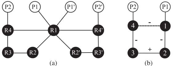
Figure 4. Coupling scheme of the proposed balanced EMSIW BPF. (a) Original four-port circuit, (b) half bisection under DM operation.
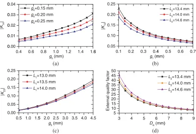
mode of IRAT patch resonator in Fig. 2(b) cannot be excited to pass energy to the adjacent EMSIW cavities, and the CM signal is fully attenuated with no visible electric field in the six EMSIW cavities. The coupling scheme of the proposed balanced EMSIW filter is shown in Fig. 4(a). Due to the symmetrical property of the proposed structure, a PEC will appear along the symmetrical plane under DM operation. As a result, the half bisection topology can be modeled by a classical quadruplet scheme, as shown in Fig. 4(b). The negative sign of cross-coupling path 1-4 is achieved by the fringe electric fields of opened ends of EMSIW cavities with small cuts. The cross-coupling strength M14 can be controlled by the parameters of g4 and g5. As shown in Fig. 5(a), the extracted cross-coupling coefficient |K14| against g4 and g5 is presented. When |K14| is increased (i.e., increasing g5 or decreasing g4), the two TZs will be near the passband because the filter can be equivalent to a quadruplet coupling scheme [12]. Thus, the two TZs can be controlled by parametersg4 andg5. The signs of main coupling paths 1-2 and 3-4 are also negative due to the fringe electric fields of opened hypotenuse sides of EMSIW cavities. The internal couplingsM12andM34can be controlled by parameters ofg1andg2, respectively. Because of the symmetry of the structure,g1 is equivalent tog2 (i.e.,M12=M34). As shown in Fig. 5(b), the extracted main coupling coefficient |K12|against g1 is presented. When g1 is decreased, the main coupling|K12| is decreased. The sign of main coupling M23 is positive, and it is realized by quasi-inductive window between two adjacent EMSIW cavities. As shown in Fig. 5(c), the extracted main coupling coefficient |K23|againstg3 is presented. Tapped lines with the terminating impedanceZ0= 50 Ω are used to feed the input and output (IO) resonators. Locations of two pairs of IO feeding lines are deviated from the equivalent electric walls to control the external quality factor (Qe), and the distance is denoted byDin.
The extracted Qe againstDin is shown in Fig. 5(d).
3. SIMULATED AND MEASURED RESULTS
Based on the proposed balanced structure in Fig. 1, a quasi-elliptic DM response EMSIW filter with a center frequency of 2.4 GHz and bandwidth of 340 MHz is designed for the demonstration. Two simulated transmission zeros are located at 2 and 2.77 GHz. The structure parameters of the proposed filter are: W0 = 0.59, g1 = 0.26, g2 = 0.25, g3 = 2.85, g4 = 0.22, g5 = 1.16, L1 = 13.59, L2 = 14.09,
0 0 0 0 0 | K14 | 0. 0. 0. 0. 0. 0. | K23 | 0.4 0.6 0.00 0.01 0.02 0.03 0.04
g4=0
g4=0
g4=0
0.5 1.0 1.5 .00 .05 .10 .15 .20 .25
L1=
L1=
L1=
0.8 1.0
g5(mm) 0.15 mm 0.20 mm 0.25 mm
5 2.0 2.5 3.0
g3(mm) =13.0 mm =13.5 mm =14.0 mm
1.2 1.4 1.6
3.5 4.0 4.5 6 External quality factor 0.1 0 0.05 0.10 0.15 0.20 0.25 | K12 | 3 4 5 10 15 20 25 30 35 40 45 50 External quality facto r
.2 0.3 0.4
g1(m
5 6
Din(mm)
4 0.5 0.6
mm)
L2=13.4 m
L2=14.0 m
L2=14.6 m
7 8 9
)
L2=13.4 mm
L2=14.0 mm
L2=14.6 mm 0.7 mm mm mm (a) (b) (c) (d)
Figure 5. Extracted external quality factor and coupling coefficients at operating frequency of 2.4 GHz. (a) Cross coupling |K14|, (b) main coupling |K12|, and (c) main coupling |K23|, (d) external quality factor.
To verify the proposed design, the prototype is fabricated. The circuit size is about 54.5 mm×15 mm (0.98λg×0.27λg), whereλg is the guided wavelength in the dielectric at 2.4 GHz. Measurement is carried
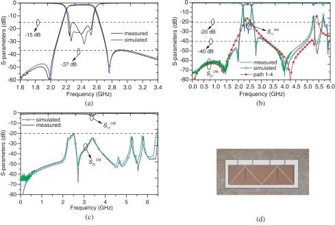
out on the Agilent N5244A network analyzer. The comparisons between the simulated and measured responses of the designed balanced BPF are presented in Fig. 6. Fig. 6(a) shows the DM responses of interested frequency band. The measuredf0d, insert loss (IL), minimum return loss (RL), and bandwidth
are 2.39 GHz, 1.65 dB, 15.29 dB, and 315 MHz (13.2%), respectively. Two TZs at 1.98 and 2.76 GHz can be clearly observed as expected. This means that the proposed balanced BPF realizes a high selectivity property. The measured wideband DM responses with simulated responses are shown in Fig. 6(b). Two additional TZs (1.41 and 4.03 GHz) are also observed, which may produce the surface wave providing a parasitic source-to-load coupling. When the internal EMSIW cavities (R2, R2’, R3 and R3’) are removed with maintaining the cavities of R1, R1’, R4, and R4’, the simulated DM response (red line with solid circles) is also shown in Fig. 6(b). Two simulated TZs at 1.35 and 4.26 GHz are also obtained to verify the parasitic source-to-load coupling. Good performance of out-of-band rejection is achieved. The measured upper stopband with rejection larger than 20 dB is up to 5.22 GHz (2.18f0d). Fig. 6(c)
shows the CM responses, and there is a 20.83 dB CM suppression level in the passband. Moreover, stopband of rejective level over 20 dB is obtained from 0 to 6.44 GHz (2.69f0d), which indicates that
the proposed filter has wideband CM suppression. A photograph of the fabricated filter is shown in Fig. 6(d).
1.6 1.8 2.0 2.2 2.4 2.6 2.8 3.0 3.2 3.4 -60
-50 -40 -30 -20 -10 0
-37 dB
S-parameters (dB)
Frequency (GHz)
measured simulated -15 dB
0.0 0.5 1.0 1.5 2.0 2.5 3.0 3.5 4.0 4.5 5.0 5.5 6.0 -80
-70 -60 -50 -40 -30 -20 -10 0
S-parameters (dB)
Frequency (GHz)
simulated path 1-4
S11DM
S21 DM -20 dB
-40 dB
measured
0 1 2 3 4 5 6
-80 -70 -60 -50 -40 -30 -20 -10 0
S-parameters (dB)
Frequency (GHz) simulated
S11CM
S21CM
measured
(a) (b)
(c) (d)
Figure 6. Measured and simulated frequency response of the proposed balanced BPF. (a) Passband of DM responses, (b) wideband of DM operation, (c) wideband of CM operation, (d) photograph of the fabricated filter.
Table 1. Compared with other reported balanced filters using SIW technique.
Ref. f0d
(GHz) m n
FBW (%)
IL (dB)
Size (λg×λg)
Upper stopbands (S21DM <−20dB
/S21CM <−20dB)
Q0
[1] 13.45 4 2 3.3 2.15 2.8×1.9 1.44f0d/1.32f0d 240
[2] 10.1 4 2 4.45 2.26 1.91×0.99 1.48f0d/1.6f0d 205
[3]-I 10 4 2 3 1.4 2.22×1.79 - 317
[3]-II* 10 4 2 2.5 - 1.14×1.08 - /
[6] 4.65 3 1 12 2.2 1.12×0.68 - 49
[7]-I 3.09 3 0 15.5 1.28 0.71×0.71 2.01f0d/1.69f0d 65
[7]-II* 3.09 4 2 15.2 1.34 0.79×0.37 2.56f0d/2.26f0d 89
This work 2.4 4 4 13.2 1.65 0.98×0.27 2.18f0d/2.69f0d 100
4. CONCLUSION
In this letter, a single-layer quasi-elliptic DM response BPF using EMSIW cavities is proposed. For the demonstration, a quasi-elliptic response EMSIW filter is designed, fabricated, and measured. Both the simulated and measured results indicate that the proposed balanced EMSIW BPF can simultaneously realize the merits of compact size, high selectivity, wideband of DM, and CM suppressions.
REFERENCES
1. Wei, F., P. Qin, Y. J. Guo, C. Ding, and X. W. Shi, “Compact balanced dual- and tri-band bpfs based on coupled complementary split-ring resonators (C-CSRR),”IEEE Microwave and Wireless Components Letters, Vol. 26, No. 2, 107–109, 2016.
2. Wei, F., Y. J. Guo, P. Qin, and X. W. Shi, “Compact balanced dual- and tri-band bandpass filters based on stub loaded resonators,” IEEE Microwave and Wireless Components Letters, Vol. 25, No. 2, 76–78, 2015.
3. Yang, Z.-J., Y.-Y. Shan, X.-T Zou, F. Wei, and B. Li, “A balanced bandpass filter with ultra-wide stopband and common-mode suppression,”Progress In Electromagnetics Research Letters, Vol. 77, 123–128, 2018.
4. Deng, K. and Z. Chen, “Wideband balanced filters with wideband common mode suppression using coupled lines,” Progress In Electromagnetics Research Letters, Vol. 65, 49–55, 2017.
5. Xu, X., J. Wang, and L. Zhu, “A new approach to design differential-mode bandpass filters on SIW structure,” IEEE Microwave and Wireless Components Letters, Vol. 23, No. 12, 635–637, 2013. 6. Chu, P., W. Hong, K. Wang, et al., “Balanced substrate integrated waveguide filter,” IEEE
Transactions on Microwave Theory and Techniques, Vol. 62, No. 4, 824–831, 2014.
7. Chu, H., P. Li, and J. Chen, “Balanced substrate integrated waveguide bandpass filter with high selectivity and common-mode suppression,” IET Microw., Antennas Propag., Vol. 9, No. 2, 133– 141, 2015.
8. Chu, P. and K. Wu, “Balanced dual-mode SIW filter,” Electron. Lett., Vol. 55, No. 4, 208–210, 2019.
9. Li, P., H. Chu, D. Zhao, and R. S. Chen, “Compact dual-band balanced SIW bandpass filter with improved common-mode suppression,”IEEE Microwave and Wireless Components Letters, Vol. 27, No. 4, 347–349, 2017.
10. Ho, M. and C. Li, “Novel balanced bandpass filters using substrate integrated half-mode waveguide,” IEEE Microwave and Wireless Components Letters, Vol. 23, No. 2, 78–80, 2013. 11. Li, P., H. Chu, and R. Chen, “Design of compact bandpass filters using quarter-mode and
eighth-mode SIW cavities,” IEEE Trans. Compon., Packag., Manuf. Technol., Vol. 7, No. 6, 956–963, 2017.