Electronic Thesis and Dissertation Repository
4-22-2016 12:00 AM
Analysis and Design Procedure for Liquid-Filled Conical Tanks
Analysis and Design Procedure for Liquid-Filled Conical Tanks
Under Seismic Loading
Under Seismic Loading
Ahmed Musa
The University of Western Ontario
Supervisor
Ashraf El Damatty
The University of Western Ontario
Graduate Program in Civil and Environmental Engineering
A thesis submitted in partial fulfillment of the requirements for the degree in Doctor of Philosophy
© Ahmed Musa 2016
Follow this and additional works at: https://ir.lib.uwo.ca/etd
Part of the Structural Engineering Commons
Recommended Citation Recommended Citation
Musa, Ahmed, "Analysis and Design Procedure for Liquid-Filled Conical Tanks Under Seismic Loading" (2016). Electronic Thesis and Dissertation Repository. 3724.
https://ir.lib.uwo.ca/etd/3724
This Dissertation/Thesis is brought to you for free and open access by Scholarship@Western. It has been accepted for inclusion in Electronic Thesis and Dissertation Repository by an authorized administrator of
Abstract
Steel conical tanks are widely used for liquid storage in North America and elsewhere. A number of those tanks collapsed in the last decades as a result of instability of the steel shells. Despite being widely used, no specific design procedure is available for conical tanks under dynamic conditions. The research conducted in the current thesis presents a simplified approach for the design of steel conical tanks when subjected to ground excitations in the form of horizontal and vertical excitations.
First, the capacity of steel conical tanks to avoid yielding and buckling of the tank vessel under hydrodynamic pressure resulting from horizontal ground excitation is evaluated using non-linear static pushover analysis. The capacity of steel conical tanks under hydrodynamic pressure resulting from vertical ground excitation is then evaluated using the same procedure. The analyses are conducted numerically using a non-linear finite element model that accounts for the effects of large deformations and geometric imperfections on the stability of steel conical tanks. Based on the obtained capacities, a design approach is proposed which is based on satisfying an interaction formula that avoids both yielding and buckling of the tank vessel. This formula is a function of the steel conical tank capacities and the seismic demands resulting from hydrodynamic pressure including both impulsive and sloshing components. Finally, this design approach is validated through comparison with the results of non-linear dynamic analysis.
The effect of the base rocking motion on the seismic behaviour of conical shaped steel tanks is then studied and a mechanical analog that simulates the forces acting on a conical tank subjected to a horizontal excitation including the effect of this base rocking motion is developed. This mechanical model takes the flexibility of the tank walls into consideration as well the hydrodynamic pressure acting on the tank base.
Keywords
Co-Authorship Statement
This thesis has been prepared in accordance with the regulations for an Integrated Article format thesis stipulated by the School of Graduate and Postdoctoral Studies at the University of Western Ontario. Statements regarding the co-authorship of individual chapters are as follows:
Chapter 2: CAPACITY OF LIQUID STEEL CONICAL TANKS UNDER HYDRODYNAMIC PRESSURE DUE TO HORIZONTAL GROUND EXCITATIONS
All the numerical work was conducted by A. Musa under close supervision of Dr. A. A. El Damatty. Drafts of Chapter 2 were written by A. Musa and modifications were done under supervision of Dr. A. A. El Damatty. A paper co-authored by A. Musa and A. A. El Damatty is published in Thin-walled structures journal.
Chapter 3: CAPACITY OF LIQUID-FILLED STEEL CONICAL TANKS UNDER VERTICAL EXCITATION
All the numerical work was conducted by A. Musa under close supervision of Dr. A. A. El Damatty. Drafts of Chapter 3 were written by A. Musa and modifications were done under supervision of Dr. A. A. El Damatty. A paper co-authored by A. Musa and A. A. El Damatty is published in Thin-walled structures journal.
Chapter 4: DESIGN PROCEDURE FOR LIQUID STORAGE STEEL CONICAL TANKS UNDER SEISMIC LOADING
Chapter 5: EFFECT OF BASE ROCKING MOTION ON THE SEISMIC BEHAVIOUR OF CONICAL SHAPED STEEL LIQUID STORAGE TANKS
To my beloved parents Musa Azab and Sanaa El Gendy
To my brother Sherief
To my sisters Noha, Shereen, and Maha
For their support and encouragement
To my supervisor, Dr. Ashraf A. El Damatty
Acknowledgments
I am eager to take this opportunity to thank everyone who helped me during my work in this research, made this thesis possible and an unforgettable experience for me
First, I would like to express my deepest sense of gratitude and appreciation to my supervisor Dr. Ashraf El Damatty for all his support, guidance, patience, and for all the knowledge he gave to me throughout the course of this thesis. I thank him for the great effort he put into training me in the scientific field. It was a great privilege to work with him.
I would also like to thank my former and current fellow graduate students, Dr. Haitham Aboshosha, Dr. Ahmed Hamada, Dr. Mahmoud Siddiqui, Ryan Jacklin , Tareq Ezabi, Mike Jolie, Amal Kamel, Mohamed Hamada, Carolina Santos, Adnan ElNajjar, Ahmed Elshaer, Joshua Rosenkrantz , Ahmed Alaadin, Fouad Yehia, Ibrahim Ibrahim, Mohamed Dawoud, Dr. Aiham Adawi, Dr. Ahmed Fahmy, Dr. Nedal Mohamed, Dr. Ahmed Dyasti, Dr. Ahmed Taha, Dr. Ahmed Alnuaim, Ahmed Suleiman, Osama Derby, Abdullah El Tawati, Maged Boshana , Hayder Al-Maamori , Mahmoud Halwagy, Papia Sultana , Ahmed Mniena, Emad Abraik, Jesus Gonzalez, Mahmoud Kassem, Mohamed Abdel Salam, Mohamed Ali, Saud Al Fayez, Yazeed Alsharedah, Ahmed Abu Hussein, Mohamed Gamal, Abdel Rhaman Fouad, and Mohamed Askar.
A special thanks to Dr. Ahmed Elansary for his support and friendship. It was a pleasure to go through my undergraduate and postgraduate studies long and enjoyable journey with you. Another special thanks goes to one of my best friends Ahmed Mansour for his support and giving me many precious memories.
Dr. Osama Elhawary, Mohamed Abusharkh, Fabio Sammarco, and Andrea Liguori. Moreover, I would like to express my sincerest thanks to all my friends overseas in Egypt for their encouragement, belief in me and for their good spirit.
I take this opportunity to express the profound gratitude from my deep heart to my beloved parents and my siblings, the most precious people in my life, for their love and continuous support they have provided me throughout my life. I also would like to thank my cousins Mostafa, Ahmed, Maged, and Omar for their encouragement.
Table of Contents
Abstract ... ii
Co-Authorship Statement... iii
Acknowledgments... ii
Table of Contents ... iv
List of Tables ... viii
List of Figures ... ix
List of Appendices ... xvii
Chapter 1 ... 1
1 Introduction ... 1
1.1 General ... 1
1.2 Background ... 3
1.3 Literature Review... 5
1.3.1 Conical Tanks under Hydrostatic Pressure ... 5
1.3.2 Liquid Tanks under Seismic Loading ... 7
1.4 Objectives of Thesis ... 12
1.5 Scope of Thesis ... 12
1.5.1 Chapter 2 – Capacity of Liquid Steel Conical Tanks under Hydrodynamic Pressure Due To Horizontal Ground Excitation ... 13
1.5.2 Chapter 3 – Capacity of Liquid-Filled Steel Conical Tanks under Vertical Excitation ... 13
1.5.3 Chapter 4 – Design Procedure for Liquid Storage Steel Conical Tanks under Seismic Loading ... 14
1.5.4 Chapter 5 – Effect of Base Rocking Motion on the Seismic Behaviour of Conical Shaped Steel Liquid Storage Tanks ... 14
Chapter 2 ... 19
2 Capacity of Liquid Steel Conical Tanks under Hydrodynamic Pressure Due To Horizontal Ground Excitation ... 19
2.1 Introduction ... 19
2.2 Hydrodynamic Pressure ... 26
2.3 Finite Element Model ... 29
2.4 Method of Analysis ... 30
2.5 Impulsive Base Shear Capacity ... 33
2.5.1 Perfect Tanks ... 33
2.5.2 Imperfect Tanks ... 36
2.6 Sloshing Base Shear Capacity ... 42
2.7 Base Shear Seismic Demand ... 44
2.8 Conclusions ... 49
2.9 References ... 51
Appendix A ... 54
Chapter 3 ... 63
3 Capacity of Liquid-Filled Steel Conical Tanks under Vertical Excitation ... 63
3.1 Introduction ... 63
3.2 Hydrodynamic Pressure ... 70
3.3 Finite Element Model ... 72
3.4 Method of Analysis ... 73
3.5 Results of Analysis ... 74
3.5.1 Deformed Shape... 74
3.5.2 Vertical Force Capacity ... 75
3.6 Effect of Geometric Imperfection ... 79
3.8 Conclusions ... 89
3.9 References ... 91
Appendix B ... 95
Chapter 4 ... 100
4 Design Procedure for Liquid Storage Steel Conical Tanks under Seismic Loading . 100 4.1 Introduction ... 100
4.2 Hydrodynamic Forces ... 106
4.2.1 Horizontal Excitation ... 106
4.2.2 Vertical Excitation ... 107
4.3 Geometric Imperfections ... 109
4.4 Steel Conical Tank Capacities ... 111
4.4.1 Horizontal Excitation ... 111
4.4.2 Vertical Excitation ... 112
4.5 Proposed Design Procedure ... 112
4.6 Time-History Analysis ... 113
4.7 Results of Time History Analysis ... 117
4.8 Proposed Design Approach Validation ... 124
4.9 Summary of the Design Approach ... 126
4.10Conclusions ... 127
4.11References ... 128
Appendix C ... 132
Chapter 5 ... 141
5 Effect of Base Rocking Motion on the Seismic Behaviour of Conical Shaped Steel Liquid Storage Tanks ... 141
5.3 Finite Element Model ... 151
5.4 Fluid-Added Matrix Validation ... 152
5.5 Effect of Base Rocking Motion ... 154
5.5.1 Free Vibration Analysis ... 155
5.5.2 Non-Linear Dynamic Analysis ... 158
5.6 Mechanical Model for Steel Conical Tanks Undergoing Rocking ... 161
5.7 Numerical Example ... 169
5.8 Conclusions ... 171
5.9 References ... 172
Chapter 6 ... 176
6 Conclusions and Recommendations ... 176
6.1 Summary ... 176
6.2 Conclusions ... 177
6.3 Recommendation for Future Work ... 179
Appendix D ... 180
List of Tables
Table 2-1 Seismic hazard design values for selected locations in terms of (g) ... 46
Table 3-1 Seismic hazard design values for selected locations in terms of (g) ... 85
Table 4-1 Selected ground excitation records corresponding to different seismic zones 115
Table 5-1 Practical RC shaft dimensions and corresponding rotational stiffness Kαα .. 155
Table 5-2 % reduction range in the natural frequency (f1) of the cosθ impulsive mode 157
Table 5-3 Upper and lower bounds for % change in Vmaxfor different seismic zones... 160
List of Figures
Fig. 1-1 (a) Pure conical tank, (b) Combined conical tank ... 2
Fig. 2-1 (a) Pure conical tank, (b) Combined conical tank ... 20
Fig. 2-2 Stresses induced due to inclination of the wall ... 21
Fig. 2-3 Co-ordinate system for the steel conical tank and dimensional parameters ... 27
Fig. 2-4 Distribution of different pressure modes: (a) Circumferential distribution, (b) Vertical distribution for impulsive pressure modes n=1, 3, 5, .. , (c) Vertical distribution for impulsive pressure modes n=2, 4, 6, .., (d) Vertical distribution for fundamental sloshing pressure mode ... 28
Fig. 2-5 (a) Coordinates and degrees of freedom for a consistent shell element, (b)Finite element mesh for half cone ... 29
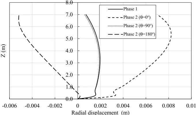
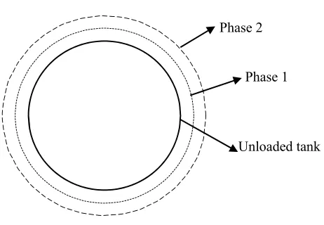
Fig. 2-6 Radial deformations of the tank walls at the end of each phase ... 32
Fig. 2-7 Deformed shape at the end of each phase of loading ... 32
Fig. 2-8 Variation of impulsive base shear ratio with the tank height and thickness ... 34
Fig. 2-9 Variation of impulsive base shear ratio with the tank radius and thickness ... 34
Fig. 2-10 Variation of impulsive base shear ratio with the tank angle of inclination and thickness ... 35
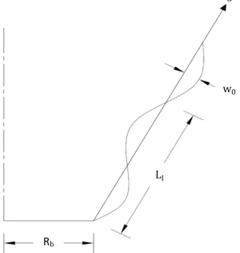
Fig. 2-11 Assumed imperfection shape along the generator of tank ... 36
Fig. 2-12 Variation of radial displacements with height for the case of hydrodynamic pressure only ... 38
Fig. 2-13 Deformed shape at failure for the case of hydrodynamic pressure only ... 39
Fig. 2-15 Comparison of impulsive base shear capacity for different imperfection levels
and actual base shear values for the three seismic zones (θv=30) ... 40
Fig. 2-16 Comparison of impulsive base shear capacity for different imperfection levels and actual base shear values for the three seismic zones (θv=45) ... 40
Fig. 2-17 Comparison of impulsive base shear capacity for different imperfection levels and actual base shear values for the three seismic zones (θv=60) ... 41
Fig. 2-18 Comparison of sloshing base shear capacity for different imperfection levels and actual base shear values for the three seismic zones (θv=30) ... 43
Fig. 2-19 Comparison of sloshing base shear capacity for different imperfection levels and actual base shear values for the three seismic zones (θv=45) ... 43
Fig. 2-20 Comparison of sloshing base shear capacity for different imperfection levels and actual base shear values for the three seismic zones (θv=60) ... 44
Fig. 2-21 Schematic presentation of the equivalent mechanical analog (El Damatty and Sweedan 2006) ... 46
Fig. 2-22 Variation of ratio VIRb/Wh with h/Rb for perfect tanks (θv =30) ... 54
Fig. 2-23 Variation of ratio VIRb/Wh with h/Rb for perfect tanks (θv=45) ... 54
Fig. 2-24 Variation of ratio VIRb/Wh with h/Rb for perfect tanks (θv=60) ... 55
Fig. 2-25 Variation of ratio VIRb/Wh with h/Rb for good tanks (θv=30) ... 55
Fig. 2-26 Variation of ratio VIRb/Wh with h/Rb for good tanks (θv=45) ... 56
Fig. 2-27 Variation of ratio VIRb/Wh with h/Rb for good tanks (θv=60) ... 56
Fig. 2-28 Variation of ratio VIRb/Wh with h/Rb for poor tanks (θv=30) ... 57
Fig. 2-30 Variation of ratio VIRb/Wh with h/Rb for poor tanks (θv=60) ... 58
Fig. 2-31 Variation of ratio VSRb/Wh with h/Rb for perfect tanks (θv=30) ... 58
Fig. 2-32 Variation of ratio VSRb/Wh with h/Rb for perfect tanks (θv=45) ... 59
Fig. 2-33 Variation of ratio VSRb/Wh with h/Rb for perfect tanks (θv=60) ... 59
Fig. 2-34 Variation of ratio VSRb/Wh with h/Rb for good tanks (θv=30) ... 60
Fig. 2-35 Variation of ratio VSRb/Wh with h/Rb for good tanks (θv=45) ... 60
Fig. 2-36 Variation of ratio VSRb/Wh with h/Rb for good tanks (θv=60) ... 61
Fig. 2-37 Variation of ratio VSRb/Wh with h/Rb for poor tanks (θv=30) ... 61
Fig. 2-38 Variation of ratio VSRb/Wh with h/Rb for poor tanks (θv=45) ... 62
Fig. 2-39 Variation of ratio VSRb/Wh with h/Rb for poor tanks (θv=60) ... 62
Fig. 3-1 Combined steel conical tank ... 64
Fig. 3-2 Stresses induced due to inclination of the wall ... 69
Fig. 3-3 Co-ordinate system for the steel conical tank and dimensional parameters ... 71
Fig. 3-4 Different vertical axisymmetric pressure modes ... 72
Fig. 3-5 Coordinates and degrees of freedom for a consistent shell element, (b)Finite element mesh for half cone ... 73
Fig. 3-6 Radial deformations of the tank walls at the end of each phase of loading (R=4.0m, h=7.0m, θv=45o) ... 75
Fig. 3-7 Deformed shape at the end of each phase of loading ... 75
Fig. 3-9 Variation of total vertical force ratio with the tank radius and thickness (h=7.0m,
θv=45o) ... 77
Fig. 3-10 Variation of total vertical force ratio with the tank angle of inclination and thickness (Rb=5.0m, h=7.0m) ... 78
Fig. 3-11 Assumed imperfection shape along the generator of tank ... 80
Fig. 3-12Effect of level of geometric imperfection on the total vertical force capacity (θv=30) ... 82
Fig. 3-13 Effect of level of geometric imperfection on the total vertical force capacity (θv=45) ... 82
Fig. 3-14 Effect of level of geometric imperfection on the total vertical force capacity (θv=60) ... 83
Fig. 3-15 Schematic presentation of the equivalent mechanical model, (Sweedan and El Damatty (2005)) ... 84
Fig. 3-16 Simplified V/H response spectral ratio, (Bozorgnia and Campbell (2004)) ... 86
Fig. 3-17 Comparison of total vertical force capacity to the vertical force demand for the three seismic zones (θv=30) ... 87
Fig. 3-18 Comparison of total vertical force capacity to the vertical force demand for the three seismic zones (θv=45) ... 88
Fig. 3-19 Comparison of total vertical force capacity to the vertical force demand for the three seismic zones (θv=60) ... 88
Fig. 3-20 Variation of ratio Nh/WcRb with h/Rb for perfect tanks (θv=30) ... 95
Fig. 3-21 Variation of ratio Nh/WcRb with h/Rb for good tanks (θv=30) ... 95
Fig. 3-23 Variation of ratio Nh/WcRb with h/Rb for perfect tanks (θv=45) ... 96
Fig. 3-24 Variation of ratio Nh/WcRb with h/Rb for good tanks (θv=45) ... 97
Fig. 3-25 Variation of ratio Nh/WcRb with h/Rb for poor tanks (θv=45) ... 97
Fig. 3-26 Variation of ratio Nh/WcRb with h/Rb for perfect tanks (θv=60) ... 98
Fig. 3-27 Variation of ratio Nh/WcRb with h/Rb for good tanks (θv=60) ... 98
Fig. 3-28 Variation of ratio Nh/WcRb with h/Rb for poor tanks (θv=60) ... 99
Fig. 4-1 (a) Pure conical tank, (b) Combined conical tank ... 101
Fig. 4-2 Stresses induced due to inclination of the wall ... 102
Fig. 4-3 Effect of horizontal acceleration on a conical tank ... 106
Fig. 4-4 Equivalent mechanical model for conical tanks subjected to horizontal excitation, (El Damatty and Sweedan (2006)) ... 107
Fig. 4-5 Effect of vertical acceleration on a conical tank ... 108
Fig. 4-6 Equivalent mechanical model for conical tanks subjected to vertical excitation Sweedan and El Damatty (2005) ... 109
Fig. 4-7 Assumed imperfection shape along the generator of tank ... 110
Fig. 4-8 Schematic for the scaling of the ground motion spectrum to match the NBCC 2010 spectrum ... 116
Fig. 4-9 (a) Coordinates and degrees of freedom for the consistent shell element (Koizey and Mirza (1997)), (b)Finite element mesh for half cone ... 117
Fig. 4-11 Hydrodynamic pressure distribution for a steel conical tank (Rb=4m, h=5m)
subjected to Northridge-01; (a) Horizontal Impulsive Pressure, (b) Horizontal Sloshing
Pressure, and (c) Vertical Impulsive Pressure ... 121
Fig. 4-12 Displaced shape for steel conical tank (Rb=4m, h=5m, θv=45o) subjected to Northridge-01; (a) Horizontal displacement, (b) Vertical displacement, and (c) Transversal displacement ... 122
Fig. 4-13 Required thickness relative to ts for the cases PE-30, PE-45, TOR-PE-60, TOR-GD-30, TOR-GD-45, TOR-GD-60, 30, 45, MON-PE-60, MON-GD-30 ... 132
Fig. 4-14 Required thickness relative to ts for the case TOR-PR-30 ... 132
Fig. 4-15 Required thickness relative to ts for the case MON-PR-30 ... 133
Fig. 4-16 Required thickness relative to ts for the case VAN-PE-30 ... 133
Fig. 4-17 Required thickness relative to ts for the case VAN-GD-30 ... 134
Fig. 4-18 Required thickness relative to ts for the case VAN-PR-30 ... 134
Fig. 4-19 Required thickness relative to ts for the case TOR-PR-45 ... 135
Fig. 4-20 Required thickness relative to ts for the case MON-GD-45 ... 135
Fig. 4-21 Required thickness relative to ts for the case MON-PR-45 ... 136
Fig. 4-22 Required thickness relative to ts for the case VAN-PE-45 ... 136
Fig. 4-23 Required thickness relative to ts for the case VAN-GD-45 ... 137
Fig. 4-24 Required thickness relative to ts for the case VAN-PR-45 ... 137
Fig. 4-25 Required thickness relative to ts for the case TOR-PR-60 ... 138
Fig. 4-27 Required thickness relative to ts for the case MON-PR-60 ... 139
Fig. 4-28 Required thickness relative to ts for the case VAN-PE-60 ... 139
Fig. 4-29 Required thickness relative to ts for the case VAN-GD-60 ... 140
Fig. 4-30 Required thickness relative to ts for the case VAN-PR-60 ... 140
Fig. 5-1 (a) Pure conical tank, (b) Combined conical tank ... 142
Fig. 5-2 Co-ordinate system for the steel conical tank and dimensional parameters ... 146
Fig. 5-3 Circumferential distribution different pressure modes ... 147
Fig. 5-4 (a) Coordinates and degrees of freedom for a consistent shell element, (b)Finite element mesh for half cone ... 152
Fig. 5-5 Base shear force time history for a steel conical tank subjected to a horizontal excitation using two finite element meshes ... 152
Fig. 5-6 Time history for V/W for cases of rocking allowed and prevented ... 153
Fig. 5-7 Time history for M/WRb for cases of rocking allowed and prevented ... 153
Fig. 5-8 (a) Elevated tank structure, (b) RC shaft cross-section, (c) Springs simulating the RC shaft, and (d) RC shaft stiffness matrix ... 155
Fig. 5-9 Variation of the parameter (f1Rb(ρs/E)0.5) with the slenderness ratio h/Rb ... 157
Fig. 5-10 Artificial ground excitation for Toronto seismic zone with the corresponding spectrum ... 159
Fig. 5-11 Schematic presentation of the equivalent mechanical model ... 162
Fig. 5-12 Variation of (f1Rb(ρs/E)0.5) with slenderness ratio h/Rb for different θv ... 163
Fig. 5-14 Comparison between the proposed mechanical model parameters and the values
provided by (Haroun and Ellaithy 1985a) ... 166
Fig. 5-15 Variation of the parameter mr/mt with ratio h/Rb ... 167
Fig. 5-16 Variation of the parameter mf/mt with the slenderness ratio h/Rb ... 167
Fig. 5-17 Variation of the parameters hrb/h and hr/h with the slenderness ratio h/Rb ... 167
Fig. 5-18 Variation of the parameter hfb/h and hf/h with the slenderness ratio h/Rb ... 168
List of Appendices
Appendix A ... 54
Appendix B ... 95
Appendix C ... 132
Chapter 1
1
Introduction
1.1 General
Liquid storage tanks are widely used around the world for the purpose of storing different kinds of liquids. The contained liquid might be water used for drinking and fire protection or any other fluid used in a specific industry. There are two types of liquid storage tanks depending on the required pressure head: either a ground tank, or an elevated tank supported on a steel framing system or a concrete shaft. The tank vessel is commonly constructed of either steel or reinforced concrete. The choice of the tank, whether ground or elevated, and the construction material is mainly based on the function of such tank in addition to the properties of the contained liquid. Steel tanks have the advantage of being faster in construction time and lighter in weight compared with their reinforced concrete counterparts.
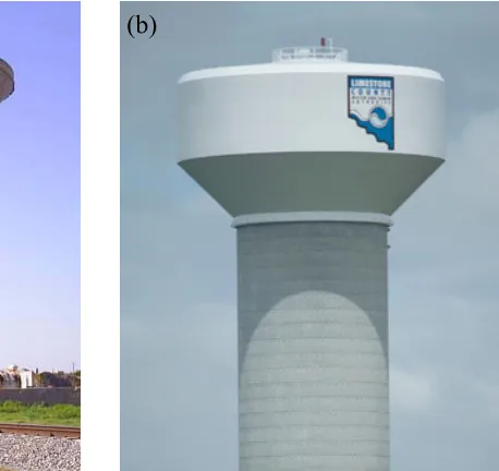
Tanks are found in a variety of cross sectional shapes such as: cylindrical, rectangular, and conically-shaped which is the focus of the current study. A conical tank might consist of a pure truncated cone as shown in Fig. 1-1a or might be capped with a cylindrical part and is referred to in this case as combined conical tank as shown in Fig. 1-1b. Although such tanks whether pure or combined are commonly constructed, no specific design procedure is found for conical tanks in most liquid-tanks specifications. The only guidelines are based on treating a conical-shaped tank as a cylindrical tank with equivalent height, radius, and thickness.
stresses σm in this region. Tensile hoop stresses σh are also induced circumferentially
through the tank shells.
Fig. 1-1 (a) Pure conical tank1, (b) Combined conical tank2
A conical tank in static conditions has to support its own weight in addition to the applied hydrostatic pressure acting on the tank walls and base. For steel conical tanks, the hydrostatic pressure will be more critical than the weight of the tank due to the relatively light weight of steel structures. For the case of liquid-storage conical tanks under dynamic loads, the behaviour is more complicated than other ordinary structures. This is due to the presence of the contained liquid, which vibrates with different dynamic (vibration) characteristics than those of the tank walls.
For a liquid-filled conical tank subjected to an earthquake excitation, the walls, the floor, and the contained liquid are subjected to acceleration. As a result, the walls are affected by the inertial forces of the wall in addition to the hydrodynamic pressure of the contained liquid. The contained liquid can be divided into two parts: the first part is mainly the lower
1http://forums.auran.com/trainz/showthread.php?17876-FEC-Key-West-extension-modern-day/page7 2http://www.caldwellwatertanks.com
amount of liquid, which moves with the walls of the tank and is called the impulsive liquid mass. The second part is mainly the upper amount of liquid and is called the convective liquid mass, which undergoes sloshing due to vibration. The ratio of the convective mass to the impulsive one increases as the tank becomes shallower. Also, the frequency of the impulsive vibration modes is much higher than those of the convective vibration mode.
1.2 Background
Dynamic behaviour of Liquid storage tanks is so important to understand as any failure to such structures might have a serious consequences in addition to the structure damage; for example, losing water supply or release of combustible materials stored inside. In 1964, Alaska earthquake caused damage to a lot of liquid storage tanks highlighting the need for revising the design guidelines found by that time. A lot of studies have been performed regarding the behaviour of liquid tanks, especially cylindrically-shaped, when subjected to earthquake excitations. One of the main findings was the importance of including the tank walls’ flexibility when analyzing a liquid tank under seismic action, especially for the case of steel tanks due to the relatively small wall thickness, instead of assuming rigid walls. The vertical component for an earthquake excitation was also found to be important to include when analyzing a liquid tank as vertical acceleration is transmitted to a horizontal hydrodynamic loading acting on a tank wall. As a result, tensile hoop stresses are amplified and might lead to inelastic buckling of the shell.
The equivalent mechanical model was then introduced as a simplified approach to analyze liquid tanks subjected to earthquake excitations. The idea was to replace the contained fluid with a set of lumped masses and linear springs that mimic the total base forces obtained from dynamic analysis. The base forces are the base shear and overturning moment for the case of horizontal excitation and total vertical force for the case of vertical excitation.
seismic design guidelines for conical tanks found in some specifications are based on using an equivalent cylinder.
The state of stresses under hydrostatic pressure for the case of cylindrical tanks is not similar to the case of conical tanks due to the inclination of the tank walls resulting in high compressive meridional stresses near the tank base in addition to tensile hoop stresses. For the case of horizontal seismic excitation, the induced hydrodynamic pressure will amplify both meridional and hoop stresses at one side of the tank and reduce them at the other side based on the direction of the ground acceleration, while the induced hydrodynamic pressure due to vertical excitation will amplify or reduce the induced stresses in an axisymmetric manner based on the direction of the ground acceleration, i.e., upwards or downwards.
A set of experimental and numerical studies have been carried out on steel conical tanks under both hydrostatic and hydrodynamic pressure in order to investigate the effect of wall inclination on the tank behaviour and state of stresses. For the seismic-related studies, the majority of them focused on calculating the base forces that are transmitted to the supporting structure due to a seismic event using equivalent mechanical models, while none of them addressed the conical tank’s resistance when subjected to either horizontal or vertical ground excitation. This tank resistance is required to assess the vessel wall thickness to insure its adequacy to resist the applied hydrodynamic pressure due to a seismic event.
In the previous studies for steel conical tanks under horizontal ground excitations, the supporting structure in the form of steel framing system or reinforced concrete shaft was assumed to be rigid regarding rotational motions, i.e., no tank base rocking is allowed. For the case of a flexible supporting system, the rocking base motion is expected to change the vibration characteristics of the tank-support system and, consequently, the induced hydrodynamic forces.
These capacities are then used to provide a simplified design procedure to design steel conical tanks subjected to earthquake excitations. The effect of allowing base rocking motion on seismic behaviour of steel conical tanks is also studied and a mechanical model is provided for such case.
1.3 Literature
Review
1.3.1
Conical Tanks under Hydrostatic Pressure
As for most building structures, the motivations for performing detailed investigations are usually related to total or partial failures. The first study related to steel conical tanks was conducted by Vandepitte et al. (1982) after the collapse of a conical steel water tower in Belgium. In this study, a large number of small-scale conical tank models were tested experimentally under hydrostatic pressure. The models were gradually filled with water till buckling occurred. The test results were used to develop a set of design curves for different base restraining conditions. The effect of geometric imperfections on the safety factor of the conical tanks was also studied. In 1990, a steel conical water tower collapsed in Fredericton, Canada when it was filled with water for the first time. Vandepitte (1999) concluded that the main cause of failure was related to the inadequate thickness of the tank walls at the base. This was due to the designer’s underestimation of the amplitude of the geometric imperfections as their design was based on results obtained from the field of aerospace where a superior quality control takes place.
Hafeez et al. (2010) investigated the buckling behavior of combined conical tanks under the effect of hydrostatic pressure. The study was conducted numerically using a three-dimensional finite element model. The effects of geometric imperfection and residual stresses as well as the variation of the geometric and material parameters on the buckling capacity of combined conical tanks were also investigated. Finally, a comparison between the buckling capacities of combined and equivalent pure conical tanks was conducted. It was concluded that the concept of equivalent pure cones underestimate the buckling capacity and the yield load of the combined cones.
Several attempts have been made to provide a simplified design procedure for steel conical tanks under hydrostatic pressure suitable for everyday use by practicing engineers. El Damatty et al. (1999) developed a simple design approach for steel conical tanks with a load factor value of 1.4 taking into account geometric imperfections, snow and roof loads, and the existence of an upper cylindrical cap. The idea was to avoid the yielding state of tanks, which was shown to always precedes buckling for the tank at any point. An economic design approach was also proposed by reducing the tank wall thickness as height increases. This study was limited to conical tanks with vertical inclination angle of 45o.
Sweedan and El Damatty (2009) extended the latter study of combined conical tanks under hydrostatic loading using regression analysis based on the results of large number of analyzed tanks. This large database included a variation of tank dimensions, angle of inclination of the wall, cylindrical cap ratio, yield strength values, and geometric imperfection level.
El Ansary et al. (2010) provided a powerful numerical tool that couples a non-linear finite element model and a genetic algorithm optimization technique for the analysis and design of steel conical tanks under hydrostatic pressure. This numerical tool is capable of selecting the set of design variables which satisfies the structure safety requirements while achieving a minimum structure weight and cost.
at the tank base simulating the case of retrofitting an existing tank, while the second is pinned to the base representing the case of a newly designed tank. It was concluded that, the addition of extra free stiffeners increases the limit loads of the tanks by 35% to 64%, while for the case of pinned stiffeners this increase varies between 71% and 136%.
1.3.2
Liquid Tanks under Seismic Loading
1.3.2.1 Horizontal
Excitation
The first studies regarding seismic behaviour of cylindrical liquid tanks were based on the assumption that the tank walls are rigid, i.e., the flexibility of the tank walls has no effect on the contained fluid vibrations (Jacobsen (1949), Housner (1957), and Housner (1963)). This notion was considered valid until the earthquake in Alaska in the year 1964 where considerable damage occurred to a large number of cylindrical liquid storage tanks in the form of roof damage, wall buckling, and total collapse (Hanson (1968)).
More studies were carried out after earthquake in Alaska in an attempt to accurately interpret the vibration characteristics, taking into consideration the effect of the wall flexibility where the tank deformations affect the hydrodynamic pressure, i.e., fluid-structure interaction takes place. It was concluded that the flexibility of cylindrical tank walls amplifies the tank’s response. Therefore, it has to be accounted for (Veletsos (1974), and Haroun and Housner (1981,1982)).
induces membrane compressive circumferential stresses causing buckling to the tankshell. The elastic buckling at the top represented the critical state for the medium and tall models, while plasticity was reached at the shell before buckling for the shallow tank. The slenderness ratio was found to have some influence on the critical PGA with no clear trend.
Virella et al. (2008) proposed a nonlinear static procedure based on the capacity spectrum method found in ATC-40 in order to evaluate the elastic buckling of above-ground anchored steel tanks due to horizontal seismic excitations. The objective was to obtain the minimum peak ground acceleration (PGA) value that produces buckling in the tank shell. The obtained critical PGA estimates were then compared with those calculated using the dynamic buckling analyses performed in the latter study. The following was concluded: (a) the nonlinear static procedure resulted in slightly smaller, i.e., conservative, values for the critical PGA compared to the dynamic buckling results, (b) similar first buckling modes were observed by using both static and dynamic buckling analyses, (c) the critical PGA decreases with the slenderness ratio.
Djermane et al. (2014) attempted to evaluate the current design guidelines related to dynamic instability provided by AWWA-D100 and EC8 provisions for cylindrical steel tanks using a numerical shell finite element model. The idea was to evaluate the critical PGA values that cause the tank instability and then compare with their counterparts obtained by the codes’ provisions. The authors concluded the following: (a) comparison for broad tanks showed a good agreement between numerical and EC8 results, (b) standards need some revisions in order to provide improved consideration of the imperfections and geometric nonlinearities for the case of tall tanks, (c) simple stress limitation found in the standards is very conservative.
the hydrostatic pressure reduces the periods for shell-type vibration modes, but it does not affect cantilever-type vibration modes, (b) the secondary buckling is an elastic buckling mode, but it is strongly influenced by the occurrence of plasticity in other parts of the structure.
El Damatty et al. (1997b,c) conducted the first study to assess the behavior of conical tanks under seismic loading where a coupled shell element-boundary element formulation was developed to simulate the fluid-structure interaction. A fluid added mass matrix was derived and added to the mass matrix of the structure to be incorporated into a nonlinear dynamic analysis routine. The results showed that some of the tanks suffered dynamic instability although they were designed with factor of safety of about 2.5 under hydrostatic pressure. This in turn reflects the importance of the seismic loading compared to the hydrostatic one.
As the finite element dynamic analysis for the tank-fluid system is considered computationally expensive, researchers tried to find a simpler procedure to estimate the total forces acting on the liquid tank structure when subjected to an earthquake event. A practical alternative was to model the contained liquid as lumped masses attached to the tank wall rigidly or through linear springs instead of modelling the contained fluid as a continuum, which in turn reduce the computation cost for the tank-fluid dynamic analysis. The masses-springs system is called equivalent mechanical model whose main objective is to match the resulting forces and moments obtained using dynamic analysis.
Moslemi et al. (2011) analyzed an elevated steel conical tank twice when subjected to El-Centro ground motion; once using finite element analysis where the fluid was modeled using displacement-based elements and once using the ACI procedure which is based on Housner’s mechanical model for equivalent cylindrical tank. The difference between the two methods in terms of base shear and base moment was around 6%.
1.3.2.2 Vertical
Excitation
Regarding the vertical component, Marchaj (1979) attributed the failure of metallic tanks during past earthquakes to the lack of consideration of vertical acceleration in their design. Veletsos and Kumar (1984) studied the effect of wall flexibility on the response of cylindrical tanks when subjected to vertical component of ground shaking. It was concluded that the hydrodynamic effects for a flexible tank might be substantially larger than those induced in a rigid tank of the same dimensions, and for an intense excitation, they might be of the same order of magnitude as the hydrostatic effects.
The latter study considered only the radial motion of the tank walls and neglected the effect of axial deformations. This assumption was validated by Haroun and Tayel (1985a) who provided an analytical method for the computation of the dynamic characteristics in terms of natural frequencies, corresponding mode shapes and stress distributions for partly filled cylindrical tanks subjected to vertical excitations. Results were compared to numerical solution where the liquid region was treated analytically and the elastic shell was modeled by finite elements (Haroun and Tayel (1985b)) and both methods showed excellent agreement.
Haroun and Tayel (1985) analyzed some cylindrical liquid storage tanks under simultaneous horizontal and vertical excitations numerically using finite element method. The goal of the study was to assess the relative importance of inclusion of the vertical component of the earthquake in the behaviour of the cylindrical tanks. The axial stresses resulting from the vertical component was found to be much lower compared to those induced due to the horizontal component of the earthquake due to overturning moment. However, the hoop stresses due to vertical component was higher than those due to horizontal component which might lead to the yielding of the steel shell increasing the probability of buckling of the tank walls near the base of the tank.
Haroun and Abou-Izzeddine (1992) performed a parametric study in order to evaluate the effects of different factors that influence the seismic response of an elastic cylindrical tank supported on a rigid base when subjected to a vertical excitation by considering shell-liquid-soil interaction. It was concluded that foundation soil-tank interaction reduces the tank response in general, and this reduction is a function of the soil shear-wave velocity as well as tank geometric properties.
El Damatty et al. (1997b,c) derived a fluid-added mass matrix for both horizontal and vertical ground motions to be incorporated in time history analysis and it was shown how the contribution of vertical excitation to the dynamic instability is important. This coupled shell element-boundary element model was verified experimentally using shaking table testing for scaled conical shell aluminum models (Sweedan and El Damatty (2002), El Damatty et al. (2005), and El Damatty et al. (2005)).
the importance of vertical excitation consideration. Also, meridional wall stresses at the extreme inner fibre at the tank base are shown to be higher than those developing at the mid-surface due to bending effects associated with the boundary conditions at the tank base.
1.4 Objectives
of
Thesis
The major objectives of the thesis can be summarized in the following:
1- Estimate the capacity of steel conical tanks under hydrodynamic pressure due to horizontal ground excitations using nonlinear static analysis for both perfect and imperfect conical tanks.
2- Estimate the capacity of steel conical tanks under hydrodynamic pressure due to vertical ground excitations using nonlinear static analysis for both perfect and imperfect conical tanks.
3- Provide a simplified seismic design procedure for steel conical tanks when subjected to both horizontal and vertical ground excitations and validating this procedure using dynamic analysis.
4- Study the effect of the base rocking motion on the seismic behaviour of steel conical tanks
5- Develop an equivalent mechanical model for steel conical tanks taking the base rocking motion into consideration.
1.5 Scope
of
Thesis
1.5.1
Chapter 2 – Capacity of Liquid Steel Conical Tanks under
Hydrodynamic Pressure Due To Horizontal Ground Excitation
In this chapter, the capacity of liquid steel conical tanks when subjected to hydrodynamic pressure resulting from horizontal ground excitation is obtained. In order to achieve that, a numerical finite element model is used based on static pushover analysis. The capacity is expressed in terms of the resulting total base shear at failure for the two components of the hydrodynamic pressure; impulsive and sloshing. As the impulsive and sloshing vibration modes are well-separated regarding their natural frequencies, the analyses are done separately for each pressure component. Base shear capacities for perfect steel conical tanks are presented in the form of charts for different dimensions, walls’ thicknesses, and angles of inclination. As geometric imperfections play an important role in defining the capacity of shell structures, the effect of the geometric imperfections on the capacity of steel conical tanks is then studied and similar charts are provided for the case of imperfect tanks. On the other side, the seismic demands in the form of total base shear are obtained using equivalent mechanical model found in the literature for both impulsive and sloshing vibration modes and compared to the obtained capacities in order to assess the design of the steel conical tanks. Three seismic zones are considered in this comparison representing moderate to high seismic zones in Canada.
1.5.2
Chapter 3 – Capacity of Liquid-Filled Steel Conical Tanks
under Vertical Excitation
is used to convert the horizontal response spectra for the same three seismic zones considered in the previous chapter to vertical spectra.
1.5.3 Chapter 4 – Design Procedure for Liquid Storage Steel
Conical Tanks under Seismic Loading
In this chapter, a simplified design procedure is proposed to design steel conical liquid tanks subjected to horizontal and vertical components of ground excitations. The approach is based on satisfying a design equation which is function of the steel conical tank capacities and seismic demands. The steel conical tank capacities are those obtained in the previous two chapters using non-linear static analyses for both horizontal and vertical excitations, while the seismic demands are obtained using equivalent mechanical models found in the literature. This design approach takes into consideration the effect of geometric imperfections and the effect of sloshing hydrodynamic pressure. In order to validate this design procedure, non-linear time history analyses are conducted and their outcomes are compared with those of the proposed design procedure in terms of the minimum wall thickness. The time history analyses are conducted based on 11 natural earthquake records scaled to different seismic zones in Canada. The selection of the ground motions is based on a procedure where the seismic hazard is deaggregated in terms of the distance and magnitude of the ground motion for different spectral acceleration values.
1.5.4
Chapter 5 – Effect of Base Rocking Motion on the Seismic
Behaviour of Conical Shaped Steel Liquid Storage Tanks
component of the hydrodynamic pressure, deformability of the tank walls, and the hydrodynamic pressure acting on the tank base. The model is then validated through comparison with a mechanical model taking the rocking motion under consideration for cylindrical tanks found in literature. The parameters of the mechanical model are presented in the form of charts for different geometries of steel conical tanks. The proposed mechanical model can be used for either ground or elevated steel conical tanks undergoing horizontal translation and/or base rotation.
1.6 References
(API), A.P.I., 2005. Welded Storage Tanks for Oil Storage. Washington D.C, USA: American Petroleum Institute Standard.
(AWWA), A.W.W.A., 2005. Welded Steel Tanks for Water Storage. Denver, CO, USA.
(ECS), E.C.f.S., 1998. Design provisions for earthquake resistance of structures. Eurocode 8.
ACI 371, 2008. Guide for the Analysis, Design, and Construction of Elevated Concrete and Composite Steel-Concrete Water Storage Tanks. American Concrete Institute.
Buratti, and Tavano, M., 2014. Dynamic buckling and seismic fragility of anchored steel tanks by the added mass method. Earthquake Engng. Struct. Dyn., 43, pp.1-21.
Djermane, M. et al., 2014. Dynamic buckling of steel tanks under seismic excitation: Numerical evaluation of code provisions. Engineering Structures, 70, pp.181-96.
El Ansary, A.M. et al., 2010. A coupled finite element genetic algorithm technique for optimum design of steel conical tanks. Thin-Walled Structures, 48, pp.260-73.
El Damatty, A.A. et al., 1998. Inelastic stability of conical tanks. Thin-Walled Structures, 31, pp.343-59.
El Damatty, A.A. et al., 1997d. Large displacement extension of consistent shell element for static and dynamic analysis. Computers and Structures, 62(6), pp.943-60.
El Damatty, A.A. et al., 1999. Simple design procedure for liquid-filled steel conical tanks” Journal of structural engineering. Journal of structural engineering, 125(8), pp.879-90.
El Damatty, A.A. et al., 2001. Behavior of stiffened liquid-filled conical tanks. Thin-Walled Structures, 39, pp.353-73.
El Damatty, A.A. et al., 1997c. Stability of elevated liquid-filled conical tanks under seismic loading, Part II-Applications. Earthquake Engng. Struct. Dyn., 26, pp.1209-29.
El Damatty, A.A. et al., 1997b. Stability of elevated liquid-filled conical tanks under seismic loading, Part I-Theory. Earthquake Engng. Struct. Dyn., 26, pp.1191-208.
El Damatty, A.A. et al., 2005. Dynamic characteristics of combined conical-cylindrical shells. Thin-Walled Structures, 43, pp.1380-97.
El Damatty, A.A. et al., 2005. Experimental study conducted on a liquid-filled combined conical tank model. Thin-Walled Structures, 43, pp.1398-417.
El Damatty, A.A. and Sweedan, A.M., 2006. Equivalent mechanical analog for dynamic analysis of pure conical tanks. Thin-Walled structures, 44, pp.429-40.
Hafeez, G. et al., 2010. Stability of combined imperfect conical tanks under hydrostatic loading. Journal of Constructional Steel Research, 66, pp.1387-97.
Hanson, R.D., 1968. Behavior of liquid storage tanks, the great Alaska earthquake of 1964. Washington, D.C.: National Research Council.
Haroun, M.A. and Abou-Izzeddine, W., 1992. Parametric Study of Seismic Soil-Tank Interaction. ii: Vertical Excitation. Journal of Structural Engineering, 118(3), pp.798-812.
Haroun, M.A. and Housner, G.W., 1982. Dynamic characteristics of liquid storage tanks. Journal of the Engineering Mechanics Division, 108(5), pp.783-800.
Haroun, M.A. and Tayel, M.A., 1985a. Axisymmetrical vibrations of tanks—Numerical. J. Eng. Mech., 111(3), pp.329-45.
Haroun, M.A. and Tayel, M.A., 1985b. Axisymmetrical vibrations of tanks—Analytical. J. Eng. Mech., 111(3), pp.346-58.
Haroun, M.A. and Tayel, M., 1985. Response of tanks to vertical seismic excitation. Earthquake Engng. Struct. Dyn., 13, pp.583-95.
Housner, G.W., 1957. Dynamic pressures on accelerated fluid containers. Bulletin Seism. Soc. America, 47(1), pp.15-35.
Housner, G.W., 1963. The Dynamic Behavior of Water Tanks. Bulletin Seism. Soc. America, 53(1), pp.381-87.
Jacobsen, L.S., 1949. Impulsive hydrodynamics of fluid inside a cylindrical tank and of a fluid surrounding a cylindrical pier. Bulletin Seism. Soc. America, 39, pp.189-204.
Jolie, M. et al., 2014. Seismic analysis of elevated pure conical tanks under vertical excitation. Can. J. Civ. Eng., 41, pp.909-17.
Jolie, M. et al., 2013. Assessment of current design procedures for conical tanks under seismic loading. Can. J. Civ. Eng., 40, pp.1151-63.
Koizey, B. and Mirza, F.A., 1997. Consistent thick shell element. Computer & Structures, 65(12), pp.531-41.
Marchaj, T.J., 1979. Importance of vertical acceleration in the design of liquid containing tanks. In 2nd U.S. National Conference on Earthquake Engineering. Stanford, CA, 1979.
Sweedan, A.M., 2009. Equivalent mechanical model for seismic forces in combined tanks subjected to vertical earthquake excitation. Thin-Walled structures, 47, pp.942-52.
Sweedan, A.M.I. and El Damatty, A.A., 2002. Experimental and analytical evaluation of the dynamic characteristics of conical shells. Thin-Walled Structures, 40, pp.465-86.
Sweedan, A.M. and El Damatty, A.A., 2005. Equivalent models of pure conical tanks under vertical ground excitation. Journal of Structural Engineering, ASCE, 131(5), pp.725-33.
Sweedan, A.M. and El Damatty, A.A., 2009. Simplified procedure for design of liquid-storage combined conical tanks. Thin-Walled structures, 47, pp.750-59.
Vandepitte, D., 1999. Confrontation of shell buckling research results with the collapse of a steel water tower. Journal of Constructional Steel Research, 49, pp.303-14.
Vandepitte, D. et al., 1982. Experimental investigation of hydrostatically loaded conical shells and practical evaluation of the buckling load. In Proc. State of the Art Colloquium. Universitat Stuttgart, Germany, 1982.
Veletsos, A.S., 1974. Seismic effects in flexible liquid storage tanks. In International Association for Earthquake Engineering. Fifth World Conference. Rome, Italy, 1974.
Veletsos, A.S. and Kumar, A., 1984. Dynamic response of vertically excited liquid storage tanks. In 8th World Conf. on Earthquake Engineering. San Francisco, CA, 1984.
Veletsos, A.S. and Tang, Y., 1986. Dynamics of vertically excited liquid storage tanks. J. Struct. Eng., 112(6), pp.1228-46.
Virella, J.C. et al., 2006. Dynamic buckling of anchored steel tanks subjected to horizontal earthquake excitation. Journal of Constructional Steel Research, 62, pp.521-31.
Chapter 2
2
Capacity of Liquid Steel Conical Tanks under
Hydrodynamic Pressure Due To Horizontal Ground
Excitation
Steel conical tanks are widely used for liquid storage around the world and especially in North America. A number of those tanks collapsed in the last decades at different places as a result of instability of the steel shells. Despite being widely used, no specific design procedure is available for conical tanks under dynamic conditions. Most of the previous studies related to steel conical tanks focused on calculating the acting forces due to a seismic event. This study however, focuses on evaluating the capacity of conical tanks under hydrodynamic pressure resulting from horizontal ground excitation using non-linear static pushover analysis. The capacity is then compared to the seismic demand obtained using a previously developed mechanical model found in the literature for different seismic zones. This paper is a part of a larger study aiming to provide a simplified design procedure for steel conical tanks when subjected to earthquakes. The study is conducted numerically using a non-linear finite element model that accounts for the effects of large deformations and geometric imperfections on the stability of steel conical tanks.
2.1 Introduction
(2005), ECS (1998), and ACI 371 (2008)) are based on treating a conical-shaped tank as a cylindrical tank with equivalent height, radius, and thickness.
Fig. 2-1 (a) Pure conical tank3, (b) Combined conical tank4
The main difference between conical and cylindrical tanks in the structural behaviour is due to the inclination of the conical tank wall. For the case of hydrostatic pressure, the volume of the contained liquid can be divided into two portions: vol. 1 and vol.2 as shown in Fig. 2-2. The latter volume increases as the base of the tank is approached and is associated with a decrease in the vessel radius. This leads to the development of high compressive meridional stresses σm in this region. Tensile hoop stresses σh are also induced
circumferentially through the tank shells. The hydrodynamic pressure due to horizontal seismic excitation will amplify both σm and σh at one side of the tank and reduces them at
the other side based on the direction of the ground acceleration.
3http://forums.auran.com/trainz/showthread.php?17876-FEC-Key-West-extension-modern-day/page7 4http://www.caldwellwatertanks.com
Fig. 2-2 Stresses induced due to inclination of the wall
The equivalent cylinder proposed by AWWA (2005) and API (2005) is based on the average conical tank radius and a total height equals to the inclined wetted surface height of the conical tank. On the other side, ECS (1998) and ACI 371 (2008) recommend using an equivalent cylindrical tank that has the same free surface diameter as the conical tank and a depth that results in the same volume as the conical tank. Jolie et al. (2013) assessed the equivalent cylinder concept proposed by different specifications in terms of the resulting base shear and overturning moments. The study showed that while the base shear is overly-estimated by the AWWA and API, it remains well-predicted by the Eurocode. All the design codes are found to under estimate the overturning moment, which was related to not including the effect of the vertical hydrodynamic pressure component when assuming the tank walls to be vertical not inclined.
A conical tank in static conditions has to support its own weight in addition to the applied hydrostatic pressure acting on the tank walls and base. For steel conical tanks, the hydrostatic pressure will be more critical than the weight of the tank due to the relatively light weight of steel structures. For the case of liquid-storage conical tanks under dynamic loads, the behaviour is more complicated than other ordinary structures. This is due to the presence of the contained liquid, which vibrates with different dynamic (vibration) characteristics than those of the tank walls.
the inertial forces of the wall in addition to the hydrodynamic pressure of the contained liquid. The contained liquid can be divided into two parts: the first part is mainly the lower amount of liquid, which moves with the walls of the tank and is called the impulsive liquid mass. The second part is mainly the upper amount of liquid and is called the convective liquid mass, which undergoes sloshing due to vibration. The ratio of the convective mass to the impulsive one increases as the tank becomes shallower. Also, the frequency of the impulsive vibration modes is much higher than those of the convective vibration mode.
The first study related to steel conical tanks was conducted by Vandepitte et al. (1982) after the collapse of a conical steel water tower in Belgium. In this study, a large number of small-scale conical tank models were tested experimentally under hydrostatic pressure. The models were gradually filled with water till buckling occurred. The test results were used to develop a set of design curves for different base restraining conditions. The effect of geometric imperfections on the safety factor of the conical tanks was also studied. In 1990, a steel conical water tower collapsed in Fredericton, Canada when it was filled with water for the first time. Vandepitte (1999) concluded that the main cause of failure was related to the inadequate thickness of the tank walls at the base. This was due to the designer’s underestimation of the amplitude of the geometric imperfections as their design was based on results obtained from the field of aerospace where a superior quality control takes place.
Several attempts have been made to provide a simplified design procedure for steel conical tanks under hydrostatic pressure suitable for everyday use by practicing engineers. El Damatty et al. (1999) developed a simple design approach for steel conical tanks with a load factor value of 1.4 taking into account geometric imperfections, snow and roof weights, and the existence of an upper cylindrical cap. The idea was to avoid the yielding state of tanks, which was shown to always precedes buckling for the tank at any point. An economic design approach was also proposed by reducing the tank wall thickness as height increases. This study was limited to conical tanks with vertical inclination angle of 45o.
inclination of the wall, cylindrical cap ratio, yield strength values, and geometric imperfection level.
The first studies regarding seismic behaviour of cylindrical liquid tanks were based on the assumption that the tank walls are rigid, i.e., the flexibility of the tank walls has no effect on the contained fluid vibrations (Jacobsen (1949), Housner (1957), and Housner (1963)). This notion was considered valid until the earthquake in Alaska in the year 1964 where considerable damage occurred to a large number of cylindrical liquid storage tanks in the form of roof damage, wall buckling, and total collapse (Hanson (1968)).
More studies were carried out after earthquake in Alaska in an attempt to accurately interpret the vibration characteristics, taking into consideration the effect of the wall flexibility where the tank deformations affect the hydrodynamic pressure, i.e., fluid-structure interaction takes place. It was concluded that the flexibility of cylindrical tank walls amplifies the tank’s response. Therefore, it has to be accounted for (Veletsos (1974), and Haroun and Housner (1981, 1982)).
Virella et al. (2008) proposed a nonlinear static procedure based on the capacity spectrum method found in ATC-40 in order to evaluate the elastic buckling of above-ground anchored steel tanks due to horizontal seismic excitations. The objective was to obtain the minimum peak ground acceleration (PGA) value that produces buckling in the tank shell. The obtained critical PGA estimates were then compared with those calculated using the dynamic buckling analyses performed in the latter study. The following was concluded: (a) the nonlinear static procedure resulted in slightly smaller, i.e., conservative, values for the critical PGA compared to the dynamic buckling results, (b) similar first buckling modes were observed by using both static and dynamic buckling analyses, (c) the critical PGA decreases with the slenderness ratio.
Djermane et al. (2014) attempted to evaluate the current design guidelines related to dynamic instability provided by AWWA-D100 and EC8 provisions for cylindrical steel tanks using a numerical shell finite element model. The idea was to evaluate the critical PGA values that cause the tank instability and then compare with their counterparts obtained by the codes’ provisions. The authors concluded the following: (a) comparison for broad tanks showed a good agreement between numerical and EC8 results, (b) standards need some revisions in order to provide improved consideration of the imperfections and geometric nonlinearities for the case of tall tanks, (c) simple stress limitation found in the standards is very conservative.
El Damatty et al. (1997b,c) conducted the first study to assess the behavior of conical tanks under seismic loading where a coupled shell element-boundary element formulation was developed to simulate the fluid-structure interaction. A fluid added mass matrix was derived and added to the mass matrix of the structure to be incorporated into a nonlinear dynamic analysis routine. The formulation was conducted for both horizontal and vertical excitations and the results showed that some of the tanks suffered dynamic instability although they were designed with factor of safety of about 2.5 under hydrostatic pressure. This in turn reflects the importance of the seismic loading compared to the hydrostatic one. Also, it was concluded that the contribution of vertical excitation to the dynamic instability has to be included.
As the finite element dynamic analysis for the tank-fluid system is considered computationally expensive, researchers tried to find a simpler procedure to estimate the total forces acting on the liquid tank structure when subjected to an earthquake event. A practical alternative was to model the contained liquid as lumped masses attached to the tank wall rigidly or through linear springs instead of modelling the contained fluid as a continuum, which in turn reduces the computation cost for the tank-fluid dynamic analysis. The masses-springs system is called equivalent mechanical model whose main objective is to match the resulting forces and moments obtained using dynamic analysis.
Haroun and Housner (1981) introduced a three masses mechanical model for cylindrical steel tanks. The three masses are the impulsive fluid mass, the convective fluid mass, and the mass reflecting the effect of the flexibility of the tank’s wall. The impulsive mass represents the mass of the fluid vibrating in synchronism with the ground and rigidly connected to the tank’s wall, while the convective one represents the mass of the fluid undergoing sloshing motion at the free surface. El Damatty and Sweedan (2006) developed a similar mechanical model for conical tanks in order to predict the base shear and overturning moment acting on the tanks when subjected to earthquake events.
Housner’s mechanical model for equivalent cylindrical tank. The difference between the two methods in terms of base shear and base moment was around 6%.
The aim of this study is to determine the capacity of steel conical tanks under hydrodynamic pressure due to horizontal ground excitation. The capacity, expressed in terms of base shear, is obtained using a finite element model through non-linear static pushover analysis. Two base shear capacities corresponding to impulsive and sloshing hydrodynamic pressure are obtained. Geometric imperfections are incorporated in the finite element model in order to study their effect on the capacity of the steel conical tanks. The base shear capacities for different levels of geometric imperfections are represented in the form of charts for different tank dimensions. Finally, the tank capacities are compared to the seismic demand for different seismic zones in Canada obtained using previously developed mechanical model found in literature in order to assess the design of the steel conical tanks.
2.2 Hydrodynamic
Pressure
Hydrodynamic pressure is induced on the tank walls and floor during seismic excitation acting on a conical tank. The total hydrodynamic pressure can be divided into two components: impulsive pressure PI and convective pressure due to sloshing of the water surface PS. The sloshing component is a long period component relative to the impulsive one and hence the two components can be decoupled in the analysis.
The impulsive component associated with the hydrodynamic pressure for a conical tank containing an ideal fluid and prevented from rocking is governed with the following set of equations and boundary conditions (El Damatty et al. 1997b):
∇2P
I(r,θ,z,t) = 0 inside the fluid volume [2-1]
∂PI(r,θ,z,t)⁄∂n = -ρFu (r,θ,z,t).n at the surface S1 [2-2] PI = 0 at the surfaceS3 [2-3]
∂PI(t)⁄∂n = 0 at the surface S2 [2-4]
coordinates r, θ, and z are shown in Fig. 2-3 and t is the time. The condition in Eq. 2-3 reflects the assumption of no sloshing effect as it can be decoupled from the impulsive one, while Eq. 2-4 reflects the assumption of no base rocking motion.
Fig. 2-3 Co-ordinate system for the steel conical tank and dimensional parameters
The solution of the above differential equation was done using the boundary element method by (Haroun, 1980) for cylindrical tanks and the same approach was followed by (El Damatty et al. 1997b) for conical tanks. The basic idea is to interpolate the dynamic pressure using different shape functions satisfying the partial differential equation. The impulsive component of the hydrodynamic pressure can be interpolated as follows:
PI(r,θ,z,t) = Ain(t) In(αir) cos(αiz) cos(nθ) [2-5] N1
i=1 N2
n=1
αi=(2i-1)π⁄2h [2-6]
where Ain (t) is an amplitude function of time, Inare the modified Bessel’s functions of the
first kind. The term cos( αiz) represents the variation of the hydrodynamic pressure for
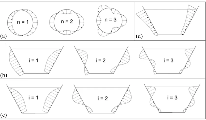
Fig. 2-4 Distribution of different pressure modes: (a) Circumferential distribution, (b) Vertical distribution for impulsive pressure modes n=1, 3, 5, .. , (c) Vertical distribution for impulsive pressure modes n=2, 4, 6, .., (d) Vertical distribution for
fundamental sloshing pressure mode
As a result of the decoupling between liquid sloshing modes and shell vibration modes, the sloshing component PS(r,θ,z,t) can be evaluated assuming the tank walls are rigid. Based on this assumption, El Damatty et al. (2000) derived an expression for the fundamental sloshing component of the hydrodynamic pressure as follows
PS(r,θ,z,t) = B(t) ρF J1(k1r) cosh(k1z)cos(θ) [2-7]
where J1(k1r) is the Bessel’s function of the first kind of order one, B(t) is arbitrary function of time, and ρFis the fluid density. A procedure to evaluate the constant k1 was
discussed in detail by El Damatty et al. (2000). The vertical distribution for the fundamental sloshing pressure mode is shown in Fig. 2-4d. Details of the impulsive and sloshing pressure derivations are found in Appendix D.
(a)
(b)
(c)
2.3 Finite
Element
Model
In this study, three-dimensional numerical models are developed for steel conical tanks using the finite element method. The numerical model is based on a consistent 13 noded subparametric triangular shell element shown in Fig. 2-5a, which was developed by Koizey and Mirza (1997). This element has the advantages of being free of the spurious shear modes, i.e., locking phenomenon observed in isoparametric shell elements when used in modeling thin shell structures. El Damatty et al. (1997d) extended the formulation of this shell element to include geometric and material non-linearities. Accordingly, this model can be used to predict both elastic and inelastic buckling. Due to symmetry about the horizontal axis in both loading and geometry, only half of the cone is modelled and used in the analysis. A mesh sensitivity analysis was performed in order to determine the mesh size that is able to capture the expected buckling accurately. It is found that a mesh of 512 triangular elements as shown in Fig. 2-5b is sufficient to accurately capture the buckling waves near the tank base.
The length of the elements is not uniform as the mesh is chosen to be finer near the base of the tank due to the stress concentration at this location where buckling is expected to occur. The tanks are assumed to be hinged at the base along the circumference and free at the top.
Fig. 2-5 (a) Coordinates and degrees of freedom for a consistent shell element, (b) Finite element mesh for half cone
2.4 Method
of
Analysis
In this study, non-linear static analysis, commonly known as pushover analysis, is used to obtain the load-carrying capacity of the conical tanks. The non-linear static analysis is carried out by increasing the load value incrementally till reaching failure, which is in the form of buckling of the steel vessel. The load increase is achieved using an increasing load factor, which is multiplied by the applied hydrodynamic pressure load pattern. The linearity in the analysis comes from the inclusion of both geometric and material non-linearity in the finite element model previously discussed. To include both the hydrostatic and hydrodynamic pressure in the analysis, two load factors are used. The first is PHS,
which corresponds to the hydrostatic pressure while the second is PHD, which corresponds
to the hydrodynamic pressure. The analysis starts with a value of the load factor PHD equals
to zero and then the load factor PHS is increased incrementally until it reaches the actual
value of the hydrostatic pressure acting on the tank. After this stage, the value of PHS is
kept constant and the value of PHD begins at zero and increases until failure occurs. At the
end of the analysis, the value of PHD at failure is recorded along with the deformations,
forces, and stresses corresponding to the failure value. It should be noted that the load increments near the failure are reduced in order to better capture the failure load factor. This is achieved by doing more than one trial for each analysis.
A group of 75 tanks of practical dimensions are chosen for this study with Rb ranging from
4.0m to 6.0m, h from 5.0m to 9.0m, and θv = 30o, 45o, 60o withsteel yield stress of 300