Impact of Medium Randomness on Radar Detection Accuracy
with Plane E-Wave Polarization
Hosam El-Ocla*
Abstract—Investigation of backscattering enhancement of waves propagation in random medium is a crucial factor in remote sensing. Medium effects on waves backscattering are important to measure the error rate in radar detection of targets with a finite size. In this paper, we present numerical results for the backscattering enhancement factor assuming different medium parameters and target configuration. Convex illumination region of partially convex surface is assumed. We consider targets to take large sizes of about five wavelengths and a plane wave incidence in the far field. Waves propagation and scattering from objects are calculated in free space and random medium while consideringE-polarization of incident wave.
1. INTRODUCTION
Electromagnetic waves formulation is a task that have attracted researchers over decades. Several interesting methods were presented such as Finite Element Method (FEM) [1] and Method of Moment [2]. One of the major concerns of these methods is the requirement of a relatively long computational time in addition to the memory space that would be barely available particularly for large size objects needed in the realistic bodies such as aircraft. Fast Multiple Method (FMM) [3] is alternative method aiming to reduce the processing time but yet not that enough for large and targets having complex cross sections. However, these methods presented high level of accuracy.
Another successful method that uses a current generator operator has proved to be efficient to formulate waves scattering from conducting cylinders. This method was introduced in [4, 5] based on Yasuura’s method [6]. Current generator method (CGM) is valid for an arbitrary shaped object that can be embedded in a random medium such as turbulence. The current generator operator is to calculate the electromagnetic field on the whole surface of the cylinder including the shadow region. In this regard, results for radar cross-section (RCS) of typical convex cylinders were presented in [7]. On the other hand, objects having inflection surfaces formed by concave–convex boundaries should be considered to meet the expectations of radar applications. Investigating target effects was pursued in some articles [8–10]. Our results are in excellent agreement with those assuming a cylinder with circular cross section in free space in [11]. Lately, CGM was verified using FDFD method and proved a fair agreement with an accuracy below 5% error rate for objects in random media and even less error in the free space [12].
To probe the accuracy of RCS in disordered medium, backscattering enhancement (BE) phenomenon should be considered. BE is produced due to the double passage effect on waves propagation in a random medium and this was examined in several articles [13–16]. Accordingly, the ideal BE factor in random medium is two. This BE factor might be altered by several parameters such as object configuration and medium randomness parameters. Deviation of the BE factor from
Received 4 March 2018, Accepted 30 April 2018, Scheduled 10 May 2018 * Corresponding author: Hosam El-Ocla ([email protected]).
two reveals having an error in the RCS value and this should be avoided through precious selection of the range where the variation in the BE factor is minimal. In this paper, we work on the analysis of BE and consider both medium fluctuations intensity expressed by the medium correlation function and the spatial coherence length (SCL) of waves around the object. While a plane is flying, it may go through different media, such as fog, haze, mist, and rain, where these parameters differ and that is why we consider media having various values in our simulation. Targets are to take large sizes up to five wavelengths with convex illumination region. Axial polarization (E-wave incidence) is assumed. The time factor exp(−iwt) is assumed and suppressed in the following section.
2. SCATTERING PROBLEM
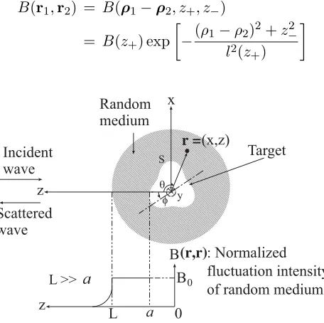
Geometry of the problem is shown in Figure 1. A random medium is assumed as a sphere of radiusL around a target of the mean size a L, and also to be described by the dielectric constant ε(r), the magnetic permeability μ, and the electric conductivityσ. For simplicity ε(r) is expressed as
ε(r) =ε0[1 +δε(r)] (1)
whereε0 is assumed to be constant and equal to free space permittivity andδε(r) is a random function with
δε(r)= 0, δε(r1)δε(r2)=B(r1,r2) (2)
and
B(r1,r2)1, kl(r)1 (3)
Here, the angular brackets denote the ensemble average;B(r1,r2),l(r) are the local intensity and local scale-size of the random medium fluctuation, respectively;k=ω√ε0μ0 is the wavenumber in free space. Also μ and σ are assumed to be constant; μ=μ0, σ = 0. For practical turbulent media the condition in Eq. (3) may be satisfied. Therefore, we can assume the forward scattering approximation and the scalar approximation [17]. As shown in Figure 1, when an incident wave propagated along thezaxis is scattered and observed at a point close to the z axis, we can approximately express Eq. (2) under the condition in Eq. (3) as follows:
B(r1,r2) = B(ρ1−ρ2, z+, z−)
= B(z+) exp
−(ρ1−ρ2)2+z−2 l2(z
+)
(4)
θ
φ
r =(x,z)
L
Target Random
medium x
z
z Incident wave
Scattered wave
0 B(r,r)
B0 S
: Normalized fluctuation intensity of random medium
a
y
L >> a
where r= (ρ, z),ρ=ixx+iyy, z+= (z1+z2)/2, z−=z1−z2, and lis the local scale-size at z+, and where
B(z+) =
B0, z0≤z+ ≤L
B0(z+/L)−n, z+≥L (5)
l(z+) = l0 (6)
z0 = a. (7)
where n denotes the normalized thickness of transition layer from the random medium to free space; n >1 andn= 2,3.
Consider the case where a directly incident wave is produced by a line source f(r) distributed uniformly along the y axis. Then, the incident wave is cylindrical and becomes plane approximately around the target because the line source is very far from the target. The line source is located at rt, that is beyond the target propagates and illuminates the target and induces a surface current on the target. A scattered wave from the target is produced by the surface current and propagates back to the observation point that coincides with the source point. That is, the monostatic scattering is considered under the condition that the backscattering enhancement occurs [18]. The target is assumed to be a conducting cylinder of which cross-section is expressed by
r =a[1−δcos 3(θ−φ)] (8)
where φ is the rotation index and δ is the concavity index. We can deal with this scattering problem two dimensionally under the condition in Eq. (3); therefore, we represent ras r= (x, z). Assuming an axial polarization of incident waves (E-wave incidence), we can impose the Dirichlet boundary condition for wave fieldu(r) on the cylinder surfaceS. That is, u(r) =0, whereu(r) represents Ey.
Here, let us designate the incident wave byuin(r), the scattered wave by us(r), and the total wave by u(r) = uin(r) +us(r). According to our method [5], using the current generator YE and Green’s function in random mediumG(r|r), we can express the scattered wave as
us(r) =
Sdr1
Sdr2[G(r|r2)YE(r2 |r1)uin(r1|rt)] (9) Here, YE is the operator that transforms incident waves into surface currents on S and depends only on the scattering body. The current generator can be expressed in terms of wave functions that satisfy Helmholtz equation and the radiation condition. That is the surface current is obtained as
SYE(r2 |r1)uin(r1 |rt) dr1 Φ
∗
M(r2)A−E1
S
ΦTM(r1), uin(r1|rt)
dr1 (10)
where
S
ΦTM(r1), uin(r1 |rt)
dr1≡
S
φm(r1)∂uin
(r1 |rt)
∂n −
∂φm(r1)
∂n uin(r1|rt)
dr1 (11)
Above equation is sometimes called “reaction” named by Rumsey [19]. In Eq. (10), the basis functions
ΦM are called the modal functions and constitute the complete set of wave functions satisfying the Helmholtz equation in free space and the radiation condition;ΦM = [φ−N, φ−N+1, . . . , φm, . . . , φN], Φ∗M and ΦTM denote the complex conjugate and the transposed vectors of ΦM, respectively; M = 2N + 1 is the total mode number; φm(r) =Hm(1)(kr) exp(imθ); AE is a positive definite Hermitian matrix given by
AE =
⎛ ⎝
(φ−N, φ−N) . . . (φ−N, φN) ..
. . . . ... (φN, φ−N) . . . (φN, φN)
⎞
⎠ (12)
in which its m, n element is the inner product of φm and φn:
(φm, φn)≡
Sφm(r)φ
∗
n(r)dr (13)
Assuminguin(r1 |rt) =G(r1 |rt), the average intensity of backscattering wave for E-wave incidence is given by
|us(r)|2 =
Sdr01
Sdr02
Sdr
1
Sdr
2YE(r01|r1)YE∗(r02|r2)
×G(r|r1)G(r|r01)G∗(r|r2)G∗(r|r02) (14) When we consider wave propagation through a continuous random medium, Green’s function in Equation (14) has approximately a complex Gaussian probability distribution in an isotropic random medium [5, 20]. As a result, to solve the fourth moment of Green’s function in Equation (14), structure function of the turbulenceD is used [21]. Random medium condition in Equation (3) assumes that the randomness intensity, B, is low enough such that the medium has a quite small number of particles, which leads to having large separations, ρ, among particles. In [22], it was demonstrated that D agrees better with the two-dimensional isotropic relation for widerρamong particles than for narrower ρ. It was deduced that a random medium can be assumed as a two-dimensional turbulence in the enstrophy inertial range. This was derived and compared with calculations based on wind data from 5754 airplane flights. Consequently, three-dimensional problems can be analyzed two-dimensionally under the condition of Equation (3) in the absence of vortex stretching the nonlinear inertial force in the direction of the y axis of the cylinder that is aligned with the line source. We can obtain the RCS by using Equation (14)
σ=|us(r)|2·k(4πz)2 (15)
3. NUMERICAL RESULTS
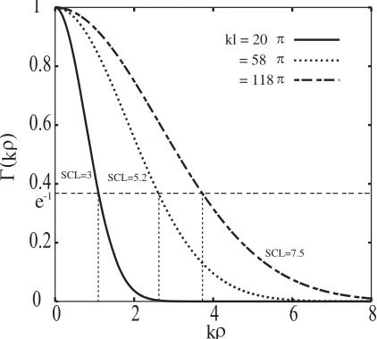
Although the incident wave becomes sufficiently incoherent, we should pay attention to the spatial coherence length of the incident wave around the target (SCL) [8–10]. The degree of spatial coherence is defined by
Γ(ρ, z) = G(r1 |rt)G
∗(r
2 |rt) |G(r0 |rt)|2
(16)
where r1 = (ρ,0),r2 = (−ρ,0), r0 = (0,0),rt = (0, z). SCL is the length around the object in the far field where the electromagnetic waves maintain a certain degree of coherence determined by Equation (16). In our results, we assume B(r,r) = B0 and kB0L = 4.8π, 0.48π for B0 = 8 ×10−4,8×10−5, respectively; therefore the coherence attenuation index α defined as k2B0Ll/4
0
0.2
0.4
0.6
0.8
1
0
2
4
6
8
kl = 20
= 118π
π
= 58 π
( ρ)Γk
SCL=7.5 SCL=5.2
SCL=3
ρ k e-1
given in Reference [5] is 24π2,69.6π2,141.6π2 for B0 = 8×10⁻⁴ and α = 2.4π2,6.96π2,14.16π2 for B0 = 8×10⁻⁵, respectively, which means that the incident wave becomes sufficiently incoherent. The SCL is defined as the 2kρ at which |Γ|=e−1 0.37. Figure 2 shows a relation between SCL and kl in this case and that the SCL is equal to 3, 5.2 and 7.5 assumingB0 is 5×10⁻⁴. These various values of B0 and SCL are postulated in our calculations to evaluate the performance of the backscattering enhancement in different media.
Here, we point out thatN in Eq. (12) depends on the target parameters and polarization of incident waves. For example, we choose N = 24 at δ = 0.1 for E-wave incidence in the range of 0.1< ka < 5; at ka = 20, we choose N = 40 at δ = 0.1. As a result, our numerical results are accurate because these values of N lead to convergence of RCS. CGM is valid for large sizes of objects and that should enlargeN in a way that would maximizes the calculation time. To have a reasonable calculation time, computation of scattering data has been restricted to the interval 0.1 < ka < 30 where the target mean size a is about five wavelengths. It is quite difficult to exceed this ka’s limit since larger ka requires quite large M, used in Equations (10) and (11), which consequently enlarges the calculation
1.6 1.7 1.8 1.9 2 2.1
0 5 10 15 20 25 30
= 8 10 = 0
_ 4
8 10_ 5
ka
/
01.6 1.7 1.8 1.9 2 2.1
0 5 10 15 20 25 30
= 8 10
=
0
_ 4
8 10_ 5
ka
1.6 1.7 1.8 1.9 2 2.1
0 5 10 15 20 25 30
ka
= 8 10
=
0
_ 4
8 10_ 5
σ
σ
/
0
σ
σ
/
σ
0σ
Β Β
Β ∗
∗
∗ ∗
∗ ∗
(a) (b)
(c)
time dramatically. This implies that CGM can be used in a range of frequencies from HF to about VHF depending on the object sizea.
Based on the assumption of waves coherence completion in the propagation of distance 2a, let us define the effective illumination region (EIR) as the surface that is illuminated by the incident wave and restricted by the SCL. Therefore, we expect that the target configuration including δ and katogether with SCL is going to influence the EIR and accordingly NRCS in a way that will be analyzed in the following results.
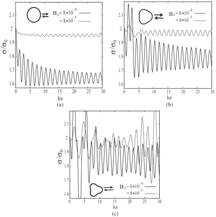
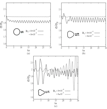
To evaluate the BE behavior, we conduct numerical results for the normalized RCS (NRCS), defined as the ratio of RCS in random media σ to RCS in free space σ0. In Figures 3 to 5, we analyze results for effects of random medium parameters including SCL and fluctuations intensityB0 defined in Equations (2) to (5). Also, we discuss effects of target configuration including normalized target mean size kaand concavity index δ on the NRCS.
We consider that RCS calculation is based on the plane waves scattering from cylinders in free
1.6 1.7 1.8 1.9 2 2.1
0 5 10 15 20 25 30
σ
/
0
ka
= 8 10
=
0
_ 4
8 10_ 5
1.6 1.7 1.8 1.9 2 2.1
0 5 10 15 20 25 30
= 8 10
=
0
_ 4
8 10_ 5
ka
1.6 1.7 1.8 1.9 2 2.1
0 5 10 15 20 25 30
= 8 10
=
0
_ 4
8 10_ 5
ka
σ
σ
/
0
σ
σ
/
0
σ
Β
Β
Β
∗∗
∗ ∗
∗ ∗
(a) (b)
(c)
1.6 1.7 1.8 1.9 2 2.1
0 5 10 15 20 25 30
= 8 10
=
0
_ 4
8 10_ 5
σ /
0
ka
(a)
1.6 1.7 1.8 1.9 2 2.1
0 5 10 15 20 25 30
= 8 10
=
0
_ 4
8 10_ 5
ka
1.6 1.7 1.8 1.9 2 2.1
0 5 10 15 20 25 30
= 8 10
=
0
_ 4
8 10_ 5
ka
(c)
σ
σ /
0
σ
σ /
0
σ
Β Β
Β ∗
∗ ∗∗
∗ ∗
(b)
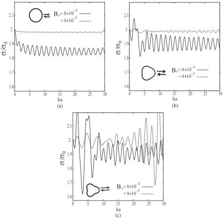
Figure 5. As Figure 3, but for SCL = 7.5.
space as the ideal reference data. When ka−→0, the object tends to be a point target where the BE factor expressed in NRCS has the value of two as a result of the double passage effect [13]. Deviation of NRCS from two reflects the error rate in the RCS in random medium compared to the free space case and our goal is to select that range ofkawhere NRCS keeps having this value with minimum variation. On the other hand, when a plane is sensed at different spots while it is moving, RCS would vary as a result of the backscattering from different illumination regions where δ is different, e.g., compare between fuselage incidence to wings incidence and other parts. Minimizing this difference in RCS and NRCS is another challenge to reduce the error in object identification.
smaller value, EIR shrinks while having smaller number of stationary and inflection points especially those complex ones [26, 27] and, therefore, NRCS oscillations have lower peaks and this reveals less impact of resonance; e.g., compare Figure 3(a) to Figures 3(b) and 3(c), Figure 4(a) to Figures 4(b) and 4(c) and Figure 5(a) to Figures 5(b) and 5(c). We can see such effects of complex inflection points as well with intricate cross-sections, whereδ has bigger values, on NRCS as it has irregular fluctuations compared to small values ofδ including circular cylinder where it is a typical convex surface withδ= 0. This effect of complex inflection points is valid in all ranges of target size compared to the wavelength. With wider SCL around the object, waves are more in-phase, so the resonance has less peaks of NRCS; e.g., compare Figure 3(a) to Figures 4(a) and 5(a).
In the rangea > λ, NRCS oscillations have less strength away from the resonance region particularly with δ = 0. It is noticed that peak-to-peak NRCS oscillations gradually reduce because of shortage of the generated surface current. Hence, effects of medium parameters includingB0 and SCL would decay when a λ. On the other hand, shadow region would have smaller contributions to the scattered waves whenka SCL where the EIR acts as being a flat surface.
NRCS is closer to two with weaker correlation function B0 in Equation (5) as a result of the relatively low absorption of the medium which, in turn, enlarges the scattering waves intensity, defined in Equation (14), in random medium compared to the free space case and this agrees with [28]. This is more obvious when the object contour has less complexity (e.g., compare Figure 3(a) to Figures 3(b) and 3(c)). As pointed out earlier, stationary and complex inflection points would contribute excessive waves when the cross section of the object is more complex (e.g.,δ = 0.2) which are absent whenδ = 0 and as a result, B0 has more effect on the NRCS of such complex contour; e.g., compare Figure 3(c) to Figure 3(a). When SCL is small, waves transverse suffers relatively acute turns on the edges of particles. Consequently, waves scatter in a way spreading in wider range through medium particles, and hence B0 would have more effect on the scattering intensity. In other words, NRCS differs obviously withB0 when SCL has a shorter length (SCL = 3) compared to wider length of SCL (SCL = 5.2 and 7.5) as shown in Figures 3(a), 4(a) and 5(a) compared to other results where NRCS is evidently different with B0.
As a result, propagation of waves in a medium where its correlation intensity B0 is low and/or having a wider SCL would reduce the impact of the medium on the RCS, and consequently, NRCS performance would be obviously acting as in the double passage effect. This implies that the deviation of the BE factor from two is limited, and consequently, the error rate is minimized. This low error rate can be more supported in the high frequency range whereaλ.
4. CONCLUSION
In this paper, we have numerically analyzed the effect of medium parameters and object configuration on the BE. RCS of a conducting cylinder is calculated numerically in free space and random medium such as turbulence. Using RCS, we could obtain the BE factor represented in the normalized RCS. We have considered medium randomness parameters including the spatial coherence length (SCL) around the target and the fluctuations intensity B. We have focused on the E-polarization using the CGM.
Mainly we aim to improve the radar detection accuracy through minimizing the deviation strength of the BE factor. This is to reduce the error rate of the RCS calculation in random medium. To achieve this goal, electromagnetic waves should be in the high frequency range where a λ. In this range, radar detection would be more precious away from the effect of the resonance region where the intense oscillations in the BE factor would reflect inaccurate RCS calculation. In other words, resonance effect has a limitation on the CGM accuracy at the low frequency band and hence CGM is a high frequency method. Also, in the high frequency range, medium parameters and object configuration effects would be relatively minimal, and the double passage would have a dominant effect.
REFERENCES
2. Rao, S. M., D. R. Willton, and A. W. Glission, “Electromagnetic scattering by surface of arbitrary shape,” IEEE Trans. on Antennas and Propagation, Vol. 30, 409–418, May 1982.
3. Engheta, N., W. D. Murphy, V. Rokhlin, and M. S. Vassiliou, “The Fast Multipole Method (FMM) for electromagnetic scattering problems,”IEEE Trans. Antennas Propagat., Vol. 40, No. 6, 634–641, 1992.
4. Tateiba, M. and E. Tomita, “Theory of scalar wave scattering from a conducting target in random media,” IEICE Trans. Electron., Vol. E75-C, No. 1, 101–106, 1992.
5. Tateiba, M. and Z. Q. Meng, “Wave scattering from conducting bodies in random media — Theory and numerical results,” Progress In Electromagnetics Research, Vol. 14, 317–361, 1996.
6. Tateiba, M., “A general aspect of Yasuura’s method for analyzing scattering problems,” Proc.
Sino-Japan Joint Meeting on Optical Fibre Science and Electromagnetics Theory, 78–83, 1997.
7. Meng, Z. Q. and M. Tateiba, “Radar cross sections of conducting elliptic cylinders embedded in strong continuous random media,” Waves in Random Media, Vol. 6, 335–345, 1996.
8. El-Ocla, H. and M. Tateiba, “Backscattering enhancement for partially convex targets of large sizes in continuous random media for E-wave incidence,”Waves in Random Media, Vol. 12, No. 3, 387–397, 2002.
9. El-Ocla, H., “Backscattering from conducting targets in continuous random media for circular polarization,” Waves in Random and Complex Media, Vol. 15, No. 1, 91–99, 2005.
10. El-Ocla, H., “Targets configuration effect on waves scattering in random media with horizontal polarization,” Waves in Random and Complex Media, Vol. 19, No. 2, 305–320, 2009.
11. Kerker, M., The Scattering of Light and Other Electromagnetic Radiation, Academic Press, New York, 1969.
12. Al Sharkawy, M. and H. El-Ocla, “Electromagnetic scattering from 3D targets in a random medium using finite difference frequency domain,”IEEE Transactions on Antenna and Propagation, Vol. 61, No. 11, 5621–5626, 2013.
13. Kravtsov, Yu. A. and A. I. Saishev, “Effects of double passage of waves in randomly inhomogeneous media,” Sov. Phys. Usp., Vol. 25, 494–508, 1982.
14. Jakeman, E., “Enhanced backscattering through a deep random phase screen,” J. Opt. Soc. Am., Vol. 5, No. 10, 1638–1648, 1988.
15. Ishimaru, A., “Backscattering enhancement: From radar cross sections to electron and light localizations to rough surface scattering,” IEEE Antennas and Propagation Magazine, Vol. 33, No. 5, 1–7, 1991.
16. Mishchenko, M. I., “Enhanced backscattering of polarized light from discrete random media: Calculation in exactly the backscattering direction,” J. Opt. Soc. Am., Vol. 9, No. 6, 978–82, 1992.
17. Ishimaru, A., Wave Propagation and Scattering in Random Media, IEEE Press, 1977. 18. Ishimaru, A., IEEE Antennas and Propagation Magazine, Vol. 33, 7–11, 1991.
19. Rumsey, V. H., “Reaction concept in electromagnetic theory,” Physical Review, Vol. 94, 1483–91, 1954.
20. Tateiba, M., “Multiple scattering analysis of optical wave propagation through inhomogeneous random media,” Radio Science, Vol. 17, No. 1, 205–210, 1982.
21. El-Ocla, H. and M. Al Sharkawy, “Using CGM and FDFD techniques to investigate the radar detection of 2D airplanes in random media for beam wave incidence,” IEEE Antenna and
Propagation Magazine, Vol. 56, No. 5, 91–100, 2014.
22. Lindborg, E., “Can the atmospheric kinetic energy spectrum be explained by two dimensional turbulence?,”Journal of Fluid Mechanics, Vol. 388, 259–288, 1999.
23. Ishimaru, A., Electromagnetic Wave Propagation, Radiation, and Scattering, Prentice Hall, 1991. 24. Rocca, P. and A. F. Morabito, “Optimal synthesis of reconfigurable planar arrays with simplified
25. El-Ocla, H. and M. Tateiba, “The effect of H-polarization on backscattering enhancement for partially convex targets of large sizes in continuous random media,” Waves in Random Media, Vol. 13, No. 2, 125–136, 2003.
26. Ikuno, H. and L. B. Felsen, “Complex ray interpretation of reflection from concave-convex surface,”
IEEE Transactions on Antennas and Propagation, Vol. 36, No. 9, 1260–1271, 1988.
27. Ikuno, H. and L. B. Felsen, “Complex rays in transient scattering from smooth targets with inflection points,” IEEE Transactions on Antennas and Propagation, Vol. 36, No. 9, 1272–1280, 1988.
28. Rim, Y. H., “Forward scattering of light in inhomogeneous binary dielectric media,” Physical