Implementation and calibration of a multi sensor measuring
system
Jan B¨ohm, Jens G¨uhring, Claus Brenner
aInstitute for Photogrammetry (ifp)
University of Stuttgart
Geschwister-Scholl-Straße 24, D-70174 Stuttgart, Germany
ABSTRACT
We present our work on the implementation and calibration of a multi sensor measuring system. The work is part of a large scale research project on optical measurement using sensor actuator coupling and active exploration. This project is a collaboration of researchers from seven institutes of the University of Stuttgart including photogrammetry, mechanical engineering and computer science. The system consists of optical sensors which can be manipulated in position and orientation by robot actuators, and light sources which control illumination. The system performs different tasks including object recognition, localization and gauging. Flexibility is achieved by replacing the common serial measurement chain by nested control loops involving autonomous agents which perform basic tasks in a modular fashion. The system is able to inspect and gauge several parts from a set of parts stored in a 3-D model database. The paper gives an overview of the entire system and details some of the photogrammetry-related aspects such as the calibration of the different sensors (cameras, stereo-head, stripe projector), the calibration of the measurement robot using photogrammetric measurements, as well as data processing steps like segmentation, object pose determination, and gauging.
1. INTRODUCTION
In the past few years we have seen a tremendous growth in the number of 2-D and 3-D vision system for inspection and gauging. Their speed, flexibility and accuracy has made optical measurement system quite popular for many applications in industry. Currently we can observe a trend, mainly at automobile manufacturers, to replace static measurement setups with flexible measurement units using general purpose robots, which perform a series of mea-surements using a single sensor. This new generation of measurement systems is characterized by certain limitations. Typically they consist of only one single type of sensor, often a laser triangulation sensor. Usually the sensor can perform only a single measurement task, such as edge measurement. If several of these systems are combined to form a larger set up, they perform their task independently and without interaction. All motions are pre-programmed, usually they have been taught by hand. The system performs repetitive measurements of a single class of objects.
It is our and our partners vision to design a system which is to overcome these limitations. We aim at implementing a highly flexible measurement system using several different types of sensors. Flexibility to us has two meanings, for one we wish to be flexible in what we measure i.e. the kind of objects we aim at and second in how we do it i.e. what sensors we use. Our system is not designed for a single class of objects but for a large variety of objects varying in size, shape and material. Using different types of sensors we exploit the possibility of combining sensors and illumination devices such that we achieve the optimal setup for the specific task. The single steps of a measurement sequence shall not be chosen by hand but are to be computed automatically on the basis of a given CAD model and the ability to actively explore the scene.
2. THE PROJECT
The goal of our work is to implement an optical measurement system flexible enough to handle a large variety of objects from the industrial world. Using different types of sensors, e.g. mono cameras, stereo cameras and stripe projection systems, the measurement process is automatically tailored towards the object presented to the system and measurement tasks specific to the object are executed. A CAD model for each object forms the basis for measurement
planning and assessment. We allow the objects to be presented to the system in arbitrary position. The system has to recover the pose of the object automatically.
The goals of this project are rather ambitious and the issues to be resolved are from a broad range of scientific areas. It is not possible to attempt to implement such a system without interdisciplinary collaboration. It is for this reason that the University of Stuttgart has established a large scale research project funded by the German Science Foundation. The project is a cooperation of seven institutes of the University from all major areas of engineering: mechanical engineering, electrical engineering, optical engineering, computer science and photogrammetry. The different disciplines all have contributed their specific capabilities and know-how for the broad range of issues:
• mechanical design and robotics for sensor positioning
• sensor technology, optics and lighting technology
• CAD technology, measurement planning
• Software system design, distributed computing and machine learning
• sensor and actuator calibration, high precision imaging
• image processing, object recognition and modeling
Altogether more than 15 researchers are occupied with this project. In addition a large number of students is involved. The project was started in the beginning of 1998 and has now completed its first phase. It has been decided to extend the project over the next three years until 2002.
3. SYSTEM DESIGN
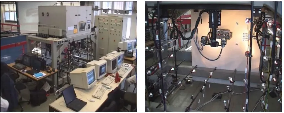
We have created a test bed in order to validate our concepts in real-world experiments and to be able to refine and improve our measurement strategies. At the moment our experimentation environment consists of a portal machine (see figure 1) which uses linear motor like drives to move three independent platforms within a measurement volume of approximately 1m3. The platforms are hanging upside down from the ceiling of the measurement cell, attracted to the ceiling by permanent magnets but floating on thin air cushions. Electric magnets are the drives which move the platform along a regular grid engraved onto the metallic ceiling. The grid on the ceiling forms a two dimensional coordinate system along which the platforms can be positioned with high repeatability and accuracy. Each of the platforms is equipped with a serial link arm. The number of axes ranges from one to three. Three platforms independently moving in two axes, one with a single, the other two with three additional axes total a system with 13 axes.
The complexity of the machine has several implications. For one the possibility of moving three platforms independently within a common volume allows for a number of sensor interactions and combinations. The high number of controllable axes creates the possibility to position the sensors in a most flexible way. This makes it possible to move the sensor to its optimal position with respect to the measurement task. Sensor positioning can be vital in cases of reflecting surfaces or complex shaped objects.
One of the drawbacks of the complexity in the kinematics of course is the increased complexity in motion compu-tation. Advanced algorithms of motion planning, collision avoidance and kinematics in general have to be applied. Bringing all the separate modules into one and the same coordinate frame becomes a major issue when measurement results obtained from different sensors have to be merged and evaluated.
3.1. Sensors
The idea behind designing a multi sensor system is the possibility to choose from an assortment of sensors the ones which are best suited for a particular task, depending on several conditions such as object size, shape, material and desired accuracy. The sensors should not overlap in their capabilities but rather complement one another.
Figure 1. The measurement cell and a view inside the measurement volume with one of the sensors in the front and a part in the back.
can achieve high accuracy best when the sensors field of view (FOV) is narrowed down to the part of the object to be inspected.
At the current stage we have integrated three sensors in the mechanical platform and we have developed a fourth sensor which will possibly be integrated in the future. A motorized zoom lens camera which has the largest FOV of all of our sensors is mainly used for object localization and active exploration of unknown scenes. The cameras focal length can be varied in a broad range. In addition it has a large range of focus. The cameras FOV starts at 26mm distance where it is able to achieve a resolution of 21 lines permmat maximal focal length. At the other end, at a distance of 1m(the maximum within our mechanical platform) it reaches a FOV of 960mm x 720mm. This makes it ideally suited to inspect any kind of object independent of its size. In addition the camera has both a motorized focus and iris. Further camera parameters such as exposure time and gain can also be remotely controlled.
These features make it our most flexible sensor. Several algorithms have been implemented to exploit this flexibility. An auto-focus algorithm as well as an auto-iris and an auto-FOV algorithm have been implemented. The auto-FOV adapts the cameras focal length so that the object is imaged at its maximum size occupying the whole of the cameras imaging sensor. The camera can be used for 2D imaging tasks such as 2D object recognition and in combination with a stripe projection device it can even be used for 3-D imaging, albeit only lower accuracy can be expected.
While a zoom lens camera with motorized lenses gives great flexibility we also have to mention some of the disadvantages. The optomechanic accuracy of a motorized lens can not be compared to that of a fixed focus lens. We observe slight deviations in the repeatability of the motor positions. This leads to measurement errors with a standard deviation of up to 1.7µmin image space at a pixel size of 6.7µm(see Figure 2).
The second sensor is a high precision stereo camera. The cameras are high resolution (1k x 1k) digital cameras equipped with 17 mm focal length quality lenses. The stereo head has a calibrated fixed base length. The sensor is used for precise 3-D measurement of distinct object features such as drill holes, edges and corner points. In combination with a stripe projector it can also be used for large FOV dense surface measurements. The third sensor is called LASCAM (laser camera) and consists of a laser stripe projector in combination with a CCD camera. The sensor is used for dense 3D surface measurements with a smaller FOV of 40mmx 40mm. The forth sensor which is currently not integrated in the machine is a stereo stripe projection microscope. It uses one optical path to project a stripe sequence and the other for image acquisition. It is capable of taking dense range images of a very small area down to 1mm2, useful for detection of small surface defects and to determine surface roughness.
3.2. Software Architecture
(a) (b) -0.0025 -0.002 -0.0015 -0.001 -0.0005 0 0.0005 0.001 0.0015 0.002 0.0025
-0.0015 -0.001 -0.0005 0 0.0005 0.001 0.0015 ’106_mean’ ’108_mean’
(c)
Figure 2. Retrieving the same step-motor position of the motorized focus several times in an otherwise fixed setup leads to small errors in image measurement. (a) The first image in a sequence of experiments. (b) Difference of two images at the same focus position. (c) The deviation of image coordinates inmmof two target centers in a sequence of five images.
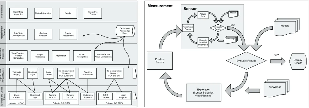
Actuator 3 (3 DOF) Actuator 2 (5 DOF)
Actuator 1 (5 DOF)
Ph ysi ca lL ev el (Dev ic es and D ev ic e Dri vers ) Logi ca lL ev el (V irtu al D evi ce s) E xpl orat io n / P roc es si ng Ta sk In te rp re ta tio n / Asse ssme nt of Res ul ts U se rIn te rfa ce Thematic Imaging 3D-Measurement System -FOV 50x50 cm2
3D-Measurement System -FOV 5x5 cm2
Adaptive Illumination
Zoom
Camera DirectionalLight Camera1K x 1K Camera1K x 1K MultimediaProjector CameraCCIR ProjectorLaser Stereo Camera Directional Light ... ... Image
Processing Registration RecognitionObject Strategy
Selection Start / Stop
Inspection Status Information Results InteractiveControl
Sub-Task Decomposition
View Planning / Sensor Scheduling Nominal/Actual Value Comparison Quality Assessment CAD-Data / Knowledge Base Evaluate Results Models Display Results Exploration (Sensor Selection, View Planning) Position Sensor Knowledge OK? Evaluate Results Models Acquire Data Compute Modified Parameters Reconfigure Sensor Knowledge Sensor Measurement OK?
has to be adjusted whenever hardware changes other software is of more general use.
The experimental character of our system implies constant change and therefore calls for an adequately flexible software system design. A monolithic software structure is not sufficient for our purpose. Likewise the amount of parallelism inherent in the system, for example parallel movement of the sensors, parallel movement and image acquisition or processing, calls for a software system design which allows for distributed computing rather than the classical sequential approach.
We have successfully designed and implemented a distributed object oriented software architecture based on industry standard CORBA (Common Object Request Broker Architecture).1 CORBA is available cross-platform and so we are able to combine different computing platforms within one system which eases development. Within the CORBA framework we establish so called autonomous agents2which can offer services and also request services from other agents. The autonomous agent concept encapsulates software components specific to certain hardware and can be easily updated or replaced when hardware changes. The concept has proven to be an excellent tool to cope with the problems of a large and complex system.
4. SYSTEM CALIBRATION
Calibration is probably the most fundamental aspect in the implementation of any measurement system. However, its importance and complexity is often seriously underestimated. In this context calibration means both, sensor calibration as well as the calibration of the machine itself.
4.1. Actuator Calibration
Actuator calibration is necessary to determine the geometric relationship among the measurement machine, the different sensors and a reference frame. In our case, the reference frame or world coordinate frame is located in the base plate of the measurement volume and is represented by a number of targets that are known with high accuracy. The base coordinate frame is located in the ceiling and was provided by the manufacturer. It is the coordinate frame, to which all the transformations inside the machine refer to. The kinematic model of the machine allows us to transform from the flange coordinate system, which is defined on the mounting surface of the end-effector, to the base coordinate frame. The sensor coordinate frame, is the natural coordinate frame for raw measurements. It is linked to the flange coordinate frame by the hand-eye transformation. At the moment, we assume the base to flange geometry to be accurate and stable. Hence, we are only concerned with the identification of the base and hand-eye transformations.
We are using a calibration procedure that is tailored to our measurement system. The base transformation is determined using a high resolution camera. The camera is moved to a number of positions. At each position, it acquires a set of images while the camera is rotated around the axes of revolution. For each image, the position of the camera is computed by resection, allowing us to resolve the position and orientation of these axes in the world coordinate frame. The intersection point of the two axes in world coordinates is also known in the base coordinate frame thus allowing us to compute the base-to-world transformation.
Once the base-to-world transformation is known, the position and orientation of each sensor is computed by resection. Since the position and orientation of the flange coordinate frame is known by the forward kinematic of the machine, the hand-eye transformation for each sensor can be calculated in a straightforward manner.
4.2. Sensor Calibration
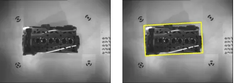
Figure 4. Coarse object localization.
orientation must also be determined. The stripe projection systems are either modeled as inverse cameras or used as an aid to establish point correspondences between at least two cameras e.g. the cameras of the stereo head.
Despite the existence of techniques in photogrammetry to simultaneously estimate these parameters during mea-surement tasks, we are using a specially designed test object to effectively compute the desired quantities from a few calibration measurements. Since any short-term geometrically stable object can be used for calibration, there is no need for an accurate calibration normal. Nonetheless, if absolute measurements are required, at least one accurate distance (e.g. from a scale bar) is needed to fix the scale. Automation is achieved utilizing coded targets (see also Figure 2a) and test fields that allow for the identification of points without user interaction.
5. HIGH LEVEL IMAGE PROCESSING
In order to perform a measurement of a specific feature of an object such as a drill hole, we have to extract the feature from the sensor data. Furthermore we have to bring it up to a level of abstraction comparable to that of the CAD model, which holds the specification, so that we can evaluate the measurement properly. We incorporate model based segmentation strategies and object recognition technologies to achieve this.
We have implemented some of the most common operations for 2-D image processing to carry out some tests of our system. They can best be described using a practical example. The task is to locate an engine block within the measurement volume and to precisely recover its pose with respect to its internal coordinate system specified by the CAD model. The first image is taken with the wide angle zoom lens camera. We use an adaptive threshold technique4 to separate the object from the background. We then compute the minimal enclosing rectangle (MER) to estimate the pose of the engine block (see figure 4). From the CAD model the openings of the valve seatings were manually selected as reference features. The origin of the CAD model’s coordinate system is located in-between the centers of the two outmost valves.
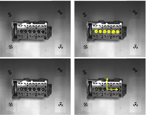
With the high-resolution stereo camera we take the next images of the combustion chambers machined surface. Because of the proper lighting conditions we achieve with the controllable lights the valve openings separate well from the plane and can easily be segmented. The proper valves are approximated by ellipses and the center is precisely measured. With the parameters of the stereo camera obtained during calibration we can compute the forward intersection providing us with the 3-D coordinates of the points. The two points define the origin and a direction of the coordinate system. The normal vector of the planar surface is measured with the LASCAM. This gives the missing third direction of the engine block’s internal coordinate system (see figure 5). The example above demonstrates well our approach to optical measurement using a coarse-to-fine strategy and is an excellent example of how different sensors can be combined to perform a measurement task.
Figure 5. Retrieving the objects internal coordinate system.
5.1. Registration and Data Fusion
The variety of sensors within our system implies that measurements differ in size, resolution and accuracy. For this reason, the integration of inhomogeneous datasets into one common surface description becomes a vital issue. Registration of 3-D data is performed using an extended iterative closest point algorithm (ICP),8 which directly works on triangular meshes. The vertices carry additional attributes like color and covariance information. Our implementation uses covariance information to choose appropriate weights for the point correspondences and hereby accounts for differences in the quality of the acquired data. The registration process is an iterative procedure, thus initial values are necessary to guarantee proper convergence. As the sensor orientation is known from the forward kinematic of the machine, good initial values can easily be provided.
In order to validate that a machined part meets its specification, the datasets can be registered against their CAD model and the deviation between the measured points and the CAD model is computed. Again, covariance information can be used to decide whether the observed deviation is significant or within the noise level.
6. SUMMARY
7. ACKNOWLEDGMENTS
The work presented in this paper was supported by the German Research Foundation under research grant DFG-SFB514. We wish to thank Daimler-Chrysler Corp. for providing us example parts.
Additional information on this project can be found on the world wide web at http://www.sfb514.uni-stuttgart.de
REFERENCES
1. The Common Object Request Broker: Architecture and Specification, Object Management Group, Inc., October 2000.
2. G. Kindermann, T. Buchheim, G. Hetzel, and P. Levi, “Ein multiagentensystem f¨ur explorative pr¨uftechnik,”
Informatik aktuell (GI), pp. 244–253, 1999.
3. C. Brenner, J. B¨ohm, and J. G¨uhring, “Photogrammetric calibration and accuracy evaluation of a cross-pattern stripe projector,”Proc. SPIE Videometrics VI 3641, pp. 164–172, January 1999.
4. N. Otsu, “A threshold selection method from grey-level histograms,”SMC 9, pp. 62–66, January 1979.
5. J. B¨ohm, C. Brenner, J. G¨uhring, and D. Fritsch, “Automated extraction of features from cad models for 3d object recognition,” inISPRS Congress 2000, vol. 33, (Amsterdam, Netherlands), 2000.
6. J. B¨ohm, C. Brenner, J. G¨uhring, and D. Fritsch, “Cad-basierte objekterkennung f¨ur ein multisensorielles meßsys-tem,” Mustererkennung 1999, pp. 62–69, 1999.
7. C. Brenner, J. B¨ohm, and J. G¨uhring, “Experimental measurement system for industrial inspection of 3d parts,”