International Journal of Nanomedicine
Generation of THz frequency using PANDA ring
resonator for THz imaging
MA Jalil1
Afroozeh Abdolkarim2
T Saktioto2
CT Ong3
Preecha P Yupapin4
1Ibnu Sina Institute of Fundamental Science Studies, Nanotechnology Research Alliance, Universiti Teknologi Malaysia (UTM),81310, Johor Bahru, Malaysia; 2Institute of Advanced Photonics Science, Nanotechnology Research Alliance, Universiti Teknologi Malaysia (UTM), 81310, Johor Bahru, Malaysia; 3Department of Mathematics, Universiti Teknologi Malaysia 81310 Skudai, Johor Bahru, Malaysia; 4Nanoscale Science and Engineering Research Alliance (N’SERA), Advanced Research Center for Photonics, Faculty of Science, King Mongkut’s Institute of Technology Ladkrabang, Bangkok 10520, Thailand
Correspondence: PP Yupapin Nanoscale Science and Engineering Research Alliance (N’SERA), Advanced Research Center for Photonics, Faculty of Science, King Mongkut’s Institute of Technology Ladkrabang, Bangkok 10520, Thailand
Tel +66 2 329 8414 Fax +66 2 329 8410
Email [email protected]; isoqt@kmitl. ac.th
Abstract: In this study, we have generated terahertz (THz) frequency by a novel design of microring resonators for medical applications. The dense wavelength-division multiplexing can be generated and obtained by using a Gaussian pulse propagating within a modified PANDA ring resonator and an add/drop filter system. Our results show that the THz frequency region can be obtained between 40–50 THz. This area of frequency provides a reliable frequency band for THz pulsed imaging.
Keywords: THz imaging, THz technology, MRRs, PANDA, add/drop filter
Introduction
Nonlinear terahertz (THz) radiation is the electromagnetic spectrum which ranges from 30 THz to 100 GHz. It covers the region away from microwaves via mid to beyond infrared. Formerly, bulky and expensive equipment such as free electron lasers or the alternative employment of thermal sources produced weak, incoherent radiation. THz radiation gives rise to rotational and vibrating excitation of some biological molecules. THz radiation has also been used in tissue with differentiating abilities.1
There is an increasing tendency towards THz technology for the next wave of
nonin-vasive biomedical instruments.2,3 THz pulse has many properties that could
encour-age the use of THz pulsed imaging (TPI) as a medical imaging tool. Moreover, THz waves are useful for the analysis of histopathological diagnosis, without any staining
process.4 Rayleigh scattering of electromagnetic radiation increases with the inverse
of the wavelength to the fourth power. However, there is no ionization hazard for
bio-logical tissue.5 TPI is a new technique based on broadband pulses of electromagnetic
radiation of THz frequencies.6,7 Contrast images can be obtained for different degrees
of THz wave absorption for normal tissues, such as muscles, fatty tissue and carti-lage, as well as cancer tissue. We can obtain THz images using a microring resonator
(MRR) in a wide range of wavelengths.8,9 The THz pulse interacts with the sample
in reflection or transmission modes. The modified pulse is recorded as a time-series. The spectra information from THz pulses has been used to distinguish different types of soft tissues, such as muscle, fat, and kidney tissues.10,11
Methodology and results
In order to achieve a wide band frequency carrier, we propose a novel system consist-ing of MRRs for many communication applications such as a wireless THz
commu-nication system and faster data transfer, which requires higher carrier frequencies.12
Dove
press
O R I G I N A L R E S E A R C H
open access to scientific and medical research
Open Access Full Text Article
International Journal of Nanomedicine downloaded from https://www.dovepress.com/ by 118.70.13.36 on 23-Aug-2020
For personal use only.
Number of times this article has been viewed
This article was published in the following Dove Press journal: International Journal of Nanomedicine
In this paper, we use MRRs made of InGaAsP/InP material to enhance the channels of the frequency band for implementa-tion in medical imaging.13
The transfer function of the system uses Gaussian beam,
described by Equation 1.14
Ei1=A1exp(iω0t) (1)
Here A1 is the amplitude of the optical field and t is the time for phase shift with frequency shift of ω0. The optical
outputs from the first and second ring resonators are given by Equations 2 and 3.15,16
Eout Ei L jK Ln
1 1
1 1 1 1
1
1 1 1 1 2
1 1 1
= - - -
-- -
-κ γ γ α
κ γ
)( ) ( ) exp(( ) )
( )(
/
11) exp((- 12)- 1)
αL jK L
n
/
Ei Eout L jK L
n
2 1
2 2 2 2 2
2
1 1 1 2
1 1 1
= − − − − − −
− − −
κ γ γ α
κ γ
)( ) ( ) exp(( ) )
( )(
/
22) exp(( 2 2) 2)
. − −
αL/ jK Ln
(3)
Here κ is the coupling coefficient, and K represents the wave number in vacuum. γ is the fractional coupling intensity loss. L1 and L2 are circumferences of the first and second rings. Exp(-αL/2) shows the roundtrip loss coefficient
and α is the waveguide loss. For the PANDA system, the
output optical fields from right and left rings are expressed by Equations 4 and 5.
ER =E - L - jK Ln - - - R
-1
5 5 5
8 4 1 1 1 2
exp(( α / ) ( / )) ( γ )( κ ) ( γ ) exp(( αL / ) jj
j
n R
R n R
K L
L K L
)
( )( ) exp(( ) )
1- 1- 5 1- 5 - 2
- γ κ α /
EL=E3exp((−αL/8) (− jK Ln /4)) (1−κ6)(1−γ6) (− −1 γ6) exp((−αLL/2)− jjK L
L jK L
n L
L n L
)
( )( ) exp(( ) ) .
1− 1− 6 1− 6 − 2 −
κ γ α /
Here, ER and EL are the outputs from the right and left rings of the PANDA system. The interior output fields of E1, E2, E3, and E4 are shown in Equations 6–9.
E j E
E E L jK L
i
R L n
1
3 3 2
3 4
1
1 1 1 2
= −
− − − − −
κ γ
κ κ α
( )( ) exp(( / ) (6)
E2=E E1 Rexp((−αL/4) (− jK Ln /2)) (7)
E3=E E1 R (1−κ4)(1−γ4) exp((−αL/4) (− jK Ln /2)) (8)
E4=E E EL 1 R (1−κ4)(1−γ4) exp((−αL/2)− jK Ln ). (9)
Therefore, the final equations for drop port and throughput power are given in Equations 10–13.
E E
j
E E E L
t i L R = − − + − − − − ×
2 3 3
3 3 4 4
1
1 1
1 1 1
2 ( )( ) ( ) ( )( ) exp(( ) κ γ κ γ κ γ
α / −− jK Ln ) (10)
Ed= j κ4(1−γ4)E E1 Rexp((−αL/4) (− jK Ln /2)) (11)
Pt=( ) ( )Et ⋅ Et *= Et2 (12)
Pd =(Ed) (⋅ Ed)*= Ed2. (13)
where Pt and Pd represent the output powers of the throughput and drop port, respectively.14,15
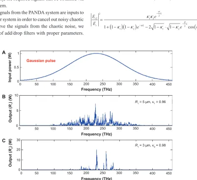
In this work we use a Gaussian beam as an input power to the proposed system. The new design of the system is illustrated in Figure 1. In this case the Gaussian pulse
with a center wavelength of 1.3 µm, pulse width of 20 ns,
and power of 1 W, is an input into the system as shown
in Figure 2A. The parameters used are R1= 5 µm (radius
of first ring), R2= 3 µm (radius of second ring), RL= 1
µm (radius of left ring of PANDA), RR= 1 µm (radius of
right ring of PANDA), R = 3 µm (radius of centered ring
of PANDA), Aeff= 0.10–0.25 µm.2 Some fixed parameters
such as nonlinear refractive index, n0 = 3.34 (InGaAsP/ InP)17 and intensity attenuation coefficient, α= 0.2 dBmm-1
have been selected for this system. The coupler intensity loss is γ = 0.1. The coupling coefficient of the MMR varies from 0.1–0.98. The nonlinear refractive index is n2= 2.2 × 10⁻¹⁷.
The input pulse is sliced to a smaller signal through the spectrum shown in Figure 2B and C. The light pulse can be chopped into discrete signals and amplified in the first ring, where more signal amplification is obtained by the second ring (smaller ring). The output signals from the (4)
(5) (2)
Dovepress
Jalil et al
International Journal of Nanomedicine downloaded from https://www.dovepress.com/ by 118.70.13.36 on 23-Aug-2020
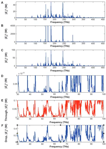
second ring resonator are inputs into the PANDA system. Output signals of the PANDA system are simulated and shown in Figure 3A–F. Figure 3E and F show the best region of frequency, which can be seen at the range of 40–50 THz. In practice, the channel frequency can be increased by using the system. Finally, the required signals can be obtained via the PANDA system.
The output signals from the PANDA system are inputs to the add/drop filter system in order to cancel out noisy chaotic signals. To retrieve the signals from the chaotic noise, we suggest the use of add/drop filters with proper parameters.
Two complementary optical circuits of the MRR add/drop filter can be illustrated by Equations 14 and 15.17
E E
e k L e
t
t
L
n
L 1
2
1 1 2
2
2
1
1 2 1 1 1
1 1 1
= − − − ⋅ − + −
+ − −
(
)
( ) (
)
(
)
− −
κ κ κ κ
κ
α
α
cos
κ
κ κ κ
α
α
2 1 2
2
2 1 1
(
)
e− L− − ⋅ − e− L( )
k Ln
cos
(14)
E E
e
e e k L
t
t
L
L L
n 2
2
1 2 2
1 2 1 2
2
1 1 1 2 1 1
=
+ − − − − ⋅ −
−
− −
(
)(
)
( )
κ κ
κ κ κ κ
α
α
α
cos ,,
(15)
Input port (Ei1)
R1
RR K 6
K3
K4 K5 R
PANDA
R2
K2
K1 E
i2
E4 E1
Et
E3 Ed
E2
Add (control) port
RL
Figure 1 Schematic of two microring resonators coupled into a PANDA system.
0 0 0.5 1
A
B
C
50 100 150
Input power (W)
Output
(R2
) (W)
Output
(R1
) (W)
200 250 300 350 400 450
0 0
0 5 10
30
20
10
50 100 150 200 250
Frequency (THz) Frequency (THz) Frequency (THz)
Gaussian pulse
300 350 400 450
R1 = 3 µm, κ2 = 0.98
R1 = 5 µm, κ1 = 0.96
0 50 100 150 200 250 300 350 400 450
Figure 2 Result of the outputs from two ring resonators with centre wavelength at 1.3 µm: (A) the input Gaussian pulse, (B) the chaotic signal generation, (C) the amplified
and filtering signals.
Dovepress THz frequency using PANDA
International Journal of Nanomedicine downloaded from https://www.dovepress.com/ by 118.70.13.36 on 23-Aug-2020
where Et1 and Et2 represent the optical fields of the throughput and drop port, respectively. β = kneff is the propagation constant, neff is the effective refractive index of the waveguide, L = 2πR is the circumference of the ring, and R is the radius of the ring. For simplification, we define
the phase constant as φ= βL. Chaotic noise cancellation
and required signals can be obtained by using the particular parameters of the add/drop device. κ1 and κ2 are coupling coefficients of the add/drop filters, κn = 2π/λ is the wave
propagation number for a vacuum, where the waveguide
40
A
B
C
D
E
F
20
0
100 0 2000 4000
50
0
0 50 100 150 200
Frequency (THz)
Frequency (THz)
Frequency (THz)
Frequency (THz)
Frequency (THz)
Frequency (THz)
250 300 350 400 450
0 50 100 150 200 250 300 350 400 450
0 50 100 150 200 250 300 350 400 450
30 0 1
0.05
0.1
0 0.05
0.4
0.2
0
40 50 60 70 80 90 100
30 40 50 60 70 80 90 100
30 40 50 60 70 80
|E3
|
2 (W)
|E4
|
2 (W)
|E2
|
2 (W)
|E1
|
2 (W)
90 100
Drop,
|Ed
|
2 (W)
Through,
|Et
|
2 (W
)
x 10–3
Figure 3 Simulation results of the light pulse generated by the PANDA system at center wavelength of 1.3 µm, where (A) |E1|2, (B) |E2|2, (C) |E3|2, (D) |E4|2, (E) |Ed|2, and (F) |Et|2 are output powers inside a PANDA system.
Et
Et2 K
2 Add/drop system
Et1 K1
Figure 4 Schematic of an add/drop filter system for area frequency selection.
Dovepress
Jalil et al
International Journal of Nanomedicine downloaded from https://www.dovepress.com/ by 118.70.13.36 on 23-Aug-2020
loss is α = 0.2 dB/mm. The fractional coupler intensity loss is γ = 0.1. For the add/drop filter device, the nonlinear
refractive index is neglected.
We used an add/drop filter system with a radius of 10 µm to determine the free spectral range, the number of channels and bandwidth as shown in Figure 4. Figure 5 shows the simulation results where Figure 5A and B represent the throughput and drop port outputs of the system, respectively.
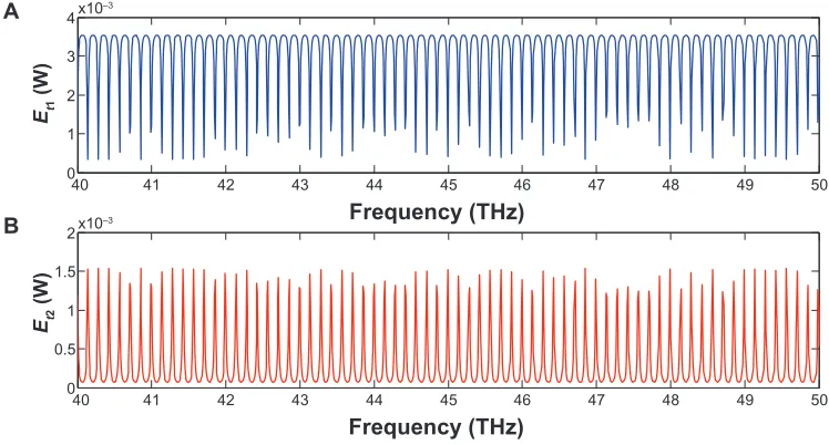
As demonstrated in Figure 6, generated dense wavelength-division multiplexing from the proposed configuration of ring resonators are involved in the THz region, which provides a reliable frequency band for medical applications, especially for THz imaging. The main advantage of THz imaging is
its diagnostic capabilities.11 These obtained pulses are also
useful for analysis of the histopathological diagnosis, without any staining process.6
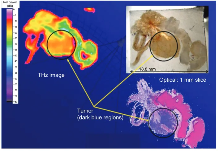
To date, imaging spectroscopy is used only for small areas.3,4 THz imaging exactly reflects the tissue situation, for
instance tumor, nontumor tissues, tissue degeneration, and fibrosis. The THz image shows significantly reduced absorp-tion of THz radiaabsorp-tion in this region compared with normal tissue, which suggests its usefulness for detecting tumors (Figure 7). Contrast images associated with different degrees of absorption of THz waves have been obtained for normal tissues, such as muscles, fatty tissue, and cartilage, as well as for cancer tissue. We could obtain THz images of large areas
from an MRR in a wide range of wavelengths.8,10,11
0
50 100 150 200 250 300 350 400 450
50 100 150 200 250 300 350 400 450
0.5
1 1.5 2 0
A
B 1
2 3 4x10–3
x10–3
Frequency (THz)
Et1
(W
)
Et2
(W
)
Frequency (THz)
Figure 5 Simulation results of the channel frequency light pulse generated by the add/drop filter system at the center wavelength of 1.3 µm for Gaussian pulse: (A) system
throughput, (B) system drop port.
40 41 42 43 44 45 46 47 48 49 50
0
A
B
1 2 3 4x10⁻³
Frequency (THz)
40 41 42 43 44 45 46 47 48 49 50
0 0.5 1 1.5
2x10⁻³
Frequency (THz)
Et1
(W
)
Et2
(W
)
Figure 6 Expansion of simulation result of the channel frequency light pulse generated by the add/drop filter system.
Dovepress THz frequency using PANDA
International Journal of Nanomedicine downloaded from https://www.dovepress.com/ by 118.70.13.36 on 23-Aug-2020
Conclusion
In this study, a new MRR design has been introduced, which provides the best frequency band when the input Gaussian pulse is used. This system consists of a series of MRRs connected to a PANDA system. Using the proposed system, multifrequency bands can be generated and simultaneously linked to an add/drop filter where it is suitable for analysis of the histopathological diagnosis. The results show the frequency band region lies between 40–50 THz. This range provides a reliable frequency band for medical purposes, especially in THz imaging.
Acknowledgments
We would like to thank the Institute of Advanced Photonics Science, Nanotechnology Research Alliance, Universiti Teknologi Malaysia (UTM) and King Mongkut’s Institute of Technology (KMITL), Thailand for providing the research facilities. This research work has been supported by SLAI IDF financial support from UTM. The authors report no conflicts of interest in this work.
References
1. Mittleman MD, Jacobson RH, Nuss MC. T-ray imaging. IEEE J Sel Top Quant Electron. 1996;2:679–692.
2. Iglesias EJ, Smith AW, Kaplan SG. A sensitive, spatially uniform photo-detector for broadband infrared spectrophotometry. Appl Opt. 2008;47: 2430–2436.
3. Arnone D, Ciesla C, Pepper M. Terahertz imaging comes into view. Phys World. 2000;13:35–40.
4. Knobloch P, Schildknecht C, Kleine-Ostmann T, et al. Medical THz imaging: An investigation of histo-pathological samples. Phys Med Biol. 2002;47:3875–3884.
5. Fitzgerald A, Berry E, Zinovev N, Walker GC, Smith MA, Chamberlain JM. An introduction to medical imaging with coherent terahertz frequency radiation. Phys Med Biol. 2002;47: R67–R84.
6. Hu B, Nuss M. Imaging with terahertz waves. Opt Lett. 1995;20: 1716–1718.
7. Zhang X. Generation and detection of pulsed microwave signals by THz optoelectronics. Proceedings of 1997 SBMO/IEEE MTT-S International Microwave and Optoelectronics Conference, 1997. Linking to the Next Century. Natal, Brazil. August 11–14, 1997;1: 215–220.
8. Nishizawa JI, Sasaki T, Suto K, et al. THz imaging of nucleobases and cancerous tissue using a GaP THz-wave generator. Opt Comm. 2005; 244(1–6):469–474.
9. Wallace VP, Taday PF, Fitzgerald AJ, et al. Terahertz pulsed imaging and spectroscopy for biomedical and pharmaceutical applications. Faraday Discuss. 2004;126:255–263.
10. Fitzgerald AJ, Wallace VP, Jimenez-Linan ML, et al. Terahertz pulsed imaging of human breast tumors. Radiology. 2006;239: 533–540.
11. Nakajima S, Hoshina H, Yamashita M, Otani C, Miyoshi N. Terahertz imaging diagnostics of cancer tissues with a chemometrics technique. Appl Phys Lett. 2007;90:041102.
12. Udomariyasap P, Noppanakeepong S, Mitatha S, Yupapin PP. THz light pulse generation and storage within an embedded optical waveguide system. J Nonlinear Opt Phys. 2010;19:303–310.
13. Grover R, Absil PP, Van V, et al. Vertically coupled GaInAsP-InP micror-ing resonators. Opt Lett. 2001;26:506–508.
14. Juleang P, Phongsanam P, Mitatha S, Yupapin PP. Public key suppres-sion and recovery using a PANDA ring resonator for high security communication. Opt Eng. 2011;50:035002.
THz image Rel power
(dB)
−5 0
−10 −15 −20 −25
18.8 mm −30
−35 −40 −45 −50 −55 −60 −65 −70
−80 −75
Tumor
(dark blue regions)
Optical: 1 mm slice
Figure 7 Prostate section with tumor tissue as imaged with terahertz, optical, and staining techniques.
Dovepress
Jalil et al
International Journal of Nanomedicine downloaded from https://www.dovepress.com/ by 118.70.13.36 on 23-Aug-2020
International Journal of Nanomedicine
Publish your work in this journal
Submit your manuscript here: http://www.dovepress.com/international-journal-of-nanomedicine-journal The International Journal of Nanomedicine is an international,
peer-reviewed journal focusing on the application of nanotechnology in diagnostics, therapeutics, and drug delivery systems throughout the biomedical field. This journal is indexed on PubMed Central, MedLine, CAS, SciSearch®, Current Contents®/Clinical Medicine,
Journal Citation Reports/Science Edition, EMBase, Scopus and the Elsevier Bibliographic databases. The manuscript management system is completely online and includes a very quick and fair peer-review system, which is all easy to use. Visit http://www.dovepress.com/ testimonials.php to read real quotes from published authors. 15. Yupapin PP, Vanishkorn B. Mathematical simulation of light pulse
propagating within a microring resonator system and applications. Appl Math Model. 2011;35:1729–1738.
16. Amiri IS, Afroozeh A, Bahadoran M. Simulation and analysis of multisoliton generation using a PANDA ring resonator system. Chinese Phys Lett. 2011;28:104205.
17. Piyatamrong B, Kulsirirat K, Techitdheera W, Mitatha S, Yupapin PP. Dynamic potential well generation and control using double resonators incorporating an add/drop filter. Mod Phys Lett B. 2010;24:3071–3080. Dovepress
Dove
press
THz frequency using PANDA
International Journal of Nanomedicine downloaded from https://www.dovepress.com/ by 118.70.13.36 on 23-Aug-2020