ISSN (Print) : 2320 – 3765 ISSN (Online): 2278 – 8875
I
nternational
J
ournal of
A
dvanced
R
esearch in
E
lectrical,
E
lectronics and
I
nstrumentation
E
ngineering
(An ISO 3297: 2007 Certified Organization)
Vol. 5, Issue 11, November 2016
Performance Comparison of BL-CSC
Converter Fed Four Switch BLDC Motor with
Power Factor Correction
Akshatha R Hegde1, T.Meenakshi2, Arun Kumar N3
PG Scholar, Dept of EEE, Jansons Institute of Technology, Coimbatore, India1
Assistant Professor, Dept of EEE, Jansons Institute of Technology, Coimbatore, India 2
Lecturer, Dept of EEE, MVJ Polytechnic, Bangalore, India 3
ABSTRACT: Brushless dc motors have been widely used in industrial automation and consumer appliances because of their higher efficiency and power density. BLDC motor has permanent magnets in rotor assembly to generate steady state magnetic field, due to this it is advantageous compared to induction motors. This paper presents a power factor correction (PFC) based bridgeless-canonical switching cell (BL-CSC) converter fed brushless DC (BLDC) motor drive. The proposed BL-CSC converter operating in a discontinuous inductor current mode is used to achieve a unity power factor at the AC mains using a single voltage sensor. The speed of BLDC motor is controlled by varying the DC bus voltage of the voltage source inverter (VSI) feeding four switch BLDC motor via a PFC converter. It is an adequate try on reducing the cost. Therefore, the BLDC motor is electronically commutated such that the VSI operates in fundamental frequency switching for reduced switching losses. Moreover, the bridgeless configuration of CSC converter offers low conduction losses due to partial elimination of diode bridge rectifier at the front end. The proposed configuration shows a considerable increase in efficiency as compared to the conventional scheme. The performance of the proposed drive is validated through experimental results obtained on a developed prototype.
KEY WORDS: BLDC Motor, BL-CSC Converter, DICM, PFC, Power Quality.
I.INTRODUCTION
BLDC motor is a synchronous motor with permanent magnets in rotor having electronic commutation. It takes dc supply which is converted to ac by the electronic commutator and the three phase supply is fed to the motor. The BLDC motor employs six switches for the commutation. It is mainly used for the application with variable speed.This has gained a lot of importance as it has tremendous advantages such as the absence of sparking, noise, Electro Magnetic Interference and has low maintenance due to the absent of brushes. The current trend of employing BLDC motor includes only four switches reducing the switching losses. The speed can be controlled to the expected range or value. This is achieved by either employing sensors or sensorless control to commute the switches. The sensors employed here could be a hall effect element or a optical sensor which proceeds the electronic commutation based on the rotor position. The sensorless control will sense the phase voltages and currents and determines the position of the rotor.
At the front end, the Diode Bridge Rectifier converts ac to dc. But the DBR induces harmonics in the supply. Hence the Power Factor Correction converters are employed to improve the power quality in AC mains.The PFC converters could be with or without isolation. The PFC consists of less number of components and hence it has reduced switching losses. The continuous mode of conduction offers low stress on the converter but requires three sensors. A single sensor is required in case of discontinuous mode of conduction but it allows high stress on the PFC converter.
ISSN (Print) : 2320 – 3765 ISSN (Online): 2278 – 8875
I
nternational
J
ournal of
A
dvanced
R
esearch in
E
lectrical,
E
lectronics and
I
nstrumentation
E
ngineering
(An ISO 3297: 2007 Certified Organization)
Vol. 5, Issue 11, November 2016
voltage control. The BL-CSC converters consist of bridge as shown in fig. 1 but the bridgeless PFC converters offer low conduction losses at the front end. Conventional Buck-Boost PFC converter makes use of three switches increasing the switching losses. Bridgeless Buck-Boost PFC converter employs two switch reducing the switching losses compared to the conventional Buck-Boost PFC converter. The higher order PFC Bridgeless CUK, SEPIC, ZETA are been widely used. But when compared to CSC Converter they have more number of components. CSC converter has an excellent performance as a power factor pre-regulator for a low power application.
Fig. 1 CSC converter
The proposed BL-CSC converter based VSI fed four switch BLDC motor drive is as depicted in the fig. 2. The diode bridge rectifier is eliminated hence named bridgeless which reduces the conduction losses associated with it. The BL-CSC is designed in such a way that it operates in discontinuous inductor current mode. VC1 and VC2 remainscontinuous during the switching period. BL-CSC converter provides variable DC link voltage for controlling the speed of the BLDC motor. The BLDC motor is electronically commutated for reduced switching losses in VSI. The CSC converter in the figure a. consists of the diode bridge rectifier. Hence the number of components used in the BL-CSC converter is less and has low losses when compared to BUCK-BOOST, CUK, SEPIC, ZETA converters.
Fig. 2 Proposed BL-CSC converter
ISSN (Print) : 2320 – 3765 ISSN (Online): 2278 – 8875
I
nternational
J
ournal of
A
dvanced
R
esearch in
E
lectrical,
E
lectronics and
I
nstrumentation
E
ngineering
(An ISO 3297: 2007 Certified Organization)
Vol. 5, Issue 11, November 2016
turned on during the half period conduction irrespective of the range of voltages which is not possible in Buck or Boost converter. Hence the stress on the switches and hence switching losses will be reduced.
Configuration No. of Devices Half period
conduction
SW D L C Total
BL-Buck[20] 2 4 2 2 10 5
BL-Boost[21] 2 2 1 1 6 4
BL-Boost[22] 2 2 1 2 7 7
BL-Buck-Boost[23] 3 4 1 3 11 8
BL-Buck-Boost[24] 2 4 2 1 9 5
BL-Cuk-T-1[25] 2 3 3 3 11 7
BL-Cuk-T-2[25] 2 2 3 4 11 11
BL-Cuk-T-3[25,26] 2 4 4 3 13 7
BL-Cuk[27] 2 3 3 2 10 8
BL-SEPIC[28] 2 3 1 3 9 7
BL-SEPIC[29] 2 3 2 2 9 7
BL-ZETA[30] 2 4 4 3 13 7
Proposed BL-CSC 2 4 2 3 11 6
Table 1Switches conducting during half period conduction for different configuration
The four switch BLDC motor is as shown in the fig. 3. The sequence of the energisation of the phase with the conducting devices is shown in the table2.
Fig. 3 Four switch BLDC motor
ISSN (Print) : 2320 – 3765 ISSN (Online): 2278 – 8875
I
nternational
J
ournal of
A
dvanced
R
esearch in
E
lectrical,
E
lectronics and
I
nstrumentation
E
ngineering
(An ISO 3297: 2007 Certified Organization)
Vol. 5, Issue 11, November 2016
Mode Hall
values
Working phase Conducting devices
Mode 1 101 +a, -b S1, S4
Mode 2 100 +a, -c S1
Mode 3 110 +b, -c S3
Mode 4 010 +b, -a S2, S3
Mode 5 011 +c, -a S2
Mode 6 011 +c, -b S4
Table2 Sequence of switches to be turned on
The proposed BL-CSC converter fed four switch BLDC motor drive is depicted in the fig. 4. The capacitors C3 and C4 are made equal in order to balance the currents in the phases of the BLDC motor.
ISSN (Print) : 2320 – 3765 ISSN (Online): 2278 – 8875
I
nternational
J
ournal of
A
dvanced
R
esearch in
E
lectrical,
E
lectronics and
I
nstrumentation
E
ngineering
(An ISO 3297: 2007 Certified Organization)
Vol. 5, Issue 11, November 2016
II. SIMULATION AND RESULTS
The MATLAB Simulation is done considering the bridge rectifier converter with the Power Factor Correction at the supply as shown in fig. 5.
. Fig. 5 Simulation of bridge rectifier as converter
The Fig. a shows the input and output voltages and currents when bridge rectifier is employed where the input voltage and currents are not in phase but close to unity.
Fig. a Input and output voltages and currents
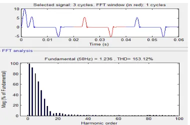
Fig. b is the FFT Analysis of the input current. The power quality is poor at the input supply.
ISSN (Print) : 2320 – 3765 ISSN (Online): 2278 – 8875
I
nternational
J
ournal of
A
dvanced
R
esearch in
E
lectrical,
E
lectronics and
I
nstrumentation
E
ngineering
(An ISO 3297: 2007 Certified Organization)
Vol. 5, Issue 11, November 2016
Now let us consider the BL-CSC converter as shown in the fig. 5 for which the comparison is made with the simulation results.
Fig. 5 BL-CSC converter
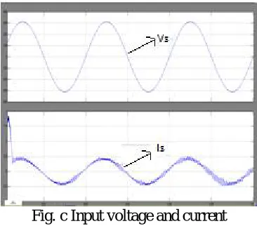
The Fig. c shows the input voltage and current waveform of the proposed converter. It can be observed from the waveform that the voltage and current is almost in phase and also has better power factor when compared to the bridge rectifier.
Fig. c Input voltage and current
ISSN (Print) : 2320 – 3765 ISSN (Online): 2278 – 8875
I
nternational
J
ournal of
A
dvanced
R
esearch in
E
lectrical,
E
lectronics and
I
nstrumentation
E
ngineering
(An ISO 3297: 2007 Certified Organization)
Vol. 5, Issue 11, November 2016
Fig. d Output dc voltage
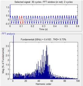
Fig e is the FFT analysis of the BL-CSC converter where it can be seen that except fundamental harmonics, all others are less than 3.5 reducing the harmonics which inturn improves the power quality of the system.
Fig. e Harmonics in the input current
III. CONCLUSION
ISSN (Print) : 2320 – 3765 ISSN (Online): 2278 – 8875
I
nternational
J
ournal of
A
dvanced
R
esearch in
E
lectrical,
E
lectronics and
I
nstrumentation
E
ngineering
(An ISO 3297: 2007 Certified Organization)
Vol. 5, Issue 11, November 2016
improved by employing the BL-CSC converter. This has a lot of scope in the power electronics in renewable energy sources.
REFERENCES
[1] M PetreenaMonisha and G Nirmal, “A Simple Position Sensoreless Control Strategy Of Four Switch Three Phase Brushless Dc Motor
Drives Using Single Current Sensor”, International Journal of Advanced Trends in Computer Science and Engineering, Vol.2, No.2, pp.255-260, 2013
[2] P.Rajasekaran,K.Vanchinathan , “Improved Performance of Four Switch Three Phase Brushless DC Motor using Speed-Current Control
Algorithm”, International Journal of Computer Applications, Vol. 68-No.11, pp.0975 – 8887, 2013
[3] Jibin M Varghese , Jaya B and Justin Baby, “ PI tuning control of Four Switch Three Phase Brushless DC Motor”, International Conference
on Signal, Image Processing and Applications With workshop of ICEEA, vol.21, pp.260-264, 2011
[4] A.Elakya, M.Vinaya, G.S.Arun Kumar, “Efficient Cost Reduction in BLDC Motor Using Four Switch Inverter and PID Controller” ,
International Journal of Advanced Research in Electrical, Electronics and Instrumentation Engineering , Vol. 3, Issue 2, pp.7294-73022014
[5] S. Sathish Kumar and R. Meenakumari, “Design and Implementation of Low Cost Four Switch Inverter for BLDC Motor Drive with Active
Power Factor Correction”, Middle-East Journal of Scientific Research, Vol. 21, Issue 12, pp.2352-2358, 2014
[6] Bhim Singh and VashistBist,“A BL-CSC Converter Fed BLDC Motor Drive with Power Factor Correction”,
IEEE Transactions on Industrial Electronics, Vol. 62, Issue 1,pp.172-183, 2014
[7] Shanmugam, S.K., Ramachandran, M., Kanagaraj, K.K. and Loganathan,“ Sensorless Control of Four-Switch Inverter for Brushless DC
Motor Drive and Its Simulation”Circuits and Systems,Vol.7, Issue 6, pp.726-734,2016
[8] Sathish Kumar Shanmugam, MeenakumariRamachandran, Krishna Kumar Kanagaraj, AnbarasuLoganathan , “Sensorless Control of
Four-Switch Inverter for Brushless DC Motor Drive and Its Simulation", Circuits and Systems, Vol.7, pp.726-734, 2016
[9] PriyaJanak, RanvirKaur and Fatehgarh Sahib, “Effect of Harmonics on the Performance Characteristics of Three Phase Squirrel Cage
Induction Motor”, International Journal Of Research In Electronics And Computer Engineering, Vol. 2, Issue 2, pp. 77-89, 2014
[10] Hani Vahedi, Kamal Al-Haddad, Youssef Ounejjar, “Crossover Switches Cell (CSC): A New Multilevel Inverter Topology with Maximum
Voltage Levels and Minimum DC Sources “, Research Gate, Vol.8, Issue13, pp.54-59, 2013
[11] “Low-Cost Sensorless Control of Brushless dc Motors with Improved Speed Range”, Gui-Jia Su and John W. McKeever Oak Ridge National