Available online: https://edupediapublications.org/journals/index.php/IJR/ P a g e | 1120
Embedding 2d Barcode By Using Aztec Barcode
1
P.Sree Rekha,
2V.Rama Rao,
1
M-Tech(DECS), Department of Electronics & Communication Engineering, Eluru College
of Engineering & Technology, Eluru, AP, India
2
Associate professor, Department of Electronics & Communication Engineering, Eluru
College of Engineering & Technology, Eluru, AP, India
ABSTRACT
Nowadays, 2D barcodes have been widely used as an interface to connect potential
customers and advertisement contents. PiCode is designed with careful considerations on
both the perceptual quality of the embedded image and the decoding robustness of the
encoded message. Comparisons with the existing beautified 2D barcodes Aztec code
achieves one of the best perceptual qualities for the embedded image, and maintains a better
tradeoff between image quality and decoding robustness in various application conditions.
Aztec code has been implemented in the MATLAB on a PC and some key building blocks
have also been ported to Android and iOS platforms. Its practicality for real-world
applications has been successfully demonstrated
.Keywords: Quick Response (QR) Codes, Half Toning, Ordered Dithering, Gray Scale Image, Binary Image
I INTRODUCTION
A QR code is a 2D barcode that can encode information like numbers, letters and binary codes.
Available online: https://edupediapublications.org/journals/index.php/IJR/ P a g e | 1121 PiCode is a new form of the 2D barcodes. It aims to show not only machine-readable data, but also show human-recognisable visual information or a picture, such as a company logo, a cartoon, a low resolution photo, etc. Since anyone scanning a barcode with his/her mobile phone must also look at it for seconds during the camera focusing process, it is a perfect opportunity to advertise the brand logo of a company or show a picture related to the promoted product[6]. The existing 2D barcodes, such as Quick Response (QR) codes, is being usedfor this purpose by overwriting a central region of the barcode by a small picture. However, since the size of the overwritten region is limited by the error correlation capability and the size of the barcode in use, the embedded picture is typically too small to preserve the (brand) image quality of the (company logo) picture[7]. The Pi Code technology improves the aesthetic value of the picture embedded barcode by allowing the picture to be overlaid on almost the whole barcode area.
Function Pattern Region
This region contains all the necessary information to successfully detect and sample the
information bits of the code. Finder and alignment patterns are the most essential modules in the
region and are key to locate, rotate and align the QR code as well as to correct for deformations in the
printing surface. In addition to finder and alignment patterns, timing patterns also aid in the
determination of the sampling grid especially for large code sizes.
2.1.1 Finder Pattern
Finder patterns are easily identifiable as three concentric square structures in the corners of the
code. They are designed to have the same ratio of black and white pixels when intersected by a line at
any angle, allowing determining its centre even if the code is scanned at arbitrary angles[8]. Finder
patterns are surrounded by two guard zones of one QR 10 module wide called the separators. These
zones aid in the separation of finder patterns from the encoding region and in the identification of the
proper sequence of black and white pixels further improving the location accuracy.
Available online: https://edupediapublications.org/journals/index.php/IJR/ P a g e | 1122
2.1.2 Separators
The white separators have a width of one pixel and improve the recognisability of the finder patters as they separate them from the actual data[9].
2.1.3 Error Correction
Similar to the data section, error correction codes are stored in 8 bits long code words in the error correction section.
2.1.4 Alignment Patterns
Alignment patterns on the other hand are used to determine the sampling grids from which code
words are extracted and to correct for possible deformation of the printing surface.
2.1.5 Timing Patterns
The standard also defines two zones consisting on one row and one column of alternating black
and white QR modules, denoted as the timing zones and located between finder patterns.
2.2 Encoding Region
The code area delimited by finder patterns is denoted as the encoding region. where data, parity
modules and decoding information is stored. This area is divided into code words consisting of blocks
of 8 QR modules[10]. Two dimensional shapes of these code words depend on the version of the code
and are designed to optimize area coverage.
INFORMATION HIDING USING QR CODE
Available online: https://edupediapublications.org/journals/index.php/IJR/ P a g e | 1123
Fig 2. Architecture of information hiding using QR codes
The original message is divided, to form a string of characters into smaller parts, where smaller part is the number of QR code pattern that can be formed by a string of characters. The data in each part is encoded into ordinary QR code corresponding to that part of data[11]. The architecture of information hiding using QR code is shown in Fig 2.
At the receiving end, this QR code with special symbols is decoded to give back the number of QR code patterns that was encoded. After that, when this QR code with special symbols is scanned or read by optical device such as a scanner or a camera phone, the picture image can be analyzed. Using this picture image original information can be read and the decode the information from single QR code with special symbols and split the data back to their QR code pattern where these QR code pattern can be read by ordinary QR code reader[12]. The data in each QR code pattern were recognized and concatenated back to form its original information.
PREVIOUS WORK :
PI CODE:
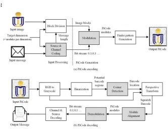
Fig-3 pi code encoding and decoding
Available online: https://edupediapublications.org/journals/index.php/IJR/ P a g e | 1124 Channel Coding - Code data for transmission over a noisy communication channel. PiCode generation part image blocks of k * k pixels are modified using adaptive modulation scheme.
PiCode decoding process contains key three steps coarse fine corner detection, module alignment and demodulation will be described. The corner detection algorithm locates four extreme corners of the barcode from the captured image. To achieve higher accuracy, the proposed coarse-fine corner detection scheme exploits[14] the prior information of the barcode structure in refining the corner locations. The module alignment step slices the barcode region into image blocks with reference to the black and white alternations in the shape pattern. Demodulation scheme will be used to retrieve the data bit resulted from module alignment step. Three demodulation schemes are proposed: contrast-based demodulation[15], matched filter-based operation, gradient-based operation. In the proposed work the decoding performance comparison is evaluated in terms of demodulation bit error probability (BEP) for three demodulation techniques
PROPOSED WORK
Aztec code:
The compact Aztec code core may be surrounded by 1 to 4 layers, producing symbols from 15×15 (room for 13 digits or 12 letters) through 27×27. There is additionally a special 11×11 "rune" that encodes one byte of information. The full core supports up to 32 layers, 151×151 pixels, which can encode 3832 digits, 3067 letters, or 1914 bytes of data. In fig Whatever part of the symbol is not used for the basic data is used for Reed–Solomon error correction, and the split is completely configurable, between limits of 1 data word, and 3 check words. The recommended number of check words is 23% of symbol capacity plus 3 codewords[16]. Aztec Code is supposed to produce readable codes with various printer technologies. It is also well suited for displays of cell phones and other mobile devices.
The symbol is built on a square grid with a bulls-eye pattern at its centre for locating the code. Data is encoded in concentric square rings around the bulls-eye pattern. The central bulls-eye is 9×9 or 13×13 pixels, and one row of pixels around that encodes basic coding parameters, producing a "core" of 11×11 or 15×15 squares. Data is added in "layers", each one containing two rings of pixels, giving total sizes of 15×15, 19×19, 23×23, etc.
Available online: https://edupediapublications.org/journals/index.php/IJR/ P a g e | 1125
Fig-4 Aztec code basic operation
FIG-5 Previous Method of PI-code FIG-6 Proposed Method of Aztec code
The core of the compact Aztec code (red ascending diagonal hatching), showing the central bulls-eye, the four orientation marks (blue diagonal cross-hatching), and space for 28 bits (7 bits per side) of coding information (green horizontal hatching). The first ring of data begins outside that (grey descending diagonal hatching) show in fig-5. The core of the full Aztec code. 40 bits are available between the orientation marks for encoding parameters Show in fig-6
CONCLUSION
This paper has designed a novel picturesque 2D barcode, named the Aztec code. Comparing with existing beautified PI codes, it provides one of the best perceptual quality in preserving the aesthetic appearance of the embedded image, while maintains the decoding robustness. It is achieved by the design of barcode pattern and better decoding algorithms. The Aztec code is designed with less obtrusive fixed patterns to avoid distortions on the embedded image, and a modulation scheme
Available online: https://edupediapublications.org/journals/index.php/IJR/ P a g e | 1126 some key steps of the decoding process have also been developed to guarantee the decoding robustness including the coarse-fine corner detection, module alignment with barcode structural information and demodulation with information from all pixels in each module.
Comparisons with the existing beautified PI codes by experimental results show that Aztec code has maintained a better trade-off between the perceptual quality and the decoding robustness (or normalized data capacity).
To evaluate its practicality, the Aztec code system has been implemented in Matlab on a PC, and as mobile application softwares in Android and iOS platforms. The perceptual quality and the decoding robustness of the Aztec code system have been successfully demonstrated. In the future, the unobtrusive pilot symbols will be embedded into the Aztec code center to serve as center alignment pattern and training symbols for the camera response function.
REFERENCES
[1] W. Huang and W. H. Mow, “PiCode: 2D barcode with embedded picture and ViCode: 3D barcode with embedded video,” in Proc. Int. Conf. Mobile Comput. Netw., 2013, pp. 139–141.
[2] C. Chen and W. H. Mow, “Poster: A coarse-fine corner detection approach for two-dimensional barcode decoding,” in Proc. Int. Conf. Mobile Comput. Netw., 2014, pp. 351–354.
[3] E. Ohbuchi, H. Hanaizumi, and L. A. Hock, “Barcode readers using the camera device in mobile phones,” in Proc. Int. Conf. Cyberworlds, Nov. 2004, pp. 260–265.
[4] J.M. McCune, A. Perrig, and M. K. Reiter, “Seeing-is-believing: Using camera phones for human-verifiable authentication,” in Proc. IEEE Symp. Secur. Privacy, May 2005, pp. 110–124.
[5] T.-Y. Liu, T.-H. Tan, and Y.-L. Chu, “2D barcode and augmented reality supported english earning system,” in Proc. Int. Conf. Comput. Inf. Sci.,Jul. 2007, pp. 5–10.
[6] J. Z. Gao, L. Prakash, and R. Jagatesan, “Understanding 2D-barcode technology and applications in M-commerce—Design and implementation of a 2D barcode processing solution,” in Proc. 31st Int.
Comput. Softw. Appl. Conf., vol. 2. Jul. 2007, pp. 49–56.
[7] Information Technology—Automatic Identification and Data Capture Techniques—QR Code 2005
Bar Code Symbology Specification, document ISO/IEC 16022, 2005.
[8] O2O Startup Visualead Secures Investment From Alibaba Group, accessed on Jun. 1, 2016.
[Online].
Available online: https://edupediapublications.org/journals/index.php/IJR/ P a g e | 1127 [10] H. Kato and K. T. Tan, “2D barcodes for mobile phones,” in Proc. 2nd Int. Conf. Mobile Technol., Appl., Syst., Nov. 2005, p. 8.
[11] H.-K. Chu, C.-S. Chang, R.-R. Lee, and N. J. Mitra, “Halftone QR codes,” ACM Trans. Graph., vol. 32, no. 6, pp. 217:1–217:8, Nov. 2013.
[12] G. J. Garateguy, G. R. Arce, D. L. Lau, and O. P. Villarreal, “QR images: Optimized image embedding in QR codes,” IEEE Trans. Image Process., vol. 23, no. 7, pp. 2842–2853, Jul. 2014.
[13] S. Ono, K. Morinaga, and S. Nakayama, “Two-dimensional barcode decoration based on real-coded genetic algorithm,” in Proc. IEEE Congr. Evol. Comput., Jun. 2008, pp. 1068–1073.
[14] D. Samretwit and T. Wakahara, “Measurement of reading characteristics of multiplexed image in QR code,” in Proc. 3rd Int. Conf. Intell. Netw. Collaborative Syst. (INCoS), Nov./Dec. 2011, pp. 552– 557.
[15] T.Wakahara and N. Yamamoto, “Image processing of 2-dimensional barcode,” in Proc. 14th Int.
Conf. Netw.-Based Inf. Syst. (NBiS), Sep. 2011, pp. 484–490.
[16] Y.-H. Lin, Y.-P. Chang, and J.-L. Wu, “Appearance-based QR code beautifier,” IEEE Trans.