International Journal of Research in Advent Technology, Special Issue, March 2019
E-ISSN: 2321-9637
3rd National Conference on Recent Trends & Innovations In Mechanical Engineering 15th & 16th March 2019
Available online at www.ijrat.org
16
Structural And Modal Analysis Of Two Wheeler Shock
Absorber
Department of ME, GPREC, Kurnool,
2
Department of ME, NNRG, Hyderabad
Abstract
A shock absorber is a mechanical device designed
to smooth out or damp shock impulse, and dissipate kinetic energy. In a vehicle, it reduces the effect of traveling over rough ground, leading to improve ride quality, and increase in comfort due to substantially reduced amplitude of disturbances. When a vehicle is traveling on a level road and the wheels strike a bump, the spring is compressed quickly. The compressed spring will attempt to return to its normal loaded length and, in so doing, will rebound past its normal height, causing the body to be lifted. The weight of the handling of the vehicle very difficult.The design of spring in shock absorber is very important. In this project a shock absorber is designed and a 3D model is created using Creo. Structural analysis and modal analysis are done on the shock absorber using ANSYS software by varying material for spring (i.e.) carbon steel and beryllium copper and phosphor bronze. Structural analysis is done to validate the strength and modal analysis is done to determine the displacements for different frequencies for number of modes. After getting results from analysis comparison is done for any two quality, and increase in comfort due to substantially reduced amplitude of disturbances. Without shock absorbers, the vehicle would have a bouncing ride, as energy is stored in the spring and then released to the vehicle, possibly exceeding the allowed range of suspension movement. Control of excessive suspension movement without shock absorption requires stiffer (higher rate) springs, which would in turn give a harsh ride. Shock absorbers allow the use of soft (lower rate) springs while controlling the rate of suspension movement in response to bumps. They also, along with hysteresis in the tire itself, damp the motion of the unsprung weight up and down on the springiness of the tire. Since the tire is not as soft as the springs, effective wheel bounce damping may require stiffer shocks than
would be ideal for the vehicle motion alone. Spring-based shock absorbers commonly use coil springs or leaf springs, though torsion bars can be used in torsional shocks as well. Ideal springs alone, however, are not shock absorbers as springs only store and do not dissipate or absorb energy. Vehicles typically employ springs and torsion bars as well as hydraulic shock absorbers. In this combination, "shock absorber" is reserved specifically for the hydraulic piston that absorbs and dissipates vibration.
2. PROBLEM FORMULATION
The main purpose of shock absorber is to absorb or dissipate energy, for this a good material is required to manufacture a spring component. In this project a shock absorber is designed and a 3D model is developed using Pro/Engineer. Structural analysis and modal analysis are done on the shock absorber by varying material for spring (i.e.) carbon steel, beryllium copper and phosphor bronze. Structural analysis is done to validate the strength and modal analysis is done to determine the displacements for different frequencies for number of modes. The following data is provided for modelling and analysing
1. Part designs with dimensions. 2. Material properties having
Young’s modulus Poisons ratio Density
Actually the shock absorber consists of the following parts: Piston shaft
International Journal of Research in Advent Technology, Special Issue, March 2019
E-ISSN: 2321-9637
3rd National Conference on Recent Trends & Innovations In Mechanical Engineering 15th & 16th March 2019
Available online at www.ijrat.org
17
3. DESIGN CALCULATIONS
Material : Beryllium copper
Modulus of rigidity (G) = 47000 N/mm2
Considering dynamic loads it will be double
W = 330Kgs = 3507N
Values of buckling factor >= )*
4. METHODOLOGY AND APPROACH
The shock absorber model is designed for 150cc bike. The specifications of shock absorber has been taken for 150cc bike, in which required dimensions is mentioned in below.
Mean Diameter of coil (D) = 62mm
Wire Diameter of coil (d) = 8mm
Total number of coils (n1) = 18
Height (h) = 263mm
International Journal of Research in Advent Technology, Special Issue, March 2019
E-ISSN: 2321-9637
3rd National Conference on Recent Trends & Innovations In Mechanical Engineering 15th & 16th March 2019
Available online at www.ijrat.org
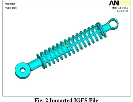
Fig. 1 Geometric Model of Shock Absorber
The geometric model of the shock absorber has been created using Creo. After the creation of the geometric model in a
complete form, it is exported as an IGES file and is imported to ANSYS (A pre and post processor)
Fig. 2 Imported IGES File
Element Type : Solid 20 node 95 Stainless Steel
Material Properties : Young’s Modulus (EX) : 200000N/mm2 Poisson’s Ratio (PRXY) : 0.28 Density : 0.000007612kg/mm3
Element Type: Pipe Element Carbon Steel
Material Properties: Young’s Modulus (EX) : 210000N/mm2 Poisson’s Ratio (PRXY) : 0.29
International Journal of Research in Advent Technology, Special Issue, March 2019
E-ISSN: 2321-9637
3rd National Conference on Recent Trends & Innovations In Mechanical Engineering 15th & 16th March 2019
Available online at www.ijrat.org
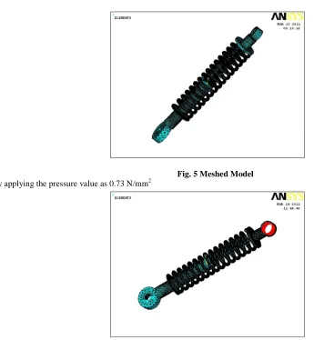
Fig. 3 Meshed Model
Normally the top eye end of shock absorber is connected to body of the vehicle and bottom eye end is connected to frame of the vehicle. Whenever the vehicle moves on uneven surface the load will be acted on top surface of the shock absorber and displacement changes occurred in
bottom portion. So that for applying loads for this analysis part, by applying pressure on top surface and displacement values are applied on inner surface of bottom eye end. By applying pressure value as 0.73 N/mm2
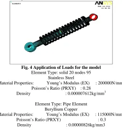
Fig. 4 Application of Loads for the model
Element Type: solid 20 nodes 95 Stainless Steel
Material Properties: Young’s Modulus (EX) : 200000N/mm2 Poisson’s Ratio (PRXY) : 0.28
Density : 0.000007612kg/mm3
Element Type: Pipe Element Beryllium Copper
Material Properties: Young’s Modulus (EX) : 115000N/mm2 Poisson’s Ratio (PRXY) : 0.3
International Journal of Research in Advent Technology, Special Issue, March 2019
E-ISSN: 2321-9637
3rd National Conference on Recent Trends & Innovations In Mechanical Engineering 15th & 16th March 2019
Available online at www.ijrat.org
Fig. 5 Meshed Model
By applying the pressure value as 0.73 N/mm2
Fig. 6 Application of Loads
5. CONCLUSION
After doing analysis for two different materials, the maximum stress for carbon steel is 110.856 MPa and beryllium copper is 220.298 MPa and displacement values for carbon steel is 0.352 e -4 and beryllium copper is 0.427 e
-4
. The maximum yield stress for High Carbon Steel is 714Mpa whereas for Beryllium Copper is 725MPa. Finally the beryllium copper has high yield stress when compared to high carbon steel and the stress value obtained from analysis is less than maximum yield stress value. Now a days spring steels are used for manufacturing of springs, by performing this analysis beryllium copper can be used for manufacturing of springs.
REFERENCES
[1] Mulla, T. M., Kadam, S. J., & Kengar, V. S. (2012). Finite element analysis of helical coil compression
spring for three wheeler automotive front
suspension. Int. J. Mech. Ind. Eng, 2(3), 74-77
[2] Shigley J. E., Mischke C. R., “Mechanical Engineering Design”, Fifth Edition, McGraw Hill Inc., 1989 [3] Wahl A. M., “Mechanical Springs”, Second Edition,