ISSN(Online): 2320-9801
ISSN (Print): 2320-9798
I
nternational
J
ournal of
I
nnovative
R
esearch in
C
omputer
and
C
ommunication
E
ngineering
(An ISO 3297: 2007 Certified Organization)
Vol. 4, Issue 8, August 2016
Suspended Rectangular Microstrip Antenna
with Rectangular Slit
Suryakanth Nirate1, S.L.Mallikarjun2, R.M.Vani3, P.V.Hunagund4
Research Scholar, Dept. of Applied Electronics, Gulbarga University, Kalaburagi, Karnataka, India1
Guest faculty, Dept. of Applied Electronics, Gulbarga University, Kalaburagi, Karnataka, India2
Professor & Head, Univ. Sci. Inst. Centre (USIC), Gulbarga University, Kalaburagi, Karnataka, India3
Professor, Dept. of Applied Electronics, Gulbarga University, Kalaburagi, Karnataka, India4
ABSTRACT: A major disadvantage of the micro strip-patch antenna is its inherently narrow impedance bandwidth of only a couple of per cent. Intensive research is going on to develop bandwidth-enhancement techniques by keeping its size as small as possible. In this paper a suspended rectangular microstrip antenna with rectangular slit (SRMSARS) is presented. Obtained bandwidth is 15.71% & 50.50% respectively with respect to center frequency. The substrate material of FR-4 with relative permittivity 4.4 and loss tangent of 0.0245 is used in this proposed antenna. The return loss and radiation pattern have been measured by using Vector Network Analyser.
KEYWORDS: Rectangular slit, Suspended, Microstripline Feed, Rectangular Patch antenna.
I. INTRODUCTION
Deschamps first proposed the concept of the MSA in 1953 [1]. However, practical antennas were developed by Munson [2, 3] and Howell [4] in the 1970s. The numerous advantages of MSA, such as its low weight, small volume, and ease of fabrication using printed-circuit technology, led to the design of several configurations for various applications [5–9]. With increasing requirements for personal and mobile communications, the demand for smaller and low-profile antennas has brought the MSA to the forefront. An MSA in its simplest form consists of a radiating patch on one side of a dielectric substrate and a ground plane on the other side. Microstrip patch antennas, particularly with rectangular patch, is widely used in mobile radio, and a varietyof other wireless communications devices for which small size, light weight, and low profile are the main considerations. As is well known, a major attribute that has limited their application capability is their inherent narrow impedance bandwidth (typically 2% to 3%). In certain applications, such as high data-rate wireless transmission, this low bandwidth is not adequate. In order to meet the demand for larger bandwidth, several techniques have been reported [10].The simplest and most widely used structure in this category is the suspended microstrip which, in view of the air gap next to the ground plane, offers improved efficiency.
When an antenna must operate at two frequencies that are far apart, a dual-frequency antenna can be used to avoid the use of two separate antennas. When two or more resonance frequencies of a MSA are close to each other, a broad BW is obtained. When these are separated, dual-band operation is obtained [11]. In this paper a Suspended Rectangular Microstrip Antenna with rectangular slit (SRMSARS) is presented.
II. PROPOSED ANTENNA DESIGN
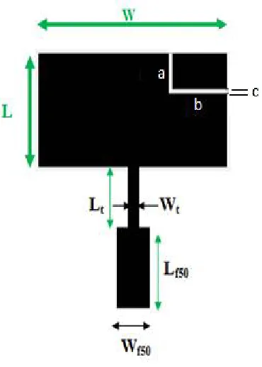
In the proposed design, the antenna has been designed for 6 GHz and is fed using microstrip line feed. The length and width of the rectangular patch are Land Wrespectively. The feed arrangement consists of quarter wave transformer of length Ltand width Wtwhich is connected as a matching network between the patch and the microstripline feed of
length Lf50 and width Wf50. At the very first the antenna is designed in a suspended mode. In the suspended
ISSN(Online): 2320-9801
ISSN (Print): 2320-9798
I
nternational
J
ournal of
I
nnovative
R
esearch in
C
omputer
and
C
ommunication
E
ngineering
(An ISO 3297: 2007 Certified Organization)
Vol. 4, Issue 8, August 2016
Fig.2. shows the top view geometry of SRMSARS. On the top of right side of the patch, rectangular slit is inserted. The dimensions of the slits are a = λ/20.66 mm, b = λ/9.59 mm respectively and c = 0.5 mm respectively.
ISSN(Online): 2320-9801
ISSN (Print): 2320-9798
I
nternational
J
ournal of
I
nnovative
R
esearch in
C
omputer
and
C
ommunication
E
ngineering
(An ISO 3297: 2007 Certified Organization)
Vol. 4, Issue 8, August 2016
Table.1 shows the design parameters of the proposed antenna.
Table 1: Design Parameters of the Antenna
Parameter
Value in mm
Length of the Patch(L)
10.38
Width of the Patch(W)
15.21
L
t6.35
W
t0.46
L
f506.29
W
f503.06
Air gap (
)0
III.RESULTS AND DISCUSSION
The antenna bandwidth over return loss less than -10 dB is measured experimentally on Vector Network Analyser (Rohde & Schwarz, Germany make ZVK model 1127.8651.60). The variation of return loss verses frequency of SRMSARS is as shown in Fig. 3.
4.0G 6.0 G 8.0G 10 .0G 12.0G 1 4.0 G 16 .0G
-35 -30 -25 -20 -15 -10 -5 0
f2 f1
B W 1
B W 2
R
e
tu
rn
l
o
s
s
(
d
B
)
Frequ ency (H Z)
S R M S A R S
Fig. 3 Variation of Return loss Verses Frequency of SRMSARS
It is observed from the graph that the antenna operates for two bands of frequencies i.e, Band 1 (BW1) and Band 2
ISSN(Online): 2320-9801
ISSN (Print): 2320-9798
I
nternational
J
ournal of
I
nnovative
R
esearch in
C
omputer
and
C
ommunication
E
ngineering
(An ISO 3297: 2007 Certified Organization)
Vol. 4, Issue 8, August 2016
Table 2: Experimental results of SRMSARS
Table.2 shows the experimental results of SRMSARS.T he proposed antenna resonates at 10.05 GHz. From the table it is observed that bandwidth of the BW2 is more compare to BW1.
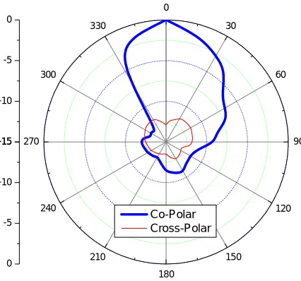
Fig.4 Radiation Pattern of Proposed SRMSARS
Fig.4 shows the radiation pattern of SRMSARS. It is seen that antenna shows co-polarization and better minimum cross-polarization. Further the antenna shows maximum radiation in broad side direction.
IV.CONCLUSION
In this paper a Suspended Rectangular Microstrip Antenna with Rectangular Slit (SRMSARS) is presented. From the detailed experimental study it is concluded that, antenna operates for two bands of frequencies in the range of 3 GHz to 16 GHz. With these features the proposed antennas may find application in microwave communication systems operating in the frequency range of 3 to 16 GHz. Antenna gives better bandwidth of 15.71 % and 50.50 % respectively.
REFERENCES
Antenna
name
Resonant
Frequency
(GHz)
Return Loss (dB) Bandwidth (%)
Band1
Band2
BW
1BW
2SRMSARS
10.05
-20.85
-30.09
15.71
50.50
-15 -10 -5 0
0
30
60
90
120
150
180 210
240 270
300
330
-15
-10
-5
0
ISSN(Online): 2320-9801
ISSN (Print): 2320-9798
I
nternational
J
ournal of
I
nnovative
R
esearch in
C
omputer
and
C
ommunication
E
ngineering
(An ISO 3297: 2007 Certified Organization)
Vol. 4, Issue 8, August 2016
5. Bahl, I. J., and P. Bhartia, Microstrip Antennas, Dedham, MA: Artech House, 1980.
6. Carver, K. R., and J. W. Mink, ‘‘Microstrip Antenna Technology,’’ IEEE Trans.Antennas Propagation, Vol. AP-29, January 1981, pp. 2–24.
7. Mailloux, R. J., et al., ‘‘Microstrip Array Technology,’’ IEEE Trans. Antennas Propagation,Vol. AP-29, January 1981, pp. 25–37.
8. James, J. R., et al., ‘‘Some Recent Development in Microstrip Antenna Design,’’IEEE Trans. Antennas Propagation, Vol. AP-29, January 1981, pp. 124–128.
9. James, J. R., and P. S. Hall, Handbook of Microstrip Antennas, Vol. 1, London: Peter,Peregrinus Ltd., 1989.
10. Shushant Jain, et al Bandwidth Enhanced E- Shaped Microstrip Antenna With Pair Of Wide Slits”, International Journal of Computer and Electronics Research, Volume 1, Issue 4, December 2012,pp.187-191.
11. Girish Kumar and K.P.Ray, “Broadband Microstrip Antennas”, Artech House London.ISBN 1-58053-244-6.
BIOGRAPHY
Mr. Suryakanth Nirate received his M.Sc. Applied Electronics degree from Gulbarga University, Kalaburagi in the year 2002 and completed M.Phil. Degree in the year 2007 from same Department. He is pursuing his Ph.D degree in Dept. of Applied Electronics, Gulbarga University, Kalaburagi in the field of Microwave Electronics. His areas of interest include Suspended Microstrip Antennas and Microstrip antennas. He has 4 publications in reputed International/National Journals.
Dr. S. L. Mallikarjun received his M.Sc., M.Phil. and Ph.D. degree in Applied Electronics from Gulbarga University, Kalaburagi in the year 2005, 2007 and 2011 respectively. He is working in Dept. of Applied Electronics, Gulbarga University, Kalaburagi. He has more than 80 publications in reputed International/National Journals and in conference and symposia. His Research interest includes microstrip antenna, arrays and dielectric resonator antenna.
Dr.Vani. R.M. received her B.E. in Electrical and Electronics from the B.I.E.T., Davanagere, Karnataka, and M.Tech in Industrial Electronics from S.J.C.E., Mysore. She has received her Ph.D in Applied Electronics from Gulbarga University, Kalaburagi, in year 2005. She is working as Professor and Head, University Science Instrumentation Center, Kalaburagi, since 1995. She has more than 85 research publications in National and International reputed journals and Conference proceedings. She presented many research papers in India & Abroad. She has conducted several courses, workshops for the benefit of faculties and field engineers. Her areas of interest are microwave antennas, PC based Instrumentation, Embedded controllers and wireless communication. She has one UGC major research project to her credit.