Optimize Data Collection in Wireless Sensor
Networks Using
Multi-Hop Connected
Clustering
Dr.K.Selvaraj, S.Sathiyaraj
Head of the Department, Arignar Anna Government Arts College, Attur, India. Department of Computer Science, Arignar Anna Government Arts College, Attur,India.
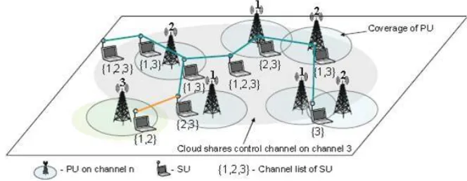
ABSTRACT: Cognitive networks enable efficient sharing of the radio spectrum. Control signals used to setup a communication and broadcast to the neighbors in their particular channels of operation. This paper deals with broadcasting challenge specially in multi-hop CR ad hoc networks under practical scenario with collision avoidance have been address. Exchanging control information is a critical problem in cognitive radio networks. Selective broadcasting in multi-hop cognitive radio network in which control information is broadcast over pre-selected set of channels. We introduce the idea of neighbor graphs and minimal neighbor graphs to obtain the necessary set of channels for broadcast. Selective broadcasting reduces the delay in disseminate control information and yet assures successful transmission of information to all its neighbors. It is also confirmed that selective broadcasting reduces redundancy in control information and hence reduces network traffic.
KEYWORDS: Broadcasting, Neighbor Graphs And Minimal Neighbor Graphs. I. INTRODUCTION
possibility that a channel is common with all the cognitive user is little [4]. As a result, several of the nodes may not be available using a single channel. So, it is necessary to transmit the control information on more than one channel to make sure that every neighbour receives a copy [5]. With the raise in number of nodes in the system, it is potential that the nodes are scattered over a huge set of channels. As a effect, cost and delay of communications over all these channels increases. A simple, yet efficient solution would be to identify a small separation of channels which cover all the neighbors of a node. Then use this set of channels for exchange the control information. This concept of transmitting the control signals over a selected group of channels as an alternative of flooding over all channels is called selective broadcasting and forms the basic design of the paper. Neighbor graphs and minimal neighbour graphs are introduced to find the minimal set of channels to transmit the control signals.
II. EXISTING SYSTEM
Broadcast is an important process in ad hoc networks, especially in distributed multi-hop multi-channel networks. In CR ad hoc networks, different SUs may obtain different sets of accessible channels. This non-uniform channel availability impose special plan challenges for broadcasting in CR ad hoc networks. So we introduce fully-distributed broadcast protocol in a multi-hop CR ad hoc network. In this protocol, control information exchange among nodes, such as channel accessibility and routing information, is critical for the realization of most networking protocols in an ad hoc network. In cognitive network, each node has a set of channels available; a node receives a message only if the message was send in the channel on which the node was listen to. So, to make sure that a message is successfully sent to all neighbors of a node, it has to be broadcast in every channel. In a cognitive environment, the number of channels is potentially large. As a result broadcasting in each channel causes a large delay in transmitting the control information. problem defined in this project1)Broadcasting delay is high.2)Redundancy Occur.3)Sent control information to all nodes.4)High congestion.5)Network traffic is high.
III. PROPOSED SYSTEM
Broadcasting control information overall channel will origin a large delay in setting up the communication. Thus, exchange control information is a main problem in cognitive radio networks. In our proposed work, we deals with selective broadcasting in multi-hop cognitive radio network in which, control information is transmit over pre-selected set of channels. We establish the concept of neighbor graphs and minimal neighbor graphs to derive the essential set of channels for transmission. Neighbor graphs and minimal neighbor graphs are introduced to find the minimal set of channels to transmit the control signals. A neighbor graph of a node represents its neighbors and the channels over which they can communicate. A minimal neighbor graph of a node represent its neighbors and the minimum set of channels through which it can reach all its neighbors. Advantages of proposed system.1)Control information is transmitted over pre-selected set of channels.2)Network traffic is reduced3)Low Broadcasting delay4)Less congestion, contention5)No common control channel6)Redundancy reduced.
IV. SELECTIVE BROADCASTING
In a MHCRN, each node has a set of channels presented when it enters a network. In order to become a part of the network and start communicate with other nodes, it has to initial know its neighbors and their channel information. Also, it has to let other nodes know its occurrence and its accessible channel information. So it broadcasts such information over all channels to make sure that all neighbors obtain the message. Similarly, when a node wants to start a communication it should replace certain control information useful, for example, in route discovery. However, a cognitive network location is dynamic due to the primary user’s traffic. The number of available channels at each node keeps changing with time and location. To keep all nodes efficient, the information change has to be transmitted over all channels as quickly as possible. So, for successful and efficient coordination, fast dissemination of control traffic between neighboring users is required. So, minimal delay is a important factor in promptly disseminating control information. Hence, the goal is to decrease the broadcast delay of each node.
Now, consider that a node has M available channels. Let Tb be the minimum time required to broadcast a control message. Then, total broadcast delay = M ×Tb. So, in order to have lower broadcast delay we need to reduce M. The value of Tb is dictated by the particular hardware used and hence is fixed. M can be reduced by discovering the minimum number of channels, M ' to broadcast, but still making sure that all nodes obtain the message. Thus, communications over carefully selected M' channels instead of blindly broadcasting over M (presented) channels is called Selective Broadcasting. Finding the minimum number of channels M ' is accomplished by using neighbor graphs and discovering the minimal neighbor graphs. Before explaining the idea of neighbor graph and minimal neighbor graph it is essential to understand the state of the network when selective broadcasting occurs and the difference among multicasting and selective broadcasting.
A. State Of The Network
When a node enter in the network for the first time, it has no information about its neighbors. So, initially, it has to broadcast over all the feasible channels to reach its neighbors. This is called the initial state of the network. From then on, it can begin broadcasting selectively. Network steady state is reached when all nodes know their neighbors and their channel information of each node. Since selective broadcasting starts in the steady state, all nodes are assumed to be in steady state during the rest of the conversation.
B. Multicasting And Selective Broadcasting
Broadcasting is the environment of wireless communication. As a result, Multicasting and Selective broadcasting might appear related, but they change in basic idea itself. Multicasting is used to send a message to a specific group of nodes in a particular channel. In a multichannel environment where the nodes are listening to different channels, Selective broadcasting is an essential way to transmit a message to all its neighbors. It uses a selected set of channels to transmit the information instead of broadcasting in all the channels
.
V. NEIGHBOR GRAPH AND MINIMAL NEIGHBOR GRAPH FORMATION
In this section, the design of neighbor graph and minimal neighbor graph is introduced and the construction of the same is explain. A neighbor graph of a node represent its neighbors and the channels over which they can communicate. A minimal neighbor graph of a node represents its neighbours and the minimum set of channels through which it can reach all its neighbors. The complete construction of both such graphs is explained below.
A. Construction Of Neighbor Graph
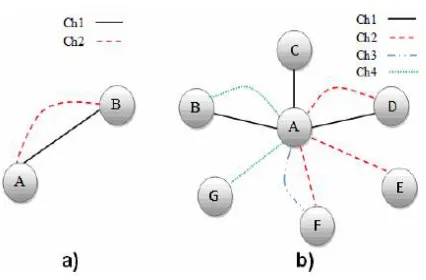
Figure 2. a) Nodes A and B linked by 2 edges. b) Representation of node A with 6 neighbors
consider a graph with 7 nodes from A to G and 4 different channels as shown in Fig. 2b. Node A is considered the source node. It has 6 neighboring node, B through G. The edges signify the channels through which A can communicate with its neighbors. For example, A and D node can communicate through the channels 1 and 2. It means that they are neighbors to each other in channels 1 and 2. So this graph is called the neighbor graph of node A. Similarly every node maintains its neighbor graph.
B. Construction Of Minimal Neighbor Graph
To decrease the number of broadcasts, the minimum number of channels through which a node can reach all its neighbours has to be chosen. A minimal neighbor graph contain set of channels. Let DC be a set whose elements represent the degree of each channel in the neighbor graph. So, DCi represents the number of edges corresponding to channel Ci . For example, the set DC of the graph in Fig. 2b is: DC ={3,3,1,2}. To build the minimal neighbor graph, the channel with the highest degree in DC node is chosen. All edges corresponding to this channel, as well as all nodes other than the source node that are associated to these edges in the neighbor graph, are removed. This channel is added to a set called ‘Essential Channel Set’, ECS which as the name imply, is the set of required channels to reach all the neighboring nodes. ECS originally is a null set. As the edges are removed, the corresponding channel is added to ECS.
Figure 3. Final minimal neighbor graph of fig. 2b.
VI. PERFORMANCE EVALUATION
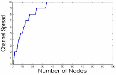
In this section the performance of the selective broadcast is compared with complete broadcasting by studying the delay in broadcasting control information and redundancy of the received packets. The performance evaluation used in all these experiments is shown below. For each experiment, a network area of 1000m×1000m is considered. The number of nodes is different from 1 to 100. All nodes are deployed randomly in the network. Each node is assign a random set of channels changing from 0 to 10 channels. The transmission range is set to 250m. Each data point in the graphs is an average of 100 runs. Before looking at the routine of the proposed idea, two observations are made that help in understanding the simulation results. Fig. 3 shows the plot of channel spread as a function of number of nodes. Channel spread is defined as the combination of all the channels covered by the neighbors of a node.
Figure 4 Plot of channel spread with respect to number of nodes for a set of 10 channels.
A. Broadcast Delay
In this part transmission delay of selective broadcast and complete broadcast are compared. Broadcast delay is defined as the total time taken by the node to effectively broadcast one control message to all its neighbors. Each point in the graph is the average wait of all nodes in the network. The minimum time to broadcast in a channel is assumed to be 5 msec.
obtainable channels. Since these channels are assign randomly to each nodes, the average number of channels at each node is almost constant.
The average delay increases linearly with large number of channels in the case of successful broadcast, because the node transmit in all its available channels. On the other hand, in selective broadcasting, the rate of increase in delay is small. This is because, increasing the amount of channels, the number of neighboring nodes enclosed by each channel also increases. As a result, the minimum channel set required to cover all the neighbors remains constant and keeping the delay constant.
B. Redundancy
‘Redundancy’ is defined as the total number of additional copies of a message received by all nodes in the network if all of them transmit control messages once. It is observed that the number of redundant messages increases with amount of nodes in both the cases and the curve are similar in shape. This implies that the difference in redundancies is not a purpose of the number of nodes. The average M to M ' ratio was found to be 2.5. This concludes that the reduced total redundancy is due to the reduction in channel set in selective broadcast. It has been verified that redundancy is reduced by a factor of (M /M ').
The rate of increase of redundancy is lower in selective broadcast when compared to successful broadcast. In complete broadcast, the number of redundant messages at each node is equal to the number of channels it has frequent with the sender. Therefore, with increase in number of channels the redundant messages approximately increase linearly whereas in selective broadcast the increase is small due to the selection of minimum channel set. In this section, it has been demonstrated that selective broadcasting provides lower transmission delay and redundancy. It should be noted that, due to the decrease in redundancy of messages, there will be less congestion in the network and hence, there is possible for improvement in throughput by using selective broadcasting.
VII. CONCLUSION
In this paper the concept of selective broadcasting in MHCRNs is introduced. A minimum set of channels called the Essential Channel Set (ECS), is derived by neighbor graph and minimal neighbor graph. This set contains the minimum number of channels which cover up all neighbors of a node and hence transmitting in this selected set of channels is called selective broadcasting is compared to complete broadcast or flooding. It performs better with increase in number of nodes and channels. It has also been exposed that redundancy in the network is reduced by a factor of (M /M '). As a result there is a possible for improvement in overall network throughput.
REFERENCES
[1] Joseh Mitola and G. Q. Maguire. “Cognitive radio: making software radios more personal” IEEE personal Communications, 6(4):13–
18,1999.
[2] Chunsheng Xin, Bo Xie, Chien-Chung Shen, “A novel layered graph model for topology formation and routing in dynamic spectrum access
networks”, Proc. IEEE DySPAN 2005, November 2005, pp. 308-317
[3] K. Bian and J.-M. Park, "MAC-layer misbehaviors in multi-hop cognitive radio networks," 2006 US - Korea Conference on Science,
Technology and Entrepreneurship (UKC2006), Aug. 2006.
[4] J. Zhao, H. Zheng, G.-H. Yang, “Distributed coordination in dynamic spectrum allocation networks”, in: Proc. IEEE DySPAN 2005, pp .
259-268, November 2005
[5] G. Resta, P. Santi, and J. Simon, “Analysis of multi-hop emergency message propagation in vehicular ad hoc networks,” in Proc. 8th ACM Int.
Symp. Mobile Ad Hoc Netw. Comput., 2007, pp. 140–149.
[6] Chlamtac and S. Kutten, “On broadcasting in radio networks—Problem analysis and protocol design,” IEEE Trans. Commun.,vol. no . 12, pp.
1240–1246, Dec. 1985.
[7] S.-Y. Ni, Y.-C. Tseng, Y.-S. Chen, and J.-P. Sheu, “The broadcast storm problem in a mobile ad hoc network,” in Proc. 5th Annu. ACM/IEEE
Int. Conf. Mobile Comput. Netw., 1999, pp. 151–162.
[8] J. Wu and F. Dai, “Broadcasting in ad hoc networks based on selfpruning,”in Proc. IEEE Conf. Comput. Commun., 2003, pp. 2240–2250.
[9] J. Qadir, A. Misra, and C. T. Chou, “Minimum latency broadcasting in multi-radio multi-channel multi-rate wireless meshes,” in Proc. IEEE CS
3rd Annu. Sens. Ad Hoc Commun. Netw., 2006, vol. 1, pp. 80–89.
[10] Qayyum, L. Viennot, and A. Laouiti, “Multipoint relaying for flooding broadcast messages in mobile wireless networks,” in Proc. 35th Annu.
[11] Y. Song and J. Xie, “QB2IC: A QoS-based broadcast protocol under blind information for multi-hop cognitive radio ad hocnetworks,” IEEE Trans. Veh. Technol., vol. 63, no. 3, pp. 1453–1466 Mar. 2014.
[12] L. Lazos, S. Liu, and M. Krunz, “Spectrum opportunity-based control channel assignment in cognitive radio networks,” in Proc. IEEE 6th Annu. Commun. Soc. Conf. Sens., Mesh Ad Hoc Commun. Netw., 2009, pp. 1–9.
[13] J. Zhao, H. Zheng, and G. Yang, “Spectrum sharing through distributed coordination in dynamic spectrum access networks,” Wireless Commun. Mobile Comput., vol. 7, pp. 1061–1075, Nov. 2007.
[14] K. Bian, J.-M. Park, and R. Chen, “Control channel establishment in cognitive radio networks using channel hopping,” IEEE J. Sel. Areas Commun., vol. 29, no. 4, pp. 689–703, Apr. 2011.