Article
IMU-Aided Dual-Frequency RFID Based Localization
in LOS/NLOS Hybrid Environment
Jie WU 1,2, MingHua ZHU 1,*, Bo XIAO 1 and Wei HE 2
1 MOE Research Center for Software/Hardware Co-Design Engineering and Application, East China Normal University, Shanghai, China; [email protected],[email protected], [email protected] 2 The Third Research Institute of Ministry of Public Security, Shanghai, China; [email protected] * Correspondence: [email protected]; Tel.: +86-139-1532-0132
Abstract: The mitigation of NLOS (non-line-of-sight) propagation conditions is one of main challenges in wireless signals based indoor localization. When RFID localization technology is applied in applications, RSS fluctuates frequently due to the shade and multipath effect of RF signal, which could result in localization inaccuracy. In particularly, when tags carriers are walking in LOS (line-of-sight) and NLOS hybrid environment, great attenuation of RSS will happen, which would result in great location deviation. The paper proposes an IMU-assisted (Inertial Measurement Unit) RFID based indoor localization in LOS/NLOS hybrid environment. The proposed method includes three improvements over previous RSS based positioning methods: IMU aided RSS filtering, IMU aided LOS/NLOS distinguishing and IMU aided LOS/NLOS environment switching. Also, CRLB (Cramér-Rao Low Bound) is calculated to prove theoretically that indoor positioning accuracy for proposed method in LOS/NLOS mixed environment is higher than position precision of only use RSS information. Simulation and experiments are conducted to show that proposed method can reduce the mean positioning error to around 3 meters without site survey.
Keywords: dual-frequency RFID; indoor localization; non line of sight; received signal strength; inertial measurement unit
1. Introduction
The RFID (Radio Frequency Identification) technology has attracted considerable attentions over the past decades due to its advantages of non-touch, low-cost, high accuracy and long-distance communication. As a key technology of the internet of things, RFID has attracted wide research and has been used in many fields. One of most important RFID based applications is indoor localization.
Current RFID based positioning algorithm can be divided into two categories [1]. The first kind of algorithms is based on the transmission model to get the distance between the reader and tags using received signal strength [2-4]. With the derived distance, the tri-lateration method is used to calculate the location of the tag. The second solution is the fingerprint based indoor localization method [5-8]. Before the location measurement, the location of tags and the corresponding RSS are recorded as the fingerprint of the environment. In the process, when the system receives the RF signal strength, the information is matched to get the position of the unknown tags. The fingerprint matching method needs a higher dependence on the stability of the surrounding environment. If surrounding environment changes, the fingerprint should be re-established. In this paper, we mainly focus on the first solution to use the transmission model to get the distance between tag and reader.
In real applications, there are always obstacles between the readers and unknown tags, which would result into measurement deviation. This situation is defined as NLOS (Non-light-of-sight) and we call the situation as LOS (light-of-sight) when there are no obstacles between the readers and unknown tags. In the real scenario, the environment is so complex which includes both LOS and NLOS signal propagation that it is difficult to establish an accurate model to work on this problem
[9-12]. A lot of paper proposed different kinds of method. Sarfraz [13] proposed a robust multi-lateration algorithm for localizing sensor nodes in cluttered environments to decrease the large distance measurement errors introduced by NLOS signal propagation. Yang [14] proposed a two-step statistics-based least squares (SLS) method which consists of a NLOS bias elimination and linear least squares (LLS) process. Wylie and Holtzman [15] proposed a method to identify the NLOS error with the measurement noise standard deviation value. Guven [16] proposed a weighted least square algorithm based on the channel characteristics for localization in cluttered environments, and tried to mitigate the NLOS influence through a smaller weight for NLOS data.
This paper put forward an IMU aided indoor positioning method in NLOS and LOS mixed environment based on dual-frequency RFID technology. The sliding windows are used to filter RSS with the assisting of IMU. The ratio of processed RSS and relative displacement of tag movement was adopted to find the singular point of η in the process. Then through the singular point, the switch point of NLOS and LOS environment is detected. There, we use different readers for trilateral positioning algorithm to find the location of the unknown tags. When the tags carriers walk between NLOS/LOS environments, the environment switch would result in positioning error. The IMU is used to assist tag positioning. The paper calculated CRLB of proposed method, and concluded that the use of IMU into the RSS localization method was superior to the effect of only use RSS for positioning.
The rest of the paper is organized as follows.The next section describes the state-of-art of NLOS mitigation methods. The proposed algorithm is detailed in section 3. In section 4, the CRLB of the algorithm is calculated. The simulation about the proposed method is performed in section 5 and the experiment was conducted in section 6. Conclusion and discussion are made in the last section.
2. Related Work
When the wireless signals are used for indoor localization, they are impossible to avoid the influence of NLOS environment. Most of wireless signals based indoor positioning methods are sensitive to the NLOS environment, such as BLUETOOTH, WIFI, UWB, RFID and so on. Many indoor positioning approaches [17-21] have been proposed to distinguish and mitigate the positioning error introduced by LOS/NLOS mixed environment.
Jordi and Pau [22] provide a robust Bayesian inference framework to deal with target localization under NLOS conditions. The paper takes advantage of the conditionally Gaussian formulation of the skew t-distribution, and then uses computationally light Gaussian filtering and smoothing methods as the core of the proposed approach. Gao and Zhang [23] formulate a robust least square (RLS) problem to jointly estimate the source location and the transmission time by using an asynchronous sensor network under non-line-of-sight conditions. Rather than processing all measurements via a single filter, the proposed algorithm distributes the measurements among several local filters. The paper uses distributed filtering and data association techniques to identify the abnormal measurements due to NLOS. Li [25] improved the NLOS mitigation algorithm to reduce the computation complexity and speed the convergence by using only three distance measurements instead of all available distance measurements.
In the RSS based indoor localization, several works have proposed to identify and mitigate the NLOS environment in LOS/NLOS situation. To make a distinguish between NLOS and LOS environment, the paper [24] derives a comparison method on the basis of belief intervals and characterize the signal features on the LOS and NLOS conditions for different field experiments. Chen and Feng [26] proposed SIDE (statistical inference distance estimation) algorithm to provide a consistent distance estimator when the particle number is larger than an inferential theoretic lower bound given a confidence level and an error constraint. However, these techniques are not suitable for LOS/NLOS mixed environments and the two situation switches frequently.
3. Preliminaries
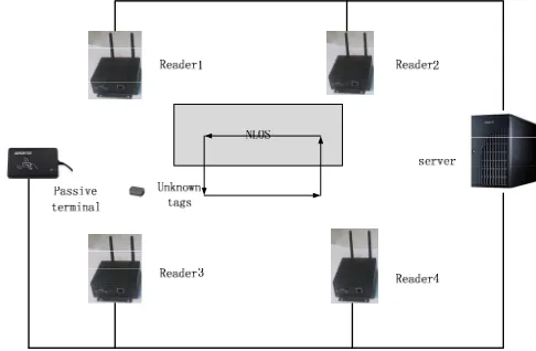
tag is read by reader, its initial location can be confirmed. Because IMU is not sensitive to the environment, it is used to get relative position between the current position of the unknown tags and the previous position. The RSS data are used in the model of the signal strength and distance between the readers and the location of the unknown tags. Then the LOS and NLOS environments are distinguished with the aid of IMU. We use different model parameters according to the NLOS and LOS to get a more accurate location. In this way, under the condition of LOS and NLOS, the algorithm can still keep relatively stable and higher positioning accuracy. For clearly describing the proposed solution and conducting the simulation, we designed a simple scenario as shown in figure 1.
Figure 1. The deployment the simulate system. The four readers are deployed in the simulate system. The initial tag position is determined by passive terminal. The tags carriers walk in LOS/NLOS hybrid environment. The gray rectangle represents NLOS environment, and the white area represents LOS environment.
The paper used the classic path propagation model (1) to describe the relationship about RSS and distance between the readers and unknown tags. In this equation, ξ(t) contains environment noise and equipment noise. As we mentioned in the assumption, we ignore the equipment noise. Regarding that all readers in this paper receive the same RSS for one tag in the same distance, ξ(t) only denotes the environment noise.
0
10 log
10/
0( )
ri i
P
= −
P
η
d d
+
ξ
t
(1)where Pri refers to the received power by the ith reader in the di distance, η denotes the path loss
coefficient. ξ(t) denotes the environment noise and obeys the Gauss distribution N(0,σ), P0 denotes
the received power by the ith reader in the d0 distance.
4. Materials and Methods
In this section, we make a detail description about the proposed algorithm. The section is divided into four parts. The first part is to calculate the initial position and initial parameters of the model. The second part designs an IMU aided RSS filter and the third part distinguishes and eliminates the NLOS and LOS. In the fourth part, IMU Aided LOS/NLOS Environment Switch is conducted.
4.1 Initial Position Confirmation and Model Parameters Calculation
information (such as IMU). The surrounding readers read RSS values and information of tag. In order to simplify the calculation, passive terminal is deployed in LOS environment and in this place, the initial obey normal distribution N (0, σ), and the path loss is known in advance. Through this information and the model of equation (1), we can preliminarily confirm the model of transmission loss and the parameters of the Gaussian noise.
2 2
(
)
(
)
i i i
d
=
x
−
x
+
y
−
y
(2)0 0
1 1
0 0
0
2 2
0
0 0
10 log
P 1 1
1 1 10 log
... ...
... ...
1 1 10 log
los r
r los
rN los N
d P
P d
n
P d
η η
η
= +
(3)
Where the [P0r1,…,P0rN]T is the received power by readers when the tag is activated by passive
terminal. N denotes the readers received number of N data. di refers to the distance between
unknown tag and reader, We rewrite it as matrix form.
C
P DX
=
+
(4)Where P denotes [P0r1,…,P0rN]T, D denotes 2 x N matrix. The parameter C denotes
[10ηloslog(d01),…, 10ηloslog(d0N)], and X denotes [P0,N0]T. We solve the matrix and get the initial
parameter as follow:
1
(
T)
T( -C)
X
=
D D
−D P
(5)4.2 IMU Aided RSS Filtering
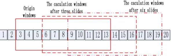
In a relatively short period of time, the fluctuation of IMU value is far less than fluctuation of RSS. In this way, the IMU would measure more accurately the relative position about the tags movement than the RSS. So in this paper, the IMU and RSS are fused with kalman filter to get more stable data for received signal strength. The IEZ+ method [27,28] is a appropriate choice to get the relative displacement, in which accumulated errors of the proposed method is approximately 1% of the total traveled distance. So we adopt IEZ+ method to get the relative displacement with IMU in this paper.
Figure 2. The sliding windows for the RSS filtering with IMU.
to the recent n value. So the relation between the estimated received power and RSS by readers can be expressed as equation 6.
( ) ( ) ( ) ( )
1
ˆ ( ) j ( | )
mj m j m j m i m i
i
P E P p X P X P P
=
= =
= = (6)where Pˆm j stands for the jth estimated received power, and Pm(j) stand for the RSS by mth reader in jth
times. The p(X=Pm(j)|X=Pm(i)) stands for the transition probability from previous RSS to jth RSS state.
The transition probability can be obtained by the relative position with IMU.
( ) ( )
0 ( m j | m i ) ( )= ( )/ n ( )
t
p X P X P
ζ
i S i S t == = =
(7)where S(i) refers to the relative displacement calculated by IMU, ζ(i) refers to the normalized relative displacement. So the RSS filter equation with IMU is denoted by:
( ) ( )
1
0
( )
ˆ
(
)
( )
jmj m j j m i
i t
S i
P
E P
P
S t
=
=
=
=
(8)where j = 1, 2, 3 … n.
Figure 3. The figure shows the IMU assisted RSS data filtering. The blue line is simulated received signal strength. The green line is received signal strength with the Gauss noise. The red is filtered data for RSS. It is shown that the IMU is effective for the RSS filtering.
4.3 IMU Aided NLOS Error Mitigation
The proposed method uses the ratio of processed RSS and relative displacement of tag movement to distinguish the different path loss environment. With the equation 1, for established P0
and d0, Pr is a function of η and d. That is Pr=F(η, d). The partial derivative of Pr to d is given by: 1 1
10
ln(10)
r
P
d
η
d∂ = − ⋅ ⋅ ⋅
∂ (9)
According to the equation 1,the distance between the position of unknown tags and the position of reader can be denoted by:
0
10 0
10
r r P P
d d
η−
=
(10)0 10 0 1 1 10 10 ln(10) r r P P r P d d η η − − ∂ = − ⋅ ⋅ ⋅ ⋅ ∂ (11)
With the help of MATLAB tool, the path loss parameter η is derived by equation 12.
0 0 0
(P )
10 (0, )
100 (P ) ln(10)
r r r
r r P P lambertw d d P η − ∂ ⋅ − ⋅ ⋅ ∂ = − − ⋅ (12)
where the function lambertw() is Lambert W Function. This function is the inverse function of f(w), where f(w)=w.exp(w). exp(w) is a function index, and w is plural. We define Δd as di-di-1, and Δτ is
relative position between the position and previous position, which we can derivate with IMU. In this paper, we assume d >> Δd and d >> Δτ. Then the ratio of processed RSS and relative displacement of tag movement is expressed as:
r r
P P
d α τ
∂ ≈ ⋅∂
∂ ∂ (13)
where α is constant parameter. Combining the equation 12 and equation 13, the result of η is denoted by:
0
0
0
(P )
10 (0, )
100 (P ) ln(10)
r r r
r r P P lambertw d P α τ η − ∂ ⋅ − ⋅ ⋅ ⋅ ∂ ≈ −
− ⋅ (1
4)
In equation 14, when tag carrier walks in LOS/NLOS mixed environment as figure 1, the RSS changes sharply, while the relative position changes smoothly. It would cause η changes sharply. Under this condition, η would produce singular value. According to the location of the singular value, we calculate the η separately in the whole process. Then the procession is separated into two parts. We pick some of the data at the junction of LOS/NLOS environment. The data separately satisfies the following equations.
1 0
10 log ( / )
1 10 1 0 1( )
rP
= −
P
η
d d
+
ξ
t
(15)2 0
10 log
2 10 2/
0 2( )
rP
= −
P
η
d d
+
ξ
t
(16)In equation 15 and 16, because points are picked so close, we assume that the distance d1 and d2
between reader and tag are equal. Two equations are combined and get the ratio between η1 and η2.
2 0 1 2 1 1 0 1 M r t t M r t t P P P P η η = = − = −
(17)Through the above equation, we can distinguish which part is LOS, and which part is NLOS.
4.4 IMU Aided LOS/NLOS Environment Switch
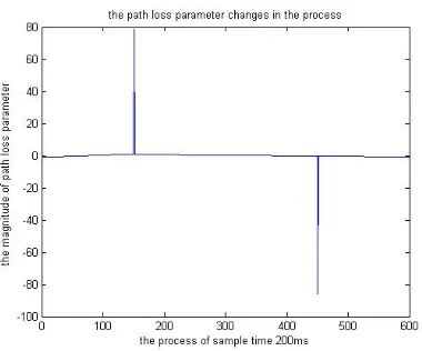
Figure 4. The figure shows the change of path loss parameter in the procession. As it is shown, the point at the magnitude of 80 is the singular value of path loss parameter.
Figure 5. The Figure shows the position error with the aid of IMU. In the surrounding of singular point, we use the IMU aided navigate to keep the position stable.
4.5 Localization of Unknown Tags
Trilateral method is used to get the real location of unknown tags. The distance between reader and tag is calculated by the RSS according to the algorithm. According to the LOS and NLOS propagation path detection, path can be divided into different process section to calculate the distance.
2 2 2
1 1 1
2 2 2
2 2 2
2 2 2
ˆ
( ) ( )
ˆ
( ) ( )
...
ˆ ( m ) ( m ) m
x x y y d
x x y y d
x x y y d
− + − =
− + − =
− + − =
(18)
where (x, y) is the position of unknown tag, the (x1,y1),(x2,y2),…,(xm, ym) are the position of readers.
d1, d2,…, dm are the distances we have estimated by section 2. The last equation is used to minus the
2 2 2 2 2 2
1 1 1 1 1
2 2 2 2 2 2
2 2 2 2 2
2 2 2 2 2 2
1 1 1 1 1
2 ( ) 2 ( )
ˆ ˆ 2 ( ) 2 ( )
...
ˆ ˆ 2 ( ) 2 ( )
m m m m m
m m m m m
m m m m m m m m m m
x y d d x y x x x y y y
x y d d x y x x x y y y
x− y− d d− x y x x− x y y− y
+ + − − − = − + − + + − − − = − + − + + − − − = − + − (19)
The matrix of the equation is given by:
P XC
=
(20)where X = [x, y]T, P is the expression on the left equation . The matrix of C is expressed as:
1 1
2 2
1 1
2( ) 2( )
2( ) 2( )
... ...
2( ) 2( )
m m
m m
m m m m
x x y y
x x y y
C
x− x y− y
− − − − = − −
The location of unknown tag is given by:
1
(
)
T T
X
=
PC CC
− (21)5. CRLB Calculation
We consider a short time interval when the jth readers receives number of n RSS information,
which we denote as (PR1, …, PRn), and each of RSS distribution obeys N(0,σn). With the equation 1,
we can get the pdf (probability distribution function) of PRi.
2 0 0
2
( 10 log( / ))
1
( ) exp
2
i i i
df i
i i
PR PR d d
p PR η
σ σ
− −
= −
(22)
where i =1, 2 … n. PR1, PR2, ..., PRn is the distribution of the independent, so the joint probability
distribution can be expressed as equation 23.
1 2 2 0 0 2 1 ( ( )) ( , ,..., )
( 10 log( / )) 1
exp
2
df df n
n
i i i
i i i
p PR n p PR PR PR
PR PR η d d
σ σ = = − − = −
∏
(23)The logarithm form of pdf is given by:
1
2
0 0
2 1
ln( ( ( )))
( 10 log( / )) 2 n df i i n
i i i
i i
p PR n
PR PR d d
σ η σ = = = − − − −
(24)Fisher Information is given by:
2 2 2 0 0 2 2 1
F =E ( ( ))
10 log ( 10 log / )
=
PR PR df
n
i i i
PR
i i
P PR n d
eE PR PR d d d η η σ = ∂ Ι ∂ − −
(25)With the assistant of IMU, the rest of tag locations would be worked out according to the initial tag location. In real application, the data fluctuation introduced by RSS is bigger than the data fluctuation introduced by IMU, so we got σimu << σRSSI in the short period of time. In this way, we
2 2
0 0
_ 2 2
1
2 2
0 0
4 2
1 1
2 _
4 2
1
10 log ( 10 log / )
F =
10 log
( 10 log / )
10 log
F
n
i i i
PR independent PR
i i
n i
PR i i
i
i
i PR imuassisted
e PR PR d d
E d
e
E PR PR d d
d e
n d
η η
σ
η η
σ
η σ
σ
=
=
− −
Ι ⋅
≤ − −
= ⋅ = Ι
(26)As shown in equation 26, the IMU assisted fisher information is not less than independent distribution of RSS. With CRLB, we get the conclusion that IMU assisted positioning is more accurate than only positioning with RSS information and IMU is effective to be added in this solution.
6. Simulation
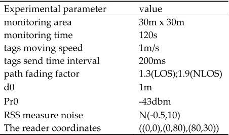
The proposed algorithm was simulated and parameter settings are listed in table 1. According to the figure 1, three of the readers were arranged at coordinates ((0, 0), (0, 80), (80, 30)). The monitoring area size was 30mx30m, and the unknown tag moved at an average speed of 1 m/s, moving from LOS environment into NLOS environment and moving from NLOS into LOS environment. The data sending time interval for RFID tags is 200 ms.
Table 1. Experimental Environment Parameter Settings Experimental parameter value
monitoring area 30m x 30m
monitoring time 120s
tags moving speed 1m/s
tags send time interval 200ms
path fading factor 1.3(LOS);1.9(NLOS)
d0 1m Pr0 -43dbm RSS measure noise N(-0.5,10)
The reader coordinates ((0,0),(0,80),(80,30))
Figure 6. The figure shows the comparison of the location estimation about the path loss detection. The left figure depicts the estimation trajectory without path loss detection, and the right figure depicts the estimation trajectory with path loss detection.
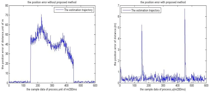
Figure 7. The figure shows the comparison of position error between the proposed method and without the proposed method. The left figure is the position error depiction without the proposed method. The right figure depicts the position error with proposed method. It is shown that the proposed method have a good performance in LOS/NLOS hybrid environment.
7. Experiment
7.1 Experiment setup
Figure 8. PuDong research center floor plan illustrating readers and walking trajectory of tags carriers. The red trajectory is where the tag carrier walked through.
Figure 9. Indoor test environment, tag and reader. The tag is installed on the waist of pedestrian and the readers are mounted on tripods.
7.2 Tests and Results
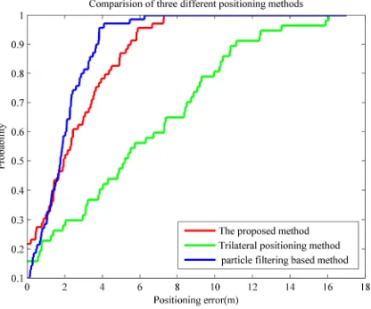
As shown in the figure 10, the accuracy of trilateral positioning method is worst among three methods. The precision of the particle filter based positioning method is best among three methods. The precision of proposed method was slightly poorer than particle filter based positioning method.
Figure 10. The cumulative distribution functions of three different positioning methods. 8. Conclusion and Discussion
The paper proposes an IMU-aided NLOS error mitigation method for RFID based indoor positioning. The method uses the ratio of processed RSS and relative displacement of tag movement to find the singular points of path loss parameter, and identifies the NLOS and LOS through the singular points. Then the CRLB of the proposed method is calculated and it is concluded theoretically that the use of IMU into the RSS localization method is superior to the effect of only use RSS for positioning.
Then the experiment was carried out and a comparison was made with other two positioning methods. In the proposed method, the NLOS error mitigation is used to distinguish the hall and room, so different readers are used for localization when tags carriers are in different positions. In this way, the positioning accuracy for proposed method is far better than trilateral positioning method. Although the positioning accuracy of particle filter based method is slightly better than the proposed method, it needs a lot of site survey for map generation and the use of particle filter is time-consuming. In conclusion, the proposed method is better than other two methods in practical applications.
The paper has put forward a method to distinguish between LOS and NLOS to mitigate the NLOS error. In the future study, we will focus on distinguishing between different NLOS environments with the aid of IMU and RSS.
Acknowledgments: This work has been supported by Science and Technology Commission of Shanghai Municipality [Grant No.17511106902], Postgraduate Student Scientific Research Innovation Projects [Grant No. ykc17076].
References
1. K. Domdouzis, B.; Kumar, C.; Anumba, Radio-Frequency Identification (RFID) applications: a brief introduction, Adv. Eng. Inform. 21 (4) (2007) 350–355.
2. Huang C H; Lee L H; Ho C C, et al. Real-Time RFID Indoor Positioning System Based on Kalman-Filter Drift Removal and Heron-Bilateration Location Estimation[J]. IEEE Transactions on Instrumentation & Measurement, 2015, 64(3):728-739.
3. Savochkin D A. Simple approach for passive RFID-based trilateration without offline training stage[C]// IEEE Rfid Technology and Applications. 2014:159-164.
4. Lee B; Woo D M; Park M K, et al. Development of self-localizer using collaboration of trilateration and triangulation[C]// International Conference on Fuzzy Systems and Knowledge Discovery. IEEE, 2014:729-733.
5. Belhadi, Z.; Fergani, L. Fingerprinting methods for RFID tag indoor localization[C]// International Conference on Multimedia Computing and Systems. IEEE, 2014:717-722.
6. Retscher Q F G. Active RFID Trilateration and Location Fingerprinting Based on RSSI for Pedestrian Navigation[J]. Journal of Navigation, 2009, 62(2):323-340.
7. Zou B.; Huang B H.; Zhang H. RFID fingerprints-based localization based on different similarity measures[J]. Application Research of Computers, 2014.
8. Bertoncini C.; Rudd K.; Nousain B, et al. Wavelet Fingerprinting of Radio-Frequency Identification (RFID) Tags[J]. IEEE Transactions on Industrial Electronics, 2012, 59(12):4843-4850.
9. P. Chen, “A non-line-of-sight error mitigation algorithm in location estimation,” in Proc. IEEE WCNC, 1999, pp. 316–320.
10. X. Li, “An iterative NLOS mitigation algorithm for location estimation in sensor networks,” in Proc. 15th IST Mobile Wireless Commun. Summit, Miconos, Greece, 2006, pp. 1–5.
11. I. Guvenc, C. Chong, and F. Watanabe, “NLOS identification and mitigation for UWB localization systems,” in Proc. IEEE WCNC, 2007,pp. 1571–1576.
12. S. Nawaz and N. Trigoni, “Convex programming based robust localization in NLOS prone cluttered environments,” in Proc. 10th Int. Conf. IPSN,Chicago, IL, USA, 2011, pp. 318–329.
13. Nawaz S.; Trigoni N. Robust localization in cluttered environments with NLOS propagation[J]. 2010:166-175.
14. 14Yang Y.; Zhao Y.; Kyas M. A statistics-based least squares (SLS) method for non-line-of-sight error of indoor localization[J]. 2013:2299-2304.
15. Wylie M P.; Holtzman J. The non-line of sight problem in mobile location estimation[J]. 1996 5th IEEE International Conference on Universal Personal Communications, 1996, vol.2: 827-831.
16. I. Guven. C.-C. Chong; F. Watanabe; and H. Inamura, “Nlos identification and weighted least-squares localization for uwb systems using multipath channel statistics,” EURASIP J. Adv. Signal Process, vol. 2008, p. 36, 2008.
17. S.Venkatesh; R. M. Buehrer, “Non-line-of-sight identification in ultra wideband systems based on received signal statistics,” IET Microw. Antennas Propag., vol. 1, no. 6, pp. 1120–1130, Dec. 2007.
18. Y. Jo, J. Lee; D. Ha; S. Kang, “Accuracy enhancement for UWB indoor positioning using ray tracing,” in Proc. IEEE/ION Position. Loc.Navigat. Symp., 2006, pp. 565–568.
19. J. Khodjaev; Y. Park; A. Saeed Malik, “Survey of NLOS identification and error mitigation problems in UWB-based positioning algorithms for dense environments,” Ann. Telecomm., vol. 65, no. 5/6, pp. 301–311, Jun. 2010.
20. S. Maran; W. M. Gifford; H. Wymeersch, “NLOS identification and mitigation for localization based on UWB experimental data,” IEEE J. Sel. Areas Commun., vol. 28, no. 7, pp. 1026–1035, Sep. 2010.
21. K. Yu; Y. J. Guo; S. Member, “Statistical NLOS identification based on AOA, TOA, and signal strength,” IEEE Trans. Veh. Technol., vol. 58, no. 1, pp. 274–286, Jan. 2009.
22. Vila-Valls, J; Closas, P NLOS mitigation in indoor localization by marginalized Monte Carlo Gaussian smoothing,EURASIP JOURNAL ON ADVANCES IN SIGNAL PROCESSING,AUG. 2017
23. Gao S; Zhang F; Wang G. NLOS Error Mitigation for TOA-Based Source Localization With Unknown Transmission Time[J]. IEEE Sensors Journal, 2017, PP(99):1-1.
24. Wu J; Zhao T; Li S; et al. Belief Interval of Dempster-Shafer Theory for Line-of-Sight Identification in Indoor Positioning Applications.[J]. Sensors, 2017, 17(6).
26. Chen C H; Feng K T. Statistical Distance Estimation Algorithms with RSS Measurements for Indoor LTE-A Networks[J]. IEEE Transactions on Vehicular Technology, 2017, PP(99):1-1.
27. E. Foxlin, “Pedestrian tracking with shoe-mounted inertial sensors,” Comput. Graph. Appl., vol. 25, no. 6, pp. 38–46, Nov.–Dec. 2005.
28. A. Jiménez; F. Seco; J. Prieto and J. Guevara, “Indoor pedestrian navigation using an INS/EKF framework for Yaw drift reduction and foot mounted IMU,” in Proc. 7th WPNC, 2010, vol. 10, pp. 135–143.