Maximum Power Point Tracking Algorithm
for PV Systems using Partially Shaded
Conditions
*
Sheshmani Tripathi, Dr. V. K. Jain
*
M. Tech. Scholar, Department of Electrical and Electronics Engineering, Bhopal Institute of Technology,
Bhopal, India
Department of Electrical and Electronics Engineering, Bhopal Institute of Technology, Bhopal, India
ABSTRACT: The performance of a photovoltaic (PV) array is affected by temperature, solar insulation, shading, and array configuration. Often, the PV arrays get shadowed, completely or partially, by the passing clouds, neighboring buildings and towers, trees, and utility and telephone poles. Under partially shaded conditions, the PV characteristics get more complex with multiple peaks. This makes the tracking of the actual maximum power point (MPP) a difficult task. In this paper, a simple technique of MPPT is presented for photovoltaic power generation system to solve the aforementioned problems. It realizes simple control system to track the real maximum power point even under non-uniform or for rapidly changing insulation conditions. The proposed technique in the first stage searches the I-V characteristic of the PV arrays by scanning the whole range. Simulation and some selected experimental results are presented to prove the feasibility of the proposed technique.
KEYWORDS: Photovoltaic (PV) array, MATLAB Simulink, Maximum Power Point Tracking (MPPT)
I. INTRODUCTION
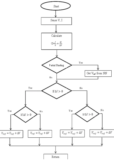
paper, we propose a simple and practical approach for commercial base use. This method is based on two stages; in the first stage the controller searches the I-V characteristic of the PV regularly at certain specified time using large value of step of the P&O method with storing the actual maximum power point and its corresponding duty cycle. As this obtained MPPT point is not the exact one due to the used large step, a second stage of the controller is designed to oscillate around the obtained MPP point by using the conventional P&O algorithm with a small step. In another word, the algorithm during the first stage operates with large step to reduce the scanning time of the I-V characteristic curve, then after obtaining the approximated MPP, the algorithm oscillates around this MPP with a small step (delta) to provide the exact point with a small oscillation.
As mentioned above, electrical characteristics of PV module are affected by environmental conditions such as temperature, solar irradiation dusts accumulation and shadow caused by bird’s clouds and so on. To study the effects of the previous environmental factors a MATLAB model was proposed the model takes into accounts most of the environmental conditions that affect the electrical characteristics of the PV.
The paper continues as follows: Section II discuss the mathematical model of PV. In Section III, the proposed MPPT algorithm is described. In section IV, the implementation and the experimental results are described. Finally, conclusions are presented in section V.
II. CHARACTERISTICS OF PV SYSTEM
The photovoltaic cell converts the light energy intoelectrical energy depending on the irradiation of the sun andtemperature in the atmosphere. Basically PVC is a PNjunction diode [3] [4]. But in PN junction diode DCI ACsource is needed to work, but here light energy is used as asource to produce DC output. PVC is a current control sourcenot a voltage control source. The equivalent electrical circuitdiagram of PVC is shown in the Figure 2.
] 1 /
) [exp(
0
I V IR KT
ID S (1)
Therefore PVC output current is given in equation 2.
Sh D
L I I
I
I (2)
Sh S S L R IR V KT IR V q I I I / ) ( ] 1 / )) ( [exp( 0
(3)
Where
I
Dthe diode is current,R
sh is the shunt resistance,I
Lis the light generated current of solar array.Solar cell is basically a p-n junction fabricated in a thin wafer or layer of semiconductor. The electromagnetic radiation of solar energy can be directly converted electricity through photovoltaic effect. Being exposed to the sunlight, photons with energy greater than the band-gap energy of the semiconductor are absorbed and create some electron-hole pairs proportional to the incident irradiation. Under the influence of the internal electric fields of the p-n junction, these carriers are swept apart and create a photocurrent which is directly proportional to solar insolation. PV system naturally exhibits a nonlinear I-V and P-V characteristics which vary with the radiant intensity and cell temperature.III. MPPT ALGORITHM USING PARTIALLY SHADED CONDITION
Figure 5 indicates the characteristic output power curve for the solar cell from simulation under a given temperature and irradiance. MPPT control has been proposed and implemented for extracting the maximum power from the PV cell. PV array voltage (i.e. incrementing or decreasing) and comparing the PV output power with that of the previous perturbation cycle. If the perturbation leads to an increase/decrease in array power, the subsequent perturbation is made in the same/opposite direction. In this manner, the peak power is tracked continuously. But this algorithm has two weaknesses.
When shading occurs, the reversal of the voltage can be observed in that specific section and now the bypass diode in parallel will conduct the current. The results are:
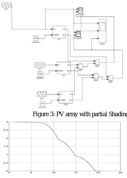
Figure 3: PV array with partial Shading
The current of the un-shaded section flows through the bypass diode and the power/voltage characteristic shows a second local maximum
The shaded cell is only loaded with that fraction of power produced by the remaining unshaded cells of that section
When the number of cells which are bridged by the by-pass diode is not too high, the level of the breakthrough voltage will not be reached.
But there are also some draw backs resulting from the by-pass diodes:Higher cost for the module production and assembly problems of the by-pass diodes. Losses in the by-pass diode in the case of shading.
The PV module is connected to a variable DC voltage source for measuring its I-V and P-V characteristics. It is modeled as three strings of 20 series-connected cells in parallel with bypass diodes that allow current flow when cells are shaded or damaged. Standard irradiance of 1000 W/m2 is applied on the first string of 20 cells while partial shading is applied on strings 2 (cells 21-40) and string 3 (cells 41-60), resulting in respective irradiances of 300 W/m2 and 600 W/m2.Simulate the model. The global I-V and P-V characteristics are plotted at the end of simulation.
Note that the P-V curve exhibits three maxima. When this PV module is connected to a voltage-sourced converter, this may be challenging for the Maximum Power Point Tracking (MPPT) algorithm to converge on the highest peak. The Global Maximum Power Point (GMPP) (Pm= 104 W) indicated by a red circle on the figure is 34% lower than the expected maximum power (250/3*(1 +0.3 +0.6) = 158 W).
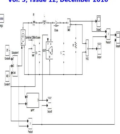
Figure 6: Simulink model for partial shading of MPPT algorithm
IV. CONCLUSION
In this paper, a simple technique of maximum power generation systems based on partial to realize a simple control system to track the real maximum power point even under non-uniform or for rapidly changing insulation conditions. The proposed technique in the first stage implements a survey for the I-V characteristic of the PV arrays to detect an approximated MPP.
A MATLAB-Simulink based PV module model is presented in this paper, which includes a controlled current source. Various PV array simulation schematic could be created by the proposed model, and parameters of irradiance and temperature of each PV module model can be set independently. The PV array simulation model allows us to investigate the characteristics of a PV array under various conditions of different irradiance and temperature, especially under condition of partially shading.
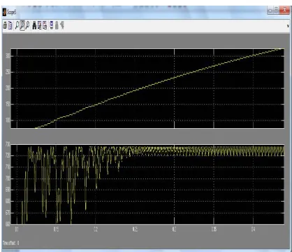
Figure 8: Response of the switching frequency of the PV array
REFERENCES
1. T. Noguchi, S. Togashi, and R. Nakamoto, “Short-current pulse-based maximum-power-point tracking method for multiple photovoltaic and converter module system,” IEEE Trans. Ind. Electron., vol. 49, no. 1, pp. 217–223, Feb. 2002.
2. Kun Ding, XinGao Bian, HaiHao Liu, and Tao Peng, “A MATLAB-Simulink-Based PV Module Model and Its Application Under Conditions
of Nonuniform Irradiance”, IEEE Transactions on Energy Conversion, Vol. 27, No. 4, December 2012.
3. V. Salas, E. Olias, A. Barrado, and A. Lazaro, “Review of the maximum power point tracking algorithms for stand-alone photovoltaic systems,” Sol. Energy Mater. Sol. Cells, vol. 90, no. 11, pp. 1555–1578, Jul. 2006.
4. C. Hua, J. Lin, and C. Chen, “Implementation of a DSPcontrolled photovoltaic system with peak power tracking,” IEEETrans. Ind. Electron., vol. 45, no. 1, pp. 99–107, Feb. 1998.
5. N. Fernia, G. Petrone, G. Spagnuolo, andM. Vitelli, “Optimization of perturb and observe maximum power point tracking method,” IEEETrans. Power Electron., vol. 20, no. 4, pp. 963–973, Jul. 2005.
6. T. Esram, J. W. Kimball, P. T. Krein, P. L. Chapman, and P. Midya, “Dynamic maximum power point tracking of photovoltaic arrays using ripple correlation control,” IEEE Trans. Power Electron., vol. 21, no. 5, pp. 1282–1291, Sep. 2006.
7. C. Dorofte, U. Borup, and F. Blaabjerg, “A combined two-method MPPT control scheme for grid-connected photovoltaic systems,” in Proc. Eur. Conf. Power Electron. Appl., Sep. 11–14, 2005, pp. 1–10.
8. K. H. Hussein and I. Muta, “Maximum photovoltaic power tracking: An algorithm for rapidly changing atmospheric conditions,” Proc.Inst. Electr. Eng.—Generation, Transmission Distribution, vol. 142, no. 1, pp. 59–64,Jan. 1995.
9. D. Sera, T. Kerekes, R. Teodorescu, and F. Blaabjerg, “Improved MPPT method for rapidly changing environmental conditions,” in Proc. IEEE Int. Ind. Electron. Symp., Jul. 2006, vol. 2, pp. 1420–1425.
10. N. Kasa, T. Iida, and H. Iwamoto, “Maximum power point tracking with capacitor identifier for photovoltaic power system,” Proc. Inst.Electr. Eng.—Electr. Power Appl., vol. 147, no. 6, pp. 497–502, Nov. 2000.
11. N. Kasa, T. Iida, and L. Chen, “Flyback inverter controlled by sensorless current MPPT for photovoltaic power system,” IEEETrans. Ind. Electron., vol. 52, no. 4, pp. 1145–1152, Aug. 2005.