ISSN(Online) : 2319-8753 ISSN (Print) : 2347-6710
I
nternational
J
ournal of
I
nnovative
R
esearch in
S
cience,
E
ngineering and
T
echnology
(An ISO 3297: 2007 Certified Organization)
Vol. 5, Issue 4, April 2016
Finite Element Method for Analysing the
Temperature Acting on Cutting Tool
Sasikumar.V1, Mr.C.K.Murugesan 2
PG Scholar, Department of Mechanical Engineering, Mahendra Engineering College, Mahendrapuri, Namakkal, India1
Assistant Professor, Department of Mechanical Engineering, Mahendra Engineering College, Mahendrapuri,
Namakkal, India2
ABSTRACT: The overall objective of this study was to analyze the temperature acting on cutting tool by finite element method. A machining tool must be able to combine high hardness with high fracture strength at elevated temperature. A high thermal conductivity is also a desired tool property since it will reduce the tendency to local thermal softening.
The term tool bit generally refers to a non-rotary cutting tool used in metal lathes, shapers, and planers. Such cutters are also often referred to by the set-phrase name of single-point cutting tool. The cutting edge is ground to suit a particular machining operation and may be re sharpened or re shaped as needed. The ground tool bit is held rigidly by a tool holder while it is cutting.
Originally, all tool bits were made of high carbon tool steels with the appropriate hardening and tempering. Since the introductions of high-speed steel (HSS), sintered carbide, ceramic and diamond cutters, those materials have gradually replaced the earlier kinds of tool steel in almost all cutting applications. Most tool bits today are made of HSS, cobalt steel, or carbide
The simulation part will be carried out using the Analysis software, Ansys. The model is exported to ANSYS by converting it to IGES format. The imported model is meshed in ANSYS and boundary constrains are defined. With the Boundary constrains, the stresses and strain of the component can be determined and the values are tabulated. Thus the investigation of stress and strain is carried out using ANSYS. This project will also help to learn modeling software and also ANSYS.
1. INTRODUCTION
ISSN(Online) : 2319-8753 ISSN (Print) : 2347-6710
I
nternational
J
ournal of
I
nnovative
R
esearch in
S
cience,
E
ngineering and
T
echnology
(An ISO 3297: 2007 Certified Organization)
Vol. 5, Issue 4, April 2016
II. OBJECTIVE OF THESIS
• 3D model of the structure created using pro e, then the model and perform structural and thermal analyses of the cutting tool with loading conditions such as force, temperature etc., on the appropriate portions. The finite element software ANSYS 14.5 is used for the analyses.
• To analyze cutting tool by high carbon steel and high speed steel materials in ansys workbench. Then the results of deformation, stress, strain and temperature distribution values are getting from ansys finite element method to find suitable material for cutting tool.
III. NEED OF THESIS
The need for doing this project was primarily an interest in undertaking a challenging project in an interesting area of research. Cutting tool is one of the key components of the manufacturing process and it’s working the hard condition. Here the material of the cutting tool is analyzed with two materials to improve our innovation and this project carried out by us will make an impressing mark in the industrial field.
IV. METHODOLOGY
MODELING
The cutting tool model has been entirely modeled by PRO E software. First of all sketch command of the pro e is opened. Then by using 2d commands sketch is created. Then 3D model of cutting tool created by using extrude command.
TRANSFORMATION OF MODEL
Then the model is converted in to the IGES format which is most suitable and easy access for any other software’s.
Using the IGES format we can import the cutting tool model from PRO-ENGINEER to ANSYS. Now we can make structural and thermal analysis.
MESHING
ISSN(Online) : 2319-8753 ISSN (Print) : 2347-6710
I
nternational
J
ournal of
I
nnovative
R
esearch in
S
cience,
E
ngineering and
T
echnology
(An ISO 3297: 2007 Certified Organization)
Vol. 5, Issue 4, April 2016
LOADING
The types of loading that can be applied in a structural and analysis include: Externally applied forces and pressures
Steady-state inertial forces (such as gravity or rotational velocity) Temperature
ANALYSIS
A static structural analysis determines the displacements, stresses, strains, and forces in structures or components caused by loads that do not induce significant inertia and damping effects. Steady loading and response conditions are assumed; that is, the loads and the cutting tool model's response are assumed to vary slowly with respect to time.
Transient thermal analysis determines temperatures and other thermal quantities that vary over time. Engineers commonly use temperatures that a transient thermal analysis calculates as input to structural analyses for thermal stress evaluations.
V. MATERIAL PROPERTIES
PRO-E
Pro/ENGINEER, PTC's parametric, integrated 3D CAD/CAM/CAE solution, is used by discrete manufacturers for mechanical engineering, design and manufacturing.
ISSN(Online) : 2319-8753 ISSN (Print) : 2347-6710
I
nternational
J
ournal of
I
nnovative
R
esearch in
S
cience,
E
ngineering and
T
echnology
(An ISO 3297: 2007 Certified Organization)
Vol. 5, Issue 4, April 2016
include Solid Modeling, Surfacing, Rendering, Data Interoperability, Routed Systems Design, Simulation, Tolerance Analysis, and NC and Tooling Design.
All data is associative and interchangeable between the CAD, CAE and CAM modules without conversion. A product and its entire bill of materials (BOM) can be modeled accurately with fully associative engineering drawings, and revision control information. The associativity in Pro/ENGINEER enables users to make changes in the design at any time during the product development process and automatically update downstream deliverables.
PRO-E DRAWINGS
Fig 1: 2D sketch for single point cutting tool
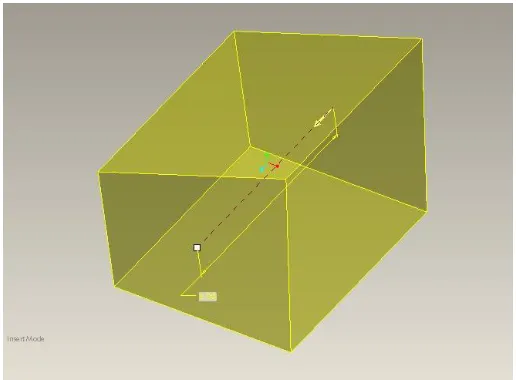
Fig 2: Extruded model of single point cutting tool
ANSYS
ISSN(Online) : 2319-8753 ISSN (Print) : 2347-6710
I
nternational
J
ournal of
I
nnovative
R
esearch in
S
cience,
E
ngineering and
T
echnology
(An ISO 3297: 2007 Certified Organization)
Vol. 5, Issue 4, April 2016
ANSYS Mechanical and ANSYS Multiphysics software are non exportable analysis tools incorporating pre-processing (geometry creation, meshing), solver and post-pre-processing modules in a graphical user interface. These are general-purpose finite element modeling packages for numerically solving mechanical problems, including static/dynamic structural analysis (both linear and non-linear), heat transfer and fluid problems, as well as acoustic and electro-magnetic problems.
ANSYS Mechanical technology incorporates both structural and material non-linearities. ANSYS Multiphysics software includes solvers for thermal, structural, CFD, electromagnetics, and acoustics and can sometimes couple these separate physics together in order to address multidisciplinary applications. ANSYS software can also be used in civil engineering, electrical engineering, physics and chemistry.
ANSYS, Inc. acquired the CFX computational fluid dynamics code in 2003 and Fluent, Inc. in 2006. The CFD packages from ANSYS are used for engineering simulations. In 2008, ANSYS acquired Ansoft Corporation, a leading developer of high-performance electronic design automation (EDA) software, and added a suite of products designed to simulate high-performance electronics designs found in mobile communication and Internet devices, broadband networking components and systems, integrated circuits, printed circuit boards, and electromechanical systems. The acquisition allowed ANSYS to address the continuing convergence of the mechanical and electrical worlds across a whole range of industry sectors.
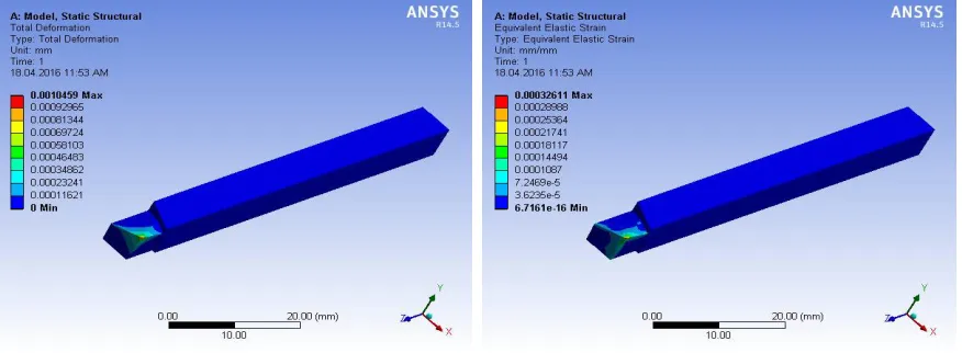
VI. RESULTS
Fig 3: TOTAL DEFORMATION
STATIC STRUCTURAL RESULTS AND COMPARISON OF ABOVE MATERIALS
S.
NO. PARTICULARS
TOTAL DEFORMATION
(mm)
EQUIVALENT ELASTIC
STRAIN (mm/mm)
EQUIVALENT STRESS
(MPa)
1 HIGH SPEED
STEEL (HSS) 0.001045 0.00032611 72.071
2 CARBON
STEEL
0.001151 0.00036034 72.067
ISSN(Online) : 2319-8753 ISSN (Print) : 2347-6710
I
nternational
J
ournal of
I
nnovative
R
esearch in
S
cience,
E
ngineering and
T
echnology
(An ISO 3297: 2007 Certified Organization)
Vol. 5, Issue 4, April 2016
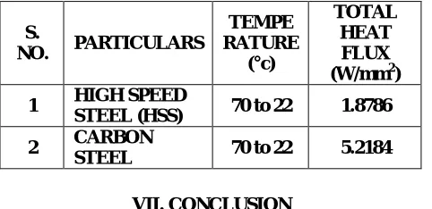
TRANSIENT THERMAL RESULTS AND COMPARISON OF ABOVE MATERIALS
VII. CONCLUSION
Experimental results from testing the single point cutting tool under force and temperature are listed in the Table. Analysis has been carried out for two different materials such as high speed steel and carbon steel. The results for static structural such as total deformation, equivalent elastic strain and equivalent stress for each material and in transient thermal such as temperature, total heat flux and directional heat flux are determined. Comparing the two materials, high speed steel material has the low values of total deformation and in transient thermal analysis total heat flux values is less. Hence it is concluded that high speed steel material is suitable for the single point cutting tool.
The project carried out by us will make an impressing mark in the field of machine shop.
While carrying out this project we are able to study about the 3Dmodelling software (PRO-E) and Study about the analyzing software (ansys) to develop our basic knowledge to know about the industrial design.
REFERENCES
[1] Machine design, R S Khurmi, 2003 edition, Pg No’s:701-741
[2] Theory and Design of Automotive Engines - B Dinesh Prabhu, Assistant Professor, P E S College of Engineering, Mandya, Karnataka [3] Design Data Book – PSG Tech
[4] http://www.carfolio.com/ - For Ambassador Car specifications
[5] COMPOSITE MATERIALS DESIGN AND APPLICATIONS, Daniel Gay, Suong V. Hoa, Stephen W. Tsai.
S.
NO. PARTICULARS
TEMPE RATURE
(°c)
TOTAL HEAT FLUX (W/mm2)
1 HIGH SPEED
STEEL (HSS) 70 to 22 1.8786
2 CARBON