Controlling The Block Coefficient Of Ship Hull Stability To
Optimize The Ship Hull Design Using Fluid Dynamic Analysis
1
Pothuganti Ramesh, 2Charan 1,2
Branch: Machine Design
1
P.G. Scholar, 2Guide, Assistant Professor
1,2
Githanjali Engineering &Technology
EMAIL ID: [email protected], [email protected]
Abstract:
Ship hull is water tight body which plays a major role in ship’s effective transport system. Ship hull structure design has recently become more and more important topic. Whole structure of ship hull to be considered, technically and economically. It is a very important part in ship management industry because total strength of ship design and cost, 20% is only for making ship hull structure design. Output of ship’s main engine is increased with less vibration in rigid propeller along with accurate hull structure design. Ship hull structure design accurate when hull consist of optimized block coefficient. So here need to control the block coefficient of ship hull is considered as very important one. Previously more topics published on vibration controlling on propeller shafts and developing the design of surface of ship hull. Among the all works, this work is mainly researched on controlling the block coefficient (Not less, Not more) using different shapes of ship hull.
Block coefficient is the ratio of the volume of the displacement of a ship to that of a rectangular block having the same length, breadth, and draft. The main aim of this project was to develop the accurate shape of ship hull with optimized block coefficient. Design of different shapes of ship hulls are done using unigraphics software. Ansys software is used to develop the flow analysis of ship hulls. From analysis results, block coefficient is calculated for all ship
hulls and best one is proposed from block coefficient results.
INTRODUCTION 1.1 SHIP HULL
The hull is the watertight body of a ship or boat. Atop the hull may be a deckhouse or some other form of superstructure, like a mast. The line where the hull meets the water surface is called the waterline.
The structure of the hull varies depending on the vessel type. In a typical modern steel ship, the structure consists of watertight and non-tight decks, major transverse and watertight (and also sometimes non-tight or longitudinal) members called bulkheads, intermediate members such as girders, stringers and webs, and minor members called ordinary transverse frames, frames, or longitudinals, depending on the structural arrangement. The uppermost continuous deck may be called the "upper deck", "weather deck", "spar deck", "main deck", or simply "deck". The particular name given depends on the context—the type of qqship or boat, the arrangement, or even where it sails. Not all hulls are decked (for instance a dinghy).
vessels to some extent, or be of a monocoque arrangement. In many cases, composite hulls are built by sandwiching thin fiber-reinforced skins over a lightweight but reasonably rigid core of foam, balsa wood, impregnated paper honeycomb or other material.
UNIGRAPHICS INTRODUCTION NX, also known as NX unigraphics or usually just u-g, is an advanced CAD/CAM/CAE software package developed by Siemens PLM software. It is used, among other tasks, for:
Design (parametric and direct solid/surface modelling)
Engineering analysis (static, dynamic, electro-magnetic, thermal, using the finite element method, and fluid using the finite volume method).
Manufacturing finished design by using included machining modules
First release of the new "next generation" version of unigraphics and ideas, called NX. this will eventually bring the functionality and capabilities of both unigraphics and ideas together into a single consolidated product.
Increasing complexity of products, development processes and design teams is challenging companies to find new tools and methods to deliver greater innovation and higher quality at lower cost. leading-edge technology from Siemens PLM software delivers greater power for today’s design challenge. from innovative synchronous technology that unites parametric and history-free modeling, to NX active mockup for multi-cad assembly design, NX delivers breakthrough technology that sets new standards for speed, performance, and ease of use.
NX automates and simplifies design by leveraging the product and process knowledge that companies gain from experience and from industry best practices.
it includes tools that designers can use to capture knowledge to automated repetitive tasks. the result is reduced cost and cycle time and improved quality.
Overview of Solid Modeling:
The Unigraphics NX Modeling application provides a solid modeling system to enable rapid conceptual design. Engineers can incorporate their requirements and design restrictions by defining mathematical relationships between different parts of the design.
Design engineers can quickly perform conceptual and detailed designs using the Modeling feature and constraint based solid modeller. They can create and edit complex, realistic, solid models interactively, and with far less effort than more traditional wire frame and solid based systems. Feature Based solid modeling and editing capabilities allow designers to change and update solid bodies by directly editing the dimensions of a solid feature and/or by using other geometric editing and construction techniques.
Introduction to Drafting:
The Drafting application is designed to allow you to create and maintain a variety of drawings made from models generated from within the Modeling application. Drawings created in the Drafting application are fully associative to the model. Any changes made to the model are automatically reflected in the drawing. This Associatively allows you to make as many model changes as you wish. Besides the powerful Associativity functionality, Drafting contains many other useful features including the following:
productivity.Support of new assembly architecture and concurrent engineering. This allows the drafter to make drawings at the same time as the designer works on the model. The capability to create fully associative cross-sectional views with automatic hidden line rendering and crosshatching. Automatic orthographic view alignment. This allows you to quickly place views on a drawing, without having to consider their alignment. Automatic hidden line rendering of drawing views. The ability to edit most drafting objects (e.g., dimensions, symbols, etc.) from the graphics window. This allows you to create drafting objects and make changes to them immediately. On-screen feedback during the drafting process to reduce rework and editing. User controls for drawing updates, which enhance user productivity. Finally, you can add form features, such as chamfers, holes, slots, or even user defined features to complete the object.
Assemblies concepts: Components:
Assembly part files point to geometry and features in the subordinate parts rather than creating duplicate copies of those objects at each level in the assembly. This technique not only minimizes the size of assembly parts files, but also provides high levels of Associativity. For example, modifying the geometry of one component causes all assemblies that use that component in the session to automatically reflect that change. Some properties, such as translucency and partial shading (on the Edit Object Display dialog), can be changed directly on a selected component. Other properties are changed on selected solids or geometry within a component. Within an assembly, a particular part may be used in many places. Each usage is referred to as a component and the file containing the actual geometry for the component is called the component part.
Top-down or Bottom-up Modeling:
You are not limited to any one particular approach to building the assembly. You can create individual models in isolation, and then later add them to assemblies (bottom-up), or you can create them directly at the assembly level (top-down). For example, you can initially work in a top-down fashion, and then switch back and forth between bottom-up and top-down modeling.
Design in Context:
When the displayed part is an assembly, it is possible to change the work part to any of the components within that assembly (except for unloaded parts and parts of different units). Geometry features, and components can then be added to or edited within the work part. Geometry outside of the work part can be referenced in many modeling operations. For example, control points on geometry outside of the work part can be used to position a feature within the work part. When an object is designed in context, it is added to the reference set used to represent the work part.
Associativity Maintained:
Geometric changes made at any level within an assembly result in the update of associated data at all other levels of affected assemblies. An edit to an individual piece part causes all assembly drawings that use that part to be updated appropriately. Conversely, an edit made to a component in the context of an assembly results in the update of drawings and other associated objects (such as tool paths) within the component part. See the next two figures for examples of top-down and bottom-up updates.
Mating Conditions:
that a cylindrical face on one component is to be coaxial with a conical face on another component. You can use combinations of different constraints to completely specify a component's position in the assembly. The system considers one of the components as fixed in a constant location, then calculates a position for the other component which satisfies the specified constraints. The relationship between the two components is associative. If you move the fixed component's location, the component that is mated to it also moves when you update. For example, if you mate a bolt to a hole, if the hole is moved, the bolt moves with it.
Using Reference Sets to Reduce the Graphic Display:
Large, complex assemblies can be simplified graphically by filtering the amount of data that is used to represent a given component or subassembly by using reference sets. Reference sets can be used to drastically reduce (or even totally eliminate) the graphical representation of portions of the assembly without modifying the actual assembly structure or underlying geometric models. Each component can use a different reference set, thus allowing different representations of the same part within a single assembly. The figure below shows an example of a bushing component used twice in an assembly, each displayed with a different reference set. When you open an assembly, it is automatically updated to reflect the latest versions of all components it uses. Load Options lets you control the extent to which changes made by other users affect your assemblies. Drawings of assemblies are created in much the same way as piece part drawings. You can attach dimensions, ID symbols and other drafting objects to component geometry. A parts list is a table summarizing the quantities and attributes of components used in the current assembly. You can add a parts list to the assembly drawing along with associated callout symbols, all of which are updated as the
assembly structure is modified. See the following figure.
Machining of Assemblies:
Assembly parts may be machined using the Manufacturing applications. An assembly can be created containing all of the setup, such as fixtures, necessary to machine a particular part. This approach has several advantages over traditional methods:
It avoids having to merge the fixture geometry into the part to be machined.
It lets the NC programmer generate fully associative tool paths for models for which the programmer may not have write access privilege.
It enables multiple NC programmers to develop NC data in separate files simultaneously
DESIGNING OF SHIP HULL
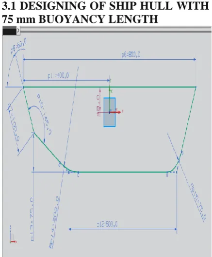
3.1 DESIGNING OF SHIP HULL WITH 75 mm BUOYANCY LENGTH
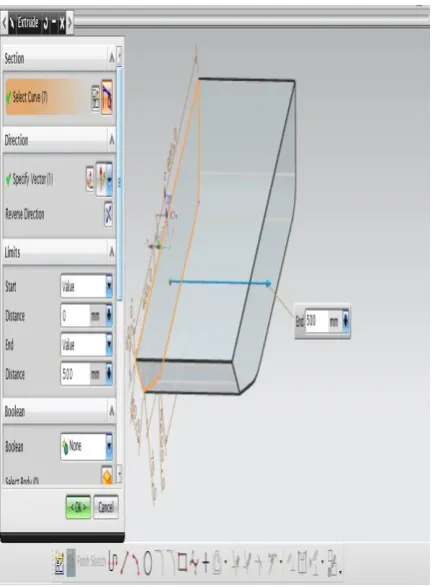
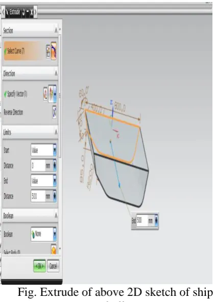
Fig. Extrude of above 2D sketch of ship hull
Fig. Shell option for making hollow ship hull
Fig. Final model of ship hull
DESIGNING OF SHIP HULL WITH 85 mm BUOYANCY LENGTH.
Fig. Extrude of above 2D sketch of ship hull
Fig. Shell option for making hollow ship hull
Fig. Final model of ship hull
ANALYSIS OF SHIP HULL USING ANSYS
4.1 INTRODUCTION ABOUT FEM The Basic concept in FEM is that the body or structure may be divided into smaller elements of finite dimensions called “Finite Elements”. The original body or the structure is then considered as an assemblage of these elements connected at a finite number of joints called “Nodes” or “Nodal Points”. Simple functions are chosen to approximate the displacements over each finite element. Such assumed functions are called “shape functions”. This will represent the displacement within the element in terms of the displacement at the nodes of the element.
Due to high cost of computing power of years gone by, FEM has a history of being used to solve complex and cost critical problems. Classical methods alone usually cannot provide adequate information to determine the safe working limits of a major civil engineering construction or an automobile or an aircraft. In the recent years, FEM has been universally used to solve structural engineering problems. The departments, which are heavily relied on this technology, are the automotive and aerospace industry. Due to the need to meet the extreme demands for faster, stronger, efficient and lightweight automobiles and aircraft, manufacturers have to rely on this technique to stay competitive.
FEA has been used routinely in high volume production and manufacturing industries for many years, as to get a product design wrong would be detrimental. For example, if a large manufacturer had to recall one model alone due to a hand brake design fault, they would end up having to replace up to few millions of hand brakes. This will cause a heavier loss to the company.
Nowadays, even the most simple of products rely on the finite element method for design evaluation. This is because contemporary design problems usually cannot be solved as accurately & cheaply using any other method that is currently available. Physical testing was the norm in the years gone by, but now it is simply too expensive and time consuming also.
Basic Concepts: The Finite Element Method is based on the idea of building a complicated object with simple blocks, or, dividing a complicated object into small and manageable pieces. Application of this simple idea can be found everywhere in everyday life as well as engineering. The philosophy of FEA can be explained with a small example such as measuring the area of a circle.
Area of one Triangle: Si = ½ * R2* Sin I Area of the Circle: SN = ½ * R2 * N * Sin (2 / N) R2 as N
Where N = total number of triangles (elements)
If one needs to evaluate the area of the circle without using the conventional formula, one of the approaches could be to divide the above area into a number of equal segments. The area of each triangle multiplied by the number of such segments gives the total area of the circle.
Brief history of the fem: Who
The reference credited is to Courant (Mathematician), Turner (air craft industry), clough (California university), Martin (air craft industry), argyris (German university),…. However, it was probably established by several pioneers independently.
More about FEA
FEA consists of a computer model of a material or design that is loaded and analyzed for specific results. It is used in new product design, and existing product refinement. A design engineer shall be able to verify the proposed design, which is intended to meet the customer requirements prior to the manufacturing. Things such as, modifying the design of an existing product or structure in order to qualify the product or structure for a new service condition. Can also be accomplished in case of structural failure, FEA may be used to help determine the design modifications to meet the new condition.
The Basic Steps Involved in FEA
Mathematically, the structure to be analyzed is subdivided into a mesh of finite sized elements of simple shape. Within each element, the variation of displacement is assumed to be determined by simple polynomial shape functions and nodal displacements. Equations for the strains and stresses are developed in terms of the unknown nodal displacements. From this, the equations of equilibrium are assembled in a matrix form which can be easily be programmed and solved on a computer. After applying the appropriate boundary conditions, the nodal displacements are found by solving the matrix stiffness equation. Once the nodal displacements are known, element stresses and strains can be calculated.
Basic Steps in FEA Preprocess
Create geometrical model by either hyper mesh or ansys software or any cad software.
Import a cad model in ansys software if geometrical model was done by cad software.
Select analysis type such as static, modal, transient dynamic, thermal analysis.
Insert element type either 2-Dimensional (ex: Trusses, Beams) or 3-Dimensional (ex: Solid, Shell, Plate)
What is an Element?
Element is an entity, into which a system under study can be divided into. An element definition can be specified by nodes. The shape (area, length, and volume) of the element depends upon the nodes with which it is made up of.
What are Nodes?
Nodes are the corner points of the element. Nodes are independent entities in the space. These are similar to points in geometry. By moving a node in space an element shape can be changed. This is a volume element, can take the shape of a Hexahedron or a Wedge or a Tetrahedron order elements. For linear elements the edge is defined by a linear function called shape function whose degree is one. For the elements having mid side nodes on the edge quadratic function called shape function whose degree is two is used. The higher order elements when over lapped on geometry can represent complex shapes very well within few elements. Also the solution accuracy more with the higher order elements. But higher order elements will require more computational effort and time.
Apply material properties (Young's modulus, Poisson ratio, Thermal conductivity, Density values) based on types of materials.
Apply meshing to FE model.
Also Apply boundary conditions and Loading conditions.
Solution
Get nodal solutions such as displacement values at each node or temperature values at each node by solving linear or non linear algebraic equations at each node.
These solutions formed based on matrix formulation for system of equations. That formula noted as
[K]*[x] = [F]
BLOCK COEFFICIENT
height equal to the draught of the ship. The block coefficient depends upon the “lines” of the ship. Passenger vessels with fine lines have a lower block coefficient than cargo ships with full lines. The abbreviation for Block Coefficient is generally given as Cb.
STRUCTURAL ANALYSIS OF SHIP HULL 75 mm BLOCK COEFFICIENT Block coefficient
Cb =
Displaced volume of hull =
700*75*2*sin(145) = 60225.5258 mm2 Volume of water boundary
= 943.37*176.95*660 = 110173352.19 Cb = 0.005
Fig. Imported model in ansys cfd
Fig. Created mesh on ship hull
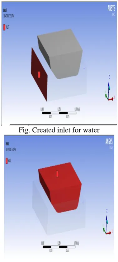
Fig. Created inlet for water
Fig. Created wall on ship hull
Fig. Assigning water properties
Fig. Assigning water inlet velocity properties
Fig. Pressure streamline results on ship hull
Fig. Velocity streamline results on ship hull
STRUCTURAL ANALYSIS OF SHIP HULL 85 mm BLOCK COEFFICIENT
Cb =
Displaced volume of hull
= 700*85*2*sin(145) = 68255.5959 mm2 Volume of water boundary
Fig. Imported model in ansys cfd
Fig. Created mesh on ship hull
Fig. Created inlet for water
Fig. Created wall on ship hull
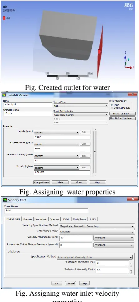
Fig. Created outlet for water
Fig. Assigning water properties
Fig. Assigning water inlet velocity properties
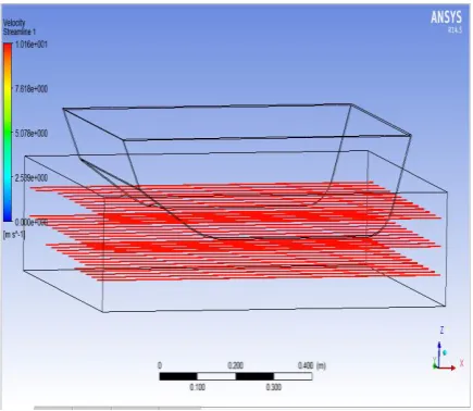
Fig. Velocity streamline results on ship hull
RESULTS AND CONCLUSION
In this project, Fluid pressure founded on different ship hulls at flow condition in water . Results are tabulated below
Results 75mm Ship Hull
85mm Ship Hull
Block coefficient
0.005 0.0061
Pressure (Pa) 1901 1742 Velocity (m/s) 10.17 10.16
Comparing all results 85mm block depth ship hull produced high block coefficient at low fluid (water stream) pressure and velocity.
References
[1]“Vibration analysis and Structural system” by Prof. M. Mukhopadhyay Dept. of OENA IIT Kharagpur.
[2]“Hydro elasticity of ships” by R E D Bishop and W G Price.
[3]“Development unit note no. 30 examples of ship vibration analysis” by Lloyd‟s Register of shipping.
[4]PRO-E & ANSYS 15.0 Manuals.
[5]Vorus, William S., Principles of Naval Architecture, Chapter 7 “ vibration”, Published by, The Society of Naval Architects and Marine Engineers, 1988. [6]Vibration Control in Ships, Published by
Veritec, Hovik Norway, 1985.
[7]IACS - Common Structural rules for Bulk Carriers 2006.
[8]Ultimate Limit State Design of Ships Hulls, By J. K. Paik, Ge. Wang, B. J. Kim, A. K. Thayamballi.
[9]Guidance for Ultimate Hull Girder Strength Assessment, By Korean Register of Shipping Sept. 2003.