SUN 3 MBit Ethernet Board
Features
• Implements Xerox 3 MBit/sec Ethernet Specifications
• Performs Ethernet Data Link Layer Functions
data encapsulation, framing, addressing, CRC generation/checking.
CSMA/CO data link management and contention resolution • Performs Ethernet Physical Layer Functions
data encoding and decoding channel access
• High Station Performance back-to-back packet capability full-duplex operation
4K byte packet buffers for receiver and transmitter
bit-vector address recognition allowing any multicast groups
4 MByte/sec bus transfer rate O-access time device
• Exception Reporting and Diagnostics
timeout on transmit
error status on receive loopback capability
• single board compatible with IEEE- 796 Bus (Intel Multibus) 6.75 by 12 inch board
796-compatibility: 016116 VOL 16-bit parallel port host interface
readily compatible with most micro and minicomputers
• 5V·only operation
onboard 15V voltage converter for transceiver
Overview
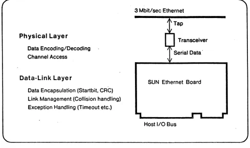
The SUN 3 MBiVsec Ethernet board provides a high-performance interface between the "experimental" 3-MBit/sec Xerox Ethernet and the IEEE-796 Bus (Intel Multibus). It supports a full implementation of the 3 MBiVsec Ethernet data link layer and physical layer in hardware/firmware.
On-board packet buffering avoids real-time demands on host computer system. Parallel port type host interface is compatible with most micro or minicomputers and has data transfer throughput up to
SUN Ethernet Board Architecture
The SUN Ethernet board was designed
as a
high-performance 3 MBitlsec Ethernet interface capable of supporting workstations, gateways, TIPs, and other busy servers. The board performs all specified data link layer and physical layer functions and provides packet buffering. As shown in Figure 1, the SUN Ethernet board in conjunction with a transceiver unit provides a microprocessor host system with a complete connection to the 3 MBiVsec Ethernet local area network.Physical Layer
Data Encoding/Decoding Channel Access
Data-Link Layer
Data Encapsulation (Startbit, CRC) Link Management (Collision handling) Exception Handling (Timeout etc.)
•
3 Mbitlsec Ethernet
Transceiver
SUN Ethernet Board
Host I/O Bus
Figure 1: The SUN Ethernet Interface
Figure 2 shows a 3 Mbitlsec Ethernet packet. The packet contains a single startbit, followed by eight bit fields for destination address and source address, a variable-length data field, and a 16-bit CRCcode.
r
Destination Source""'"
StartBil Address Addre •• DATA CRC
' - 1-Bit B-Bit B-Bit 16 TO 2048 Bytes 16 Bit
./
Figure 2: A 3 MBitlsec Ethernet Packet
to an Ethernet has a "native" address to identify it. Since this address is relative to a particular Ethernet, the native address is usual1y switch selectable.
The data field allows arbitrary information of variable length to be transmitted. Although the original Xerox 3 MBitlsec Ethernet does not specify size constraints for the data field, it is recommended that the minimum data field is 816·bit words or 16 Bytes and the maximum is 102416· bit words or 2048 bytes. The rational for the minimum length is to avoid "invisible" collisions. The maximum packet length assures that no single station can monopolize the network.
r+
RX,
......
,
li\ J\
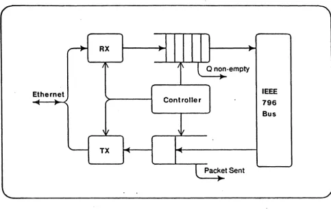
Q non·empty
..
,
Ethernet IEEE
~
..
Controller796
...
,
Bus
,It ,It
-
TX ... ...L
Packet Sent...
-,
Figure 3: SUN Ethernet Block Diagram
SUN Ethernet Board Functions
The SUN Ethernet board performs all the Data Link Layer and Physical Layer functions for the
3
Mbitlsec Ethernet. These functions include transmit data encapsulation, transmit data encoding. transmit link management, receive data decoding. receive data decapsulation, and receive link management. The functions are implemented in such a way to allow maximum station performance and to provide a simple host computer interface.
Transmit Data Encapsulation and Encoding
The packet to be sent. including address and data fields. is prepared by the .host computer and loaded into the on·board packet buffer. During transmission, the SUN Ethernet interface generates the st~rtbit preamble for all receivers on the network to synchronize on. converts the packet from word·parallel to bit·serial. computes the 16·bit CRC value and appends it at the end of the packet. The serial bit· stream to the Ethernet transceiver is Manchester·encoded to be self·synchronizing.
Transmit Link Management
The SUN Ethernet board incorporates all functions necessary to sucessfully deliver a packet onto the network. These functions include:
Carrier Deference: The SUN Ethernet interface defers any transmission until the cha~nel is idle and there are no other ongoing transmissions.
Collision Detection: After starting with its own transmission, a collision may occur with other Stations simultaneously starting their transmissions. Upon detecting a collision, the SUN Ethernet interface will abort its own transmission and jam the channel to enforce collision consensus.
Randomized Retransmission: When a transmission has been aborted due to a collision. the SUN Ethernet interface attempts its transmission again after waiting a randomized time period. which is computed according to a binary exponential backoff algorithm.
The SUN Ethernet interface automatically performs the exponential backoff retransmission algorithm using a slot time of 42 microseconds. The mean value of the retransmission time interval is thus MIN (number of retries, 8) • 42 microseconds)/2. When retransmission attempts have been unsuccessful for more than 160 milliseconds. a timeout aborts the retransmission attempts. The interface has no preset upper limit on the number of retry attempts, except for the timeout interval. Thus the minimum number of retry attempts is 16 and the expected number of retry attempts is 32.
Rece.ive Data Decoding and Decapsulation
Manchester·encoded data from the Ethernet is decoded on the SUN Ethernet interface with a , digital phase·locked loop and then converted from bit·serial into word·parallel.
The SUN Ethernet interface removes the startbit from the packet and checks the destination address of all incoming packets against an address filter, only accepting packets with matching addresses. An accepted packet is placed into the receiver FIFO buffer together with its status.
The SUN Ethernet interface validates the integrity of a received packet by generating a CRC on the received bit stream and checking it against the CRC found in the packet, by checking that the packet consists of an integral number of words and that no phase distortion or collision was associated with reception of the packet.
Receive Link Management
Collision detection and carrier deference cause most collisions on the Ethernet to result in fragemented packets only a few bits long. The SUN Ethernet board rejects packets fragments that are shorter than 17 bit times or 5 microseconds. Longer packets that pass through the address filter and collide at a later point appear in the receiver FIFO with error status.
IEEE· 796 Bus Interface
The host processor bus interface is a 16·bit parallel port compatible with the IEEE-796 Microcomputer Bus standard (Intel Multibus). This interface is also compatible with virtually any host computer that offer parallel port interfaces.
The host computer communicates with the Ethernet interface through three read registers, three write registers, and an interrupt line. The registers are accessible as 4 consecutive word addresses that can be located on a 256-byte boundary anywhere in the 16-bit 796-Bus I/O address space.
High Station Performance
The SUN Ethernet board has been designed to offer maximum network performance and maximum data-bus through-put while minimizing the service load placed on the host computer.
The SUN Ethernet interface includes a 4K Bytes receiver FIFO that buffers the host computer
system from the unpredictable arrival times of network traffic. A 4K Byte buffer size offers a latency of 5 milliseconds, assuming 2048 byte maximum packets.
The SUN Ethernet interface can handle any number of back·to-back packets (multiple packets immediately following each other) and allows full-duplex transmission and reception. Thus it can receive packets sent to itself (Ioopback packets), allowing self-testing.
Comparision between 3 and 10 MBit/sec Ethernets
The 3 MbiVsec Ethernet is the "original" Ethernet developed at Xerox Corporation from which the "standard" 10 MBiVsec DEC/Intel/Xerox Ethernet evolved.
3
MBiVsec Ethernets are in use inside Xerox Corporation and at several Universities and research institutions, including Stanford University, MIT, Cal·Tech, Rochester, and Carnegie· Mellon. The SUN Ethernet board addresses primarily the market of existing3
MBiVsec network installatios and applications for which the3
MBiVsec specifications are advantageous. It is also suitable for implementing gateways between 3 MBiVsec and 10 MBiVsec Ethernets.The main differences between 3 and 10 MBiVsec Ethernet are in packet format, timing, and transceiver signal levels. .
Packet format: A 3 MBit/sec Ethernet packet has a single start bit, 8-bit destination and source addresses, an integral number of 16·bit data words, and a 16·bit CRC code. A standard 10 MBiVsec Ethernet frame uses a 64·bit preample, 48·bit addressing, and a 32·bit CRC code. The minimum recommended packet length for 3 MBit/sec is 20 bytes, for 10 MBit/sec the minimum is 72 bytes. Maximum recommended packet length for 3 MBit/sec is 2052 bytes, for 10 MbiVsec the maximum is 1526 bytes.
Timing: Besides the obvious difference is the bit rate, the two networks differ in interpacket spacing time and slot time. The 3 MBit/sec Ethernet places no restrictions on interpacket spacing, whereas at 10 MBit the interframe spacing is 9.6 microseconds. 3 MBit/sec slot time has varied from 28 to 42 microseconds, on 10 MBit/sec the slot time is specified as 50 microseconds.
Transceiver: 3 MBit/sec Ethernet uses a "TTL" transceiver wi~h unipolar drive, wheras the 10 MBit/sec Ethernet uses an "ECl" transceiver with bipolar drive. It is possible to adapt the SUN Ethernet board to standard 1 0 MBit/sec Eel transceivers that can operate at a 3 MBit/sec frequency. In this case, it appears that 3 MBit/sec Ethernets can be intermixed with 10 MBit/sec networks on the same coaxial cable. It is also possible to embed maximum·size 10 MBit/sec frames in 3 MBiVsec packets.
References
R.M.Metcalfe and D.R.Boggs, "Ethernet: Distributed Packet Switching for local Computer Networks", Communications of the ACM, 19, 7, July 1976.
Using the SUN Ethernet Interface
Sending a Packet
After preparing the packet to be sent, including addresses but excluding CRC, the host ct)mputer loads the packet into the on-board transmit packet buffer. To load a packet, the host first writes a control word specifying the total number of words in the packet (the wordcount) and then the specified number of data words to the TRANSMITTER OATA PORT. Upon completing this transfer, the
Ethernet interface automatically attempts to acquire the Ethernet and to send the message.
The Ethernet interface returns to the host with a TRANSMITTER interrupt either when the message has been successfully sent or when the timeout interval of 160 milliseconds has expired without having sent the message successfully. The TIMEOUT bit in the READ STATUS register is set when the message was not sent successfully.
Receiving Packets
When a incoming packet passed the address filter and has been completely received, it is put into the receiver FI FO buffer, prefixed with a control word that specifies its length (word count) and its status. The packet status indicates whether there was a CRC-Error, a collision, or a FIFO overflow
associated with the packet. Another status bit, the QEMPTY bit, is set whenever the FIFO is empty and is cleared when a complete packet is waiting in the receiver queue. Repeated read attempts beyond a
QEMPTY control word will always return the same control word, thus the receiver FIFO cannot
underflow.
When the FIFO is non-empty, the RECEIVER interrupt is set to inform the host that a valid control
word can be read from the interface. In response, the host computer will read the control word and the specified number of words from the RECEIVER DATA PORT. Packets with error status can be analysed to collect network diagnostics or they can be simply discarded. In any case, all packets must be removed from the receiver queue by reading the specified number of words.
A slight complication is caused the fact that the RECEIVER DATA PORT is a look-ahead port. This implies that the first word read after a RECEIVER interrupt is invalid and needs to discarded. The second word read contains the actual status and the wordcount of the packet. Only the first packet read after the queue was previously empty is an invalid lookahead word, the lookahead is transparent for any other packet waiting.
Interrupt Handling
, The SUN Ethernet interface uses a single interrupt line to signal transmitter or receiver interrupts to the host· computer. Transmitter and receiver interrupts can be separately enabled by setting the corresponding bits in the WRITE STATUS register. The interrupt level can be selected under software control via the INTERRUPT LEVEL bits in the WRITE STATUS register.
Upon receiving an interrupt, the source can be distinguished by reading the READ STATUS register. A transmit interrupt can be cleared in software by accessing the CLEAR TX INTERRUPT location. A receiver interrupt is cleared automatically whenever the receiver FIFO is empty.
The maximum latency to deal with RECEIVER interrupts is 5 milliseconds, which is the shortest time in which the receiver buffer could fill up assuming a maximum packet length of 2048 bytes.
Initialization
Before the Ethernet interface can be used, it must be initialized from the local host computer. This involves loading a valid address map into the receiver, enabling of the transmitter and the receiver, and enabling interrupts.
Initializing is done via the WRITE STATUS REGISTER. Upon hardware reset, all bits in the WRITE STATUS REGISTER are set to ones. Thus INIT and LOOPBACK are asserted (enabled) whereas RECEIVER
and TRANSMITTER INTERRUPT ENABLE is negated, disabling interrupts to the host computer. The INIT
flag has two effects: First, it disables the Ethernet receiver and enables loading of the address filter. Second it causes the controller to initialize the buffer pointers. The LOOPBACK bit isolates the transmitter and the receiver from the Ethernet transceiver and connectes the transmitter directly to the receiver.
The address filter is loaded address by address under host control. First, INIT must be set to enable address loading. Then for each address the desired data bit is set up in the FILTER DATA Bit in the
WRITE STATUS register and the address is written to the WRITE ADDRESS register.
The Ethernet interface also has a switch able hardware address that can be accessed as the READ ADDRESS. This is a read·only hardwired switch that does not affect the address filtering in the
receiver. Its purpose is to establish an initial Eth~rnet address after booting.
To connect to the Ethernet, the INIT and LOOPBACK bit need to be cleared. Also, for interrupt driven software, the desired interrupt level on the bus is programmed into the WRITE STATUS REGISTER and
Interface Registers
R/W
Adrs
Read
o
Read
4Read
6
Write
0
Write
4Write
6Data
(0 .• 16>
Receiver Data Port
Format for control word:
(0:11>
Word Count
<12:16>
(12)
CRC-Error
<13>
Collision/Abort
(14)
Receiver queue overflow
(15)
Qempty
Status Register
Interrupt Flag
Read
<12>
<13>
<14>
<15>
Receiver Interrupt (before enable)
Transmitter Timeout
Transmitter Interrupt (before enable)
<0 ..
7>
Read Hardwired Switch Address / Clear Tx Interrupt
<0 .. 15)
Transmitter Data Port
Format for control word:
<0:11>
Word Count
<12:15> 0
<8 ..
15)
Write Status Register
(all bits set to 1 on hardware reset)
<8 ..
10)
Interrupt Level (inverted)
<11>
Receiver Interrupt Enable (inverted)
<12>
Transmitter Interrupt Enable (inverted)
<13)
Filter Data Bit (inverted)
<14)
Loopback (non-inverted)
<16>
Init (non-inverted)
(II .Specifications
Network
-experimental· 3 MBit/sec Xerox Ethernet
8-bit addressing, 16-bit CRC, up to 2048 Bytes Data. coaxial cable up to 1 kilometer
up to 256 transceivers per cable
Transceiver
Compatible with Xerox TTL transceiver, Part # 209926.
Mating Connector: 26-pin flat cable.
Transceiver Signals: TxData\, RxData\, Collision, +5V, +15V
Functions
Implements 3 MBit/sec Data link layer Functions
4K Byte FFO buffer for receiver
4K Byte Buffer for transmitter handles back-to-back packets loopback capability for self-test bit-vector address filtering local address switches
796-Bus Compatibility
,
016 116 VOL, 16-bit data only.
Electrical Characteristics
vce •
+5V +-5X, ICC • SA max.15V Voltage Converter for Xerox transceiver included on board.
Physical Characteristics
Width: 12.00 in. (30.48 cm) Height: 6.75 in. (17.15 cm)
Depth: 0.50 in. (1.27 em)
Weight: 16 oz. (447 g)
Envi ronmental Cha racte ristics
General Description
Installation Manual
-SUN Microsystems Inc. May 1982
The SUN 3 MBit/sec Ethernet Board provides the connection of the SUN Workstation and other machines using the Intel Multibus (TM) backplane to Ethernet-l, the experimental 3 MBitlsec Ethernet developed by Xerox PARCo
The SUN 3 MBitlsec Ethernet Board interfaces with the CPU via programmed I/O and interrupt. In Multibus notation, the board is a I/O slave with l6-bit addressing and l6-bit data paths. Note that the board is not readily compatible with 8-bit Multibus I/O.
Unpacking Instructions
Inspect the shipping carton immediately upon receipt for evidence of damage. If the shipping carton is severely damaged, request that the carrier's agent be present when the carton is opened. If the carrier's agent is not present when the carton is opened and the contents are damaged, keep the content and carton for the agent's-inspection.
It is suggested that salvageable shipping cartons and packing material be saved for future use in the event the product must be reshipped.
Installation Conside rations
The board is designed for installation into a Intel Multibus compatible backplane or card cage.
POWER: The Board requires a 5V power supply and draws a maximum current of 6 Amp. The board
includes an on-board voltage converter that generates the 15V power for the Xerox transceiver.
COOLING: The board dissipates 30 Watts. When installing the board in an enclosed environment or under restricted airflow conditions, ensure that the internal operating temperature does not exceed 130 degree F or 55 degree C.
CAUTION: To prevent possible equipment damage, do not install board in a card cage while power is
on. Also, to prevent damage due to static voltages, av~id exposing the board to plastiC materials.
Ethernet Tranceiver and Cable
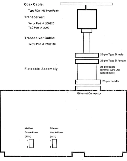
The SUN 3-Mbit Ethernet Board is designed to interface directly to the Xerox 3-Mbit Transceiver part # 209926. This transceiver is also available as TLC Part # 2000. The cables described below apply to this particular transceiver. The assembly is shown in Figure 1.
conductor and a chara~t~ristic impedance of 75 Ohm. The Ethernet cable must be terminated at both ends with a 75 Ohm terminator.
Cable between Transceiver and Board
The cable that connects the transceiver to computing equipment is Xerox Part
.
# 216411 D. The cable contains six twisted pairs of wire and features a female 15'pin D-connector on the transceiver side and a male 25-pin D-connector on the receiver side. The cable can be up to 15 meter long.The SUN Ethernet board is designed to interface directly to the above Transceiver cable via a flat-cable assembly. The flat flat-cable consists of a 26-pin header and a 25-pin D-type female connector, with wire-l connecting to pin-l of both sides and wire-26 ommitted for the 25-pin connector. It is recommended that the flat cable not exceeds 1 meter in length.
Switches on SUN Ethernet Board
The SUN Ethernet Board has two octal dip-switches: one to select the Multibus base address and one to select the local Ethernet host address. The location of these switches is shown in Figure 1.
Switch Setting for Multibus Base Address
The SUN 3 Mbitlsec Ethernet interface communicates with the host CPU via 4 read and 4 write registers located in Multibus I/O space. The registers are located on successive word (16-bit) boundaries starting on a 256-byte boundary within the 64k Multibus I/O space. Only the eight high-order address bits are decoded for the selection of the board; thus the interface will respond to 256 consecutive byte addresses even if only 4 word addresses are decoded.
To select the Multibus base address, take adqress bits AB .. A 15 of the desired address and encode them into dip-switch S505. Switch # 1 is the least significant bit, and "1" bits correspond to "ON" switches.
By convention, Oxl00 is the normal address for the first Ethernet board, and subsequent boards if any are placed at successively higher addresses.
Switch Setting for Ethernet Host Address
After obtaining an Ethernet host number from your local Ethernet administrator, express it in binary and set it into dip-switch S507. Switch # 1 is the least significant bit, and "0" bits correspond to "ON" switches, unlike the correspondance used for the Multibus base address.
Type RG11/U Type Foam
Transceiver:
Xerox Part # 209926 TLC Part # 2000
Transceiver Cable:
Xerox Part # 2164110
Flatcable Assembly
Multibus Ethernet
Base Address Host Address
(8505) (5507)
:0
:0
I
I
11
J
25-pin Typ eO male11
1
25-pin Type 0 femaler...,.----....,. ...
26-pin cable (ommitt wire 26) (3 feet max.)
11
I
26-pin header'---_-.11
1
Ethernet Connector
~
n
~ z
n
'" .., ,.
'" .... JJ Z m -I Z -I m
5
~I ~
~ » ;; (")~ m
~I
JJ;;: m
~ (")
::.! m
l::; m
~I < ;; JJ
~ n ~
~
'"..
... o
~ m m -I :J: G> "T\ en r-~ ~ ~ c... I» ::J co
.,..
o U) (,) (,) ... ~C» !;l
Rl.PU
RX.IIOAD PO.SHIFT
PO.DATA
RX.PU U.CRCERR
PO.OATA
11
1 OOOOSR
I: 01
14
~~ 1452986 04 UZII
' : 06 18 De
01SL 0:60SICItRGIGZ
PO.SHI
ATLTI
R.AIORT
R.CKERR
RX. Fcn
--\ RX.AO
.,
. X. R. FDIN11411
Z AD ~E CE
AI AZ :: 83dm AS A8 AI
I! A8 A9 OINOOU
"D
Rl.FDDUTOO~ZO
3 01 01
OZ 02 6 03 03
0404
06 06
1406061
0101 8 08 08 CLKOf
R.READ\
~
~
~ ......
z" ~
c
<= z <
" ~ ~ .... ~ ~ ....
I
,.., S " z,. ~ 0 ~ :D z m --I Z --I m :D "'11 » (') m --I :D » z en 3l: --I --I m :D m
1\) r
m --I :x: G> "'11 en ~ <-c: ;:, IX) ~ en t.l 0 1\) ~I ;;: .., ,. ~ en~ DO 3 08 01 01 DI T .WRITEI H. LOAD ~ n.GO\ tli.42-0 H.PU
fl5ffi,
- - r i l l! 01 01 oviIIOSR
02 02 60VI e 03 03 DY2
14LS299 04 04 DV3 U2t4 06 06 1 1 DYC DB 08 1 DV6
~~ ~~ 1 I DYB DY~L OEOS1CltR GIG2
~
l:lJrrnt
3 IJ3I3 2 7 Dv;!lOSR 01 01 6
1 02 0' e DVI
e 03 03 1 on 74L5299 13 04 04 2 DVJ U3t4
16 g~:
140506 1 Ii 06 Qf5 1
1 g~ g~ 19 1 Dye DV~L 0~OSICItRGIG2
~
TX.pupnlTJsI1
3 TX. LI
340. - 70
I_H~ROA'
:..!!!!!.2!:!I
X,J(MTOATAl Z .ReVDATA:
. LlISIo~e
• - 1
, . ' __ 0_ 6
;340.1 0-0 )
GNO
H .CRCOUT
~ x. la. GND PO.CARRIER x. C340.170-0
. TX.PU
~ 1A11Y 18 lC. KMTDAU\
1A2lY
14 •• .VDArA'
IA31V 1111. COL ON' IA41V GNO x. X.XIITDATAt ~ A1ZY
AZ2Y
-Any
ca<' • - 10
A42V x.
IG2G
l'ili LOOPBACKI
4LSU
u316~e ~ li.tRell ~U:O; ~ lX.DATA
TX . JAM TX. JAMI
H.GO
x.
n.CReI. II 9401
I;,'~O.O-I!L I P U6~ IZ TX.eReOUT
TX.STATEO 10 eWE • \3
TA.IDL 411R
P
~
n
,~ ~
n
z
~
rn :c
~. »
~I 'TI ;; ()
~ rn
i
~ ()
1: 0
:: z
:< ~
~ :c
;: 0 ::; r-~
~
n
~ ~
;: .,
.
... <>~
rn
w
rn
~
:r
Cj)
"
en
0
.,. =
~
c:
:J CD
....
m w
0
w:: =:
'" n ~ z n ~
;
5
'" ... ~ z 0 ~ 0 ~E
... -<'" ....
i
0n
~ ~
~
G
.
w a ... :0 Z m -l z -l m :0 "TI » (') m 0 » -l » -0 » -l :::c C/Jm ;::
.,.. r
m -l :::c G> "TI C/J
.,..
~I c...c:
:::J
co
.,..
(J)
.,..
(J).,..
: lI: (J)!i:01 04
5JlL
o3DZDloO9121
o3DZDIDOC.IO I 10 I 10
II II
I IZ IZ
13 13
14 14
II It
It II
6 17 17
18 II
C.AO AO
AO
AI AI
.AZ
I AZ AZ
.A: A3 A3
C.80 leo AMZ801 I 80 ANnOI .s: I II UIOZ ~BI UI03
+'82
Z B3 21 BZB3 CI70."-0 I
I
SO Y 3
oo~r
COZ~
tUliep 03 53 G p C4 OO~ sol!-CO~ C.NEG °lfnzYlYoITl1
f!
VRI F3 I FO
°lfnzYlYo
IT~
DO
lIT
91~z
o30ZOlo0I 10 I II I IZ
13 14 II 18 17 It
4 AO AI AZ A3 I so I Sl
BZ 83 03 8 53
~
I CP 32 G PU
3 VR
31 F3 II FO
ANnOI UIO.
001Z!
nil
SO 9 •
colZ9 c..18
°1f3Y2Y1YO
~O 3~Z
0101
2 02 03 Q3 ~2
g:
g:
I14 g~ g~
08 08 CLKOE
~8
3;'~¥h
Z0101 OZ OZ I 03 03 13 0404 1
0606 I
L 11 08061 18 g~ 3~ I CLKOE C170.81-0
JJ
DO
AO 1011 AO • AO AI AI
AZ AZ
Al A3
AC 3 A4 AI AI AI AI A7 3 A7 AI AI A8 A9 AIO AID
DB Z6lh Z8110
DO 91 00 9 00 01 01 OZ OZ 03 4 03 04 04 01 01
~08 08 \ 21 07 07 WE VE
CE DE CE DE
AD
26181 20lfo 01·
r
I: 00 II 01 I 01 I 02 02 I 03 03 I 04 I 04 I 06 01 I 01 7 01 07 I 07 WE VECE DE CE DE
,
IADur.,"~'
!!!f:.!!L.
'"
on ]J
n Z
m
~ rn ...
~
s
z. 3
... rn]J
on "T1
...
: l>
2 (')
'" rn
~
~
...]J
~ l>
Z
on en
... 3::
~ '" ...
i!!l ... ,... rn
~ ]J
~
:
;:co
..
..
- l O R D lrryffi o Z 1.00\ 01
0102 0303
OIIl!1 04 04
05 06 De 06 0707
-
0808ENOE C.PU
1.00\
3~
Z RX.AO 01 I02 02 03 03 0404 OS 05 De oe 0707
US O!
AORS.W£\ ~ R. FWE\
00 Z AO 10 II 1.00\
AI 8\
A2 AIInal 12
. 3\ Al Ul08 83 14
A4 U
AS 86
Ae 88
A7 17
P. WRITEREO S FS R-REG S-REGFR II P. READREO\ CECPIlECR CROECPCE
DATAD.OE\
. Tz12NU
I1zfZTZJ
OATAO.WE\II
I
DB 2 AO 10 te I.OB\
AI 81
1\ IAl A3 A'l!ll~1 BZ 13 U . I \
A4 14
A6 86
1.08\ 3flbill 2 INTO 0101
• I 02 02
\ B
g! g!
9408 08 08 Of Q
0 AS 88
A7 17 807 07 0108
FS R-RE6 S-REGFR II CECPIlECR CROECPCE
Cl CR STATUS.WE\ "i1£
\ I'
P.WRITE\
TjTr
/12r~3
GNO-P.WRITEAt. INTO I~I I.INTO\
I Y
,.,
Z y 3 y y yy
y !~ Y II Y
rn ::
(1\ r;;
m
I
.!.!!!f!
... !..:.!!!l!!RUPT5! u' •• r---v\ 74S0~3 liT
X
(j) T .INTEN
"T1
en '
-IUSREAD
'" 1
2
....
~Co. 3
c:
j
00
....
7 I0) ....
CD
(1\ :: ~
TITLE
-lttttt,~t,t,t~t,'I,ttt~tt~t~~tutti
ntt~"'t"t,'I~ti~~t~t~t~t~tit,
-S
!l ~ u !; 0 0 0
~ 0:. u> 8 11:-=.::' ...
• JIC ... ... ... Ii. 0
Ie ... • . . . _
Ie • · · U U
Ie U U U
FI LE DATE PAGE OF
ETHERNET INTERFACE, TRANSMITTER E 6 [ E T HG F S ] 4 . J un· 8 4 1 6 : 38 6 6