1474
Comparative Study Of Effects Of Different
Shapes Of Pitting On Mesh Stiffness Of Spur
Gear Using MATLAB
Ashutosh Singh, Vijay Kumar Karma
Abstract: The mathematical exhibiting of the vibrant analysis of gear has become essential with increased demand for high-speed mechanism. There are many numerical methods available for finding out the spur gear mesh stiffness like FEA methods and some numerical methods. In this present paper comparative study of effects of pitting shapes on spur gear mesh, stiffness is done using MATLAB Software. The pitting shapes considered are circular, Rectangular and Elliptical. Their effects on total deformation are also considered.
Index Terms: Circular pitting defect, Elliptical pitting defect, Gear Mesh Stiffness, Hertzian contact stiffness MATLAB, Rectangular pitting defect, Spur Gear
—————————— ——————————
1.
INTRODUCTION
Automotive transmissions are designed to use in transmission power systems between the engine and the wheels with an ability to control the torque and rotational speed output. Pitting occurs when the cyclic stresses in a gear tooth cause small cracks at or below the surface of the tooth face. These cracks will propagate into pits as the gear material fractures and are removed from the tooth. The size of the pit then grows as the removed material presents further stress concentrations on the tooth face. While the parameters dictating tooth bending fatigue are limited to geometry, material and loading levels, a large number of parameters interact to define contact fatigue conditions of gears [1]. Due to high service load, harsh operating conditions or fatigue, faults may develop in gears. Gear faults are responsible for gearbox failures. Most of these come from damage to the gear teeth such as pitting, cracking, and spalling. Crack is no lubrication related failure mode while pitting is a lubrication-related failure mode [3] Contact fatigue of gears is greatly influenced by tooth geometry as well as surface finish and lubrication parameters. These variables combined with gear material, operating speed, and temperature define the conditions for cracks to nucleate and grow into sizable pits. In this study, pits shapes effect on mesh stiffness is studied. The pit shapes considered are circular, elliptical and rectangular [4]. According to the American Society for Metals, "pitting occurs when fatigue crack is initiated on the tooth surface or just below the surface". Pits are the surface crack caused by metal to metal contact of severities due to low lubricant film thickness. High-speed gears with a smooth surface and good film thickness may experience pitting due to subsurface cracks [5]. Fakher Chaari et al [3] presented the analytical modeling of tooth cracks and quantification of the gear mesh stiffness reduction due to the tooth crack. The validation of analytical formulation is done with the finite element model. Pitting growth is shown in figure 1. Ten et al [4] –
Experimentally measured pitting growth under different levels of load. To create surface pitting in a relatively short time frame, lubricant oil without anti-wear properties was employed. Prolonged operation time resulted in pitting spreading to other gear teeth. The pitted area progression from 6.3% to 41.7% of the gear tooth surface under the test condition. Chaari et al.[3] analytically studied the effect of a single pit on the time-varying mesh stiffness of gears. The pit was modeled as a rectangular shape as shown in Figure 4. Xihui Liang et al [9] Pitting occurs when fatigue cracks are initiated on the tooth surface or just below the surface. Pits are the result of surface cracks caused by metal-to-metal contact of asperities or defects due to low lubricant film thickness. Ashish Agrawal et al [10] – analyze spur gear mesh stiffness by the mathematical and numerical method using MATLAB and MS Excel spreadsheets. Rincon et al. [11] evaluated the pitting effect on the time-varying mesh stiffness of gears using the finite element method. A single pit was modeled in an elliptical shape as shown in Figure 5. They developed a model to study and predicted the mesh stiffness from the model including the bending stiffness, axial stiffness and shear stress mesh stiffness of gears in the mesh using the MATLAB software package based on the numerical method.
2.Mesh stiffness calculation for gears having different shapes of pitting
In this study, tooth pits are modeled in a circular shape, rectangular shape and elliptical shape as did in [5]. The MATLAB software is used to find the mesh stiffness of spur gear. In this case, it is assumed to be without friction, manufacturing error and gear body is treated as rigid [7]. Our objective is to compare the effect on the mesh stiffness of different shapes of pits (Circular, Elliptical, and Rectangular) as a function of the gear rotation angle. For single tooth pair, gear and pinion teeth are considered in series combination. The single tooth contact pair mesh stiffness in a different shapes (circular, rectangular and elliptical) pitting are written below [3,5,6]
Where, Ktc, Ktr, and Kte are total mesh stiffness of the circular shape, rectangular shape and elliptical shape of pitting respectably and kb1, ka1, and ks1 are the series combination of bending stiffness, axial stiffness and shear stiffness of pinion respectably and kb2, ka2 and ks2 are the series combination of bending stiffness, axial stiffness and shear stiffness of gear respectably and kh is the Hertzian contact stiffness. [3,5,6]
Table 1. The gear parameters used in this study [3,5,6]
Parameter Values
Force(N) 7719.298
Pressure angle(degree) 20
No. of teeth in Gear 19
No. of teeth in Pinion 19
Torque in Gear (Nm) 220
Torque in Pinion (Nm) 220
Module (mm) 3.2
RPM Gear 745
RPM pinion 745
Tooth width (mm) 38.1
Contact ratio 1.21
Pitch circle radius of gear (mm)
30.4
Pitch circle radius of a pinion (mm)
30.4
Base circle radius gear (mm) 28.3
Base circle radius pinion (mm)
28.3
Root circle radius gear (mm) 26.2
Root circle radius pinion (mm) 26.2
Addendum radius gear (mm) 33.6
Addendum radius pinion (mm) 33.6
Modulus of elasticity E (Pa) 2.068*e11
Poisson‘s ratio 0.3
2.1 Mesh stiffness calculation for Circular Pitting [3, 4]
The series combination of bending stiffness (Kb), axial stiffness (Ka), shear stiffness (Ks) and Hertzian contact stiffness as calculated by [3] is given as
Figure 2. Elastic force on a gear tooth with a pit.[3]
] sin cos
)
[(12 1 1
Rb h
] sin cos
)
[( 2
1476 3
1 1
2
1 )cos sin ] cos
[( r
b R
R
d
3 1
2)cos sin ] cos
[( r
b R
R
x
L h Ax 2 x
L h L h
Ix x 3 x3
3 2 ) 2 ( 12 1
Where, Rb, Rr and L represent the base circle radius, root circle radius and tooth width of the gear respectively h is the distance between the gear contact point and the tooth central line,d is the distance between the gear contact point and the gear root, x is the distance to tooth root, Ax and Ix indicate the area
and the area moment of inertia of the tooth section, respectively. α2 is the half tooth angle on the base circle, α3 is the describes the approximated half tooth angle on the root circle and α is the angular displacement. α2 and α3 are written as:
3 arcsin( sin 2)
r b
R
R
Where Z1 and Z2 are the numbers of teeth of the gear and pinion and ∝0 is the pressure angle.
The expression of ∝1 is written as:
2 1 0 0 2 0 2 1 tan 2 ) 2 cos tan(arccos Z Z Z Z Z
For the gear tooth with pitting, the expressions of h, hx, Ix, and Ax are different from the ones given above for a perfect gear tooth. The tooth contact width is not
constant L. are used to represent the reduction of tooth contact width, area and area moment of inertia of the tooth respectively.
Where the distance contact point is x. the expression of
and are given below [4]
{ √ 2 ( ) 2 { ( )
{ 3 ( )
2
Figure 3. A tooth of gear with a single pit [4].
Mesh stiffness derivation for gear with single tooth pit:
Chen, Y.et al [4 ]derived mesh stiffness equations for gears with a single circular tooth. The circular pits do not overlap with each other and all the circles are within tooth surface area, the Bending stiffness, shear stiffness, and axial stiffness can be obtained through equations (16), (17) and (18), respectively[6].
1 *1
+ 1
2
∫
3 1(2 3
)
1 1 2 1
∫
1 2 1( 0
)
1 a 2
∫
(2 )For a pair of gear with tooth pitting, the tooth contact width is (L - ) rather than L. correspondingly, the Hertzian contact stiffness for gear pairs with a circular tooth pit can be expressed as:
Where E, L, denotes young modulus, tooth width, and Poisson's ratio respectively.
2.2 Mesh stiffness calculation for rectangular pitting [5]:
Figure 4. Rectangular pit and elastic force on a gear tooth with a pit [5]
1
∫
1 2 2 𝑖 2 2 𝑖 1∫
1 2 2 2 𝑖 1 𝑖 2∫
2 𝑖 12 ( 𝑖 2 ) 2
1
∫
0 1 22 𝑖 11
∫
1 2 3(1 1( 2 𝑖 ))2 𝑖 2 2∫
1 2 3 1 1 2 𝑖 2 𝑖 2 2∫
3 (1 1( 2 𝑖 )) 2 2 ( 𝑖 2 )2
1
∫
0 1 23 1 1 1 2 1 2 2.3 Mesh stiffness calculation for elliptical pitting [6,7]: -
Figure 5. Elliptical pit.[6]
Analytical Calculation for finding Deflection due to bending [6]:
𝑏 𝐹 𝑐 2𝛼 ∑ 𝑖{
𝑖 𝑖 𝑖 3 2𝑖
𝐸′ ̅
𝑖 𝐺 ̅𝑖
𝑖=1
2𝛼 𝑚
̅𝑖𝐸′ }
Bending stiffness of the tooth can be given by
𝑘𝑏 𝐹 𝑏
Other parameters like modulus of elasticity, a moment of inertia, and area can be given as
𝐸𝐼 𝐸 𝑣
𝑣 𝑣
̅𝑖
𝑖 𝑖 1
Analytical Calculation for finding Deflection due to bending [6]:
𝑓
𝐹𝑐 2𝛼 𝑚
𝑊𝐸 { (
𝑓2 2
𝑓) 𝑀 ( 𝑓
𝑓) 𝑃 𝑄 𝑔 𝛼𝑚 }
The coefficient , 𝑀 𝑃 𝑄 can be calculated by polynomial functions
𝑋𝑖( 𝑓𝑖 𝜃𝑓) 𝑖
𝜃2𝑓 𝐵𝑖 2𝑓𝑖
𝐶𝑖 𝑓𝑖
𝜃𝑓
𝐷𝑖
𝜃𝑓 𝐸𝑖 𝑓𝑖 𝐹𝑖
Fillet foundation stiffness can be given as
𝑘𝑓
𝐹
𝑓
Local deformation then expressed by-
𝐹 𝑘
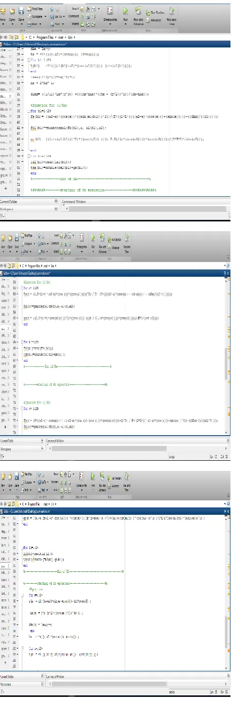
A program is created for calculating the mesh stiffness using MATLAB programming code. The input parameters for the program are pressure angle, module, addendum coefficient, number of teeth on the pinion, gear ratio, modulus of elasticity, Poisson‘s ratio and gear root diameter. By using these basic parameters, the other parameters such as base circle diameter, pitch circle diameter, addendum circle diameter, base pitch,
1 𝑘𝑠
∫
1 2 1 𝑣 𝑎2 𝑎 𝑐𝑜𝑠𝑎 𝑐𝑜𝑠𝑎1
𝐸 𝐿 𝑠𝑖𝑛𝑎 𝑎2 𝑎 𝑐𝑜𝑠𝑎
𝑑𝑎
𝑎2 𝑎1
∫
𝑎1𝑎2 1 2 𝐿 1 𝑣 𝑎2 𝑎 𝑐𝑜𝑠𝑎 𝑐𝑜𝑠𝑎1𝐸 𝐿 𝑠𝑖𝑛𝑎 𝑎2 𝑎 𝑐𝑜𝑠𝑎𝑑𝑎
∫
1 2 𝐿 1 𝑣 𝑎2 𝑎 𝑐𝑜𝑠𝑎 𝑐𝑜𝑠𝑎1𝐸 𝐿 𝑠𝑖𝑛𝑎 𝑎2 𝑎 𝑐𝑜𝑠𝑎 𝑅 𝑡
𝑑𝑎
𝑎2𝑎1
∫
1 2 1 𝑣 𝑐𝑜𝑠𝑎1𝐸 𝐿 𝑥
𝑑𝑥
𝑥1 𝑥2
0
(20)
(21)
(22)
(23)
(24)
(25)
(26)
(27)
(28)
(29)
1478 contact ratio, etc. are calculated. The mesh stiffness is
calculated to know the meshing of spur gears during transmission processes. The locations and sizes of the contact zone are calculated using the contact ratio and base pitch. A large number of points are imagined along the total contact zone for one mesh cycle. These points are taken to know spur gear mesh stiffness behavior along the complete mesh cycle. The pinion roll angle is used as a quantity for selecting these points for which mesh stiffness is to be calculated. The formulas for the first three stiffnesses for circular pitting [Eq. (16) – Eq. (18)], for rectangular pitting, [Eq. (20) – Eq. (22) and for elliptical pitting [Eq. (23) – Eq. (30)] depend on tooth geometry. These values are used to solve the mesh stiffness in the MATLAB command window and find out the equivalent mesh stiffness of different shapes of pitting [Eq. (1), Eq. (2) and Eq. (3)]. The Hertzian contact stiffness is constant all shape (HG, CPG, RPG, and EPG) of pitting for gear pairs with a written as Eq. (19).
Finally, the three stiffness‘s are calculated by using Eq.1, Eq.2and Eq. 3 and these stiffnesses are as follows:
Equivalent mesh stiffness of circular pitting
Equivalent mesh stiffness of rectangular pitting
Equivalent mesh stiffness of elliptical pitting
Figure 6 Input command window
Figure 7 MATLAB Output Screen The flow chart (as shown in Figure 4) shows the method used to calculate the total effective mesh stiffness and angular displacement.as
Figure 7 the flow chart of the method
3 Result
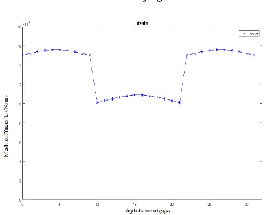
The single tooth mesh stiffness within one mesh cycle is plotted for healthy gear in figure 8 circular shape pitting in Figure 9, rectangular shape pitting in Figure 10, elliptical shape pitting in Figure 11 and comparative mesh stiffness of gear in Figure 12 represents the evolution of gear mesh stiffness along the pinion roll angle corresponding to module = 3.2mm and pressure angle = 20 deg. It has been observed that stiffness of the driving gear tooth decreases, whereas the stiffness of the driven gear tooth increases along the path of contact.
Figure 8. Mesh stiffness vs. angular displacement for healthy gear
1480 Figure 10. Mesh stiffness vs. angular displacement for
rectangular pitting gear
Figure 11.Mesh stiffness vs. angular displacement for elliptical pitting gear
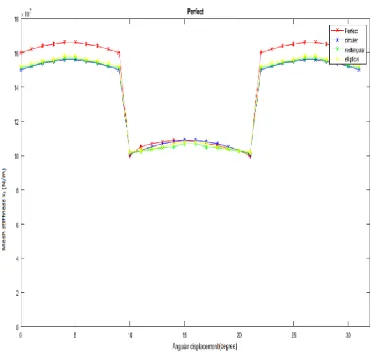
Figure 12. Comparison of healthy, circular, rectangular and elliptical pitting mesh stiffness vs. angular
displacement
4 Conclusion
The results of this study sketched and evaluated in the previous chapter and the above section allow for some useful conclusions to be made. With the gear manufacturing and finishing processes all being equal in this study, the influence on gear material has been isolated as the sole variable influencing pitting fatigue life. The following conclusions can be made - For all the considered cases in MATLAB, tooth effective mesh Stiffness of elliptical shape pitting of Spur gear is lower than the same Spur gear but the different shapes of (circular and rectangular) pitting as shown in Fig. 12(Elliptical shape pitting is 82.46%, circular shape pitting is 83.7%, rectangular shape pitting is 91.36% and healthy gear)
5 Future Work
The following recommendations can be made for future work regarding the data provided in this study.
The spur gear assembly can be collected by using the spur gear mesh stiffness as an input parameter and by using this data in the ODE Solver program in MATLAB software.
The whole procedure can be repeated for defected spur gears assembly.
References
[1]
Ueno, T., Ariura, Y., and Nakanishi, T., 1980, ―Surface Durability of Case- Carburized Gears—On a Phenomenon of ‗Gray-Staining‘ of Tooth Surface,‖ Century 2 International Power Transmissions & Gearing Conference, San Francisco, USA.[2]
The surface fatigue life of carburized and hardened M50NiL and AISI 9310 spur gears and rolling-contact test bars. (Report)Townsend, D. P., and Bamberger, E. N. NASA Tech. Memo. TM-101979 1989, 16 pp. (1990). International Journal of Fatigue,12(3), 229-229. doi:10.1016/0142-1123(90)90194-j.[3]
Chaari, F., Fakhfakh, T., & Haddar, M. (2009). Analytical modeling of spur gear tooth crack and influence on gear mesh stiffness. European Journal of Mechanics - A/Solids,28(3), 461-468. doi:10.1016/j.euromechsol.2008.07.007.[4]
Chen, Y., Jin, Y., Kang, R., Gong, W., & Yang, Y. (2017). The time-varying mesh stiffness modeling of a gear system with spalling defects in different positions. 2017 4th International Conference on Transportation Information and Safety (ICTIS). doi:10.1109/ictis.2017.8047837.[5]
Chawathe, D. D. Handbook of Gear Technology. New Age International (P) Limited, Publishers, 2011.[6]
Li, C. J., & Lee, H. (2005). Gear fatigue crack prognosis using embedded model, gear dynamic model, and fracture mechanics. Mechanical Systems and Signal Processing, 19(4), 836-846. doi:10.1016/j.ymssp.2004.06.007Time-varying mesh stiffness calculation of spur gear pair considering sliding friction and spalling defects. Engineering Failure Analysis,70, 200-211. doi:10.1016/j.engfailanal.2016.09.003.
[8]
http://www.tutorialspoint.com/matlab/matlab_overvi ew.htm.[9]
Liang, X., Zuo, M. J., Feng, Z., & Liu, L. (2016). A mesh stiffness evaluation model to reflect tooth pitting growth of a pair of external spur gears. 2016 Prognostics and System Health ManagementConference (PHM-Chengdu).
doi:10.1109/phm.2016.7819811.
[10]
Karma, Vijay, and Ashish Kumar Agarwal. ―Calculation of high contact ratio spur gear mesh stiffness and load sharing ratio using MATLAB & excel spreadsheet.‖ International Journal of Advance Research in Science and Engineering, vol. 5, no. 9, Sept. 2016.[11]
Rincon, A. F., Viadero, F., Iglesias, M., García, P., De-Juan, A., & Sancibrian, R. (2013). A model for the study of meshing stiffness in spur gear transmissions. Mechanism and MachineTheory,61, 30-58.
![Table 1. The gear parameters used in this study [3,5,6]](https://thumb-us.123doks.com/thumbv2/123dok_us/8631053.1420761/2.612.31.286.232.372/table-gear-parameters-used-study.webp)
![Figure 3. A tooth of gear with a single pit [4].](https://thumb-us.123doks.com/thumbv2/123dok_us/8631053.1420761/3.612.326.569.67.247/figure-tooth-gear-single-pit.webp)
![Figure 4. Rectangular pit and elastic force on a gear tooth with a pit [5]](https://thumb-us.123doks.com/thumbv2/123dok_us/8631053.1420761/4.612.36.275.282.642/figure-rectangular-pit-elastic-force-gear-tooth-pit.webp)