International Journal of Emerging Technology and Advanced Engineering
Website: www.ijetae.com (ISSN 2250-2459,ISO 9001:2008 Certified Journal, Volume 4, Issue 6, June 2014)
366
Design and Development of Multilevel Inverter by Using
Equal/Unequal DC Sources
Chaithra G R
1, Dr. Ashok Kusagur
21
PG student, 2Associate Professor, E&E Department, UBDT college of Engineering, Davangere, India
Abstract—Multi level converters technique emerged
recently for high voltage and power electronic applications. The computed switching angles for multilevel converter produce the required fundamental voltage and also suppress the higher order harmonics. The 7 level equal step output voltages generated from cascaded multilevel inverter from 3 equal and also 2 unequal battery sources.
Keywords—Cascaded H-bridge multilevel inverter, unequal battery sources, equal battery sources, resistive load, total harmonic distortion
I. INTRODUCTION
THE KEY ISSUE in designing an effective multilevel inverter is to ensure that lesser total harmonic distortion (THD) in the voltage output waveform. Multilevel inverters provide more than two voltage levels. A desired output voltage waveform can be synthesized from the multiple voltage levels with less distortion, at low switching frequency, higher efficiency, and lower voltage rating devices. This requires an (mathematical) algorithm to determine when the switching should be done so as not to produce harmonics and a fast real-time computing system to implement the strategy.
A method was reported in[1] and [2] that presented a procedure the switching angles for the H-bridges in a cascaded converter using the mathematical theory of resultants. In that work, a complete solution was presented for computing all possible switching angles that achieved the requisite fundamental voltage and eliminated lower order harmonics. Usually the dc sources were all equal, which will probably not be the case in applications even if the dc sources are nominally unequal.
Specifically, eliminating harmonics in a multilevel converter in which the separate dc sources do not have equal voltage levels is considered. Generally each phase of a cascaded multilevel converter requires n DC sources for 2n + 1 level. For many applications, to get many separate DC sources is difficult, and too many DC sources will require many long cables and could lead to voltage unbalance among the DC sources.
To reduce the number of DC sources required when the cascaded H-bridge multilevel converter is applied to a resistive load, a scheme is proposed in that allows the use of two unequal DC sources to generate 7 level step multilevel inverter output and 3 equal dc sources to generate 7 level step multilevel inverter output.
This scheme provides the capability to produce higher voltages (where they are needed) at low switching frequency, has inherent low switching losses and high conversion efficiency. For electric/hybrid electric vehicle motor drive applications, two H-bridges for each phase is a good tradeoff between performance and cost. For the required fundamental output voltage, it is desired to find out the switching times (angles) that produce the fundamental and no specifically defined harmonics. In this paper, the lower order harmonics are eliminated making use of two unequal DC voltages for H-bridges and also three equal DC voltages.
II. CASCADED H-BRIDGES
International Journal of Emerging Technology and Advanced Engineering
Website: www.ijetae.com (ISSN 2250-2459,ISO 9001:2008 Certified Journal, Volume 4, Issue 6, June 2014)
[image:2.612.54.281.437.673.2]367 Fig.1 Single-phase structure of a multilevel cascaded H-bridges
[image:2.612.337.553.508.685.2]inverter
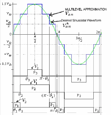
Fig. 2: Seven level equal step output voltage using unequal dc sources
The conventional method for generating 7 level multilevel inverter output waveform was done by using three batteries of equal magnitude and also three cascaded H-bridges. In this scheme the duty cycle for each of the voltage level is different. If this pattern of duty cycle is used on a motor drive continuously, the level 1 battery is cycled on for a much longer duration than the level 3 batteries. This means that the level 1 battery will discharge much more than the Level 3 battery. This problem does not occur for the multilevel inverter with unequal dc sources switching scheme shown below. In this paper a switching scheme is proposed for multilevel inverter with unequal batteries. In which v1=output of H1=Vdc andv2= output of H2 = Vdc/2 for unequal batteries. From θ1 to θ2, voltage v2will appear at the output (i.e. Va-n) and from θ2 to θ3, voltage v1 will appear, from θ3 to θπ-θ3 voltages (v1+v2) will appear, from θπ-θ3 to θπ-θ2 voltage v1 will appear,
and from θπ-θ2 to θπ-θ1 voltage v2will appear at the output.
Hence both the batteries discharge equally in every half cycle (i.e. for every 900).
III. WORKING PRINCIPLE FOR UNEQUAL BATTERIES
To operate a seven level cascaded multilevel converter consider two unequal dc sources, the magnitude of voltage of first dc source is Vdc (i.e., the battery connected to first H-bridge, H1) and the magnitude of voltage of second dc source is Vdc/2(i.e., the battery connected to second H-bridge, H2).[5]
Consider the dc source for the first H-bridge is V1 with an output voltage of Vdc and the dc source for the second H-bridge is V2 with an output voltage of Vdc/2.
International Journal of Emerging Technology and Advanced Engineering
Website: www.ijetae.com (ISSN 2250-2459,ISO 9001:2008 Certified Journal, Volume 4, Issue 6, June 2014)
368
By giving the triggering pulses to the switches of H1 appropriately, the output voltage V1 can be made equal to +Vdc, 0, -Vdc. While the output voltage of H2 i.e., V2 can be made equal to +Vdc/2, 0, -Vdc/2
The output voltage of the converter can have the values
dc dc dc
dc dc
dc dc
v v v
v v
v v
2 ,
2 , 0 ,
2 , , (1)
These are the 7 possible output levels. Figure 2 shows the 7 level equal step output voltage waveform.
IV. WORKING PRICIPLE FOR EQUAL BATTERIES
Fig4: single phase of the proposed H-bridge inverter with equal dc sources
To operate a seven level cascaded multilevel converter consider two equal dc sources, the magnitude of voltage of first dc source is Vdc (i.e., the battery connected to first H-bridge, H1), the magnitude of voltage of second dc source is Vdc(i.e., the battery connected to second H- bridge, H2). The magnitude of voltage of third dc source is Vdc (i.e., the battery connected to third H-bridge, H3). [3]
Consider the dc source for the first H-bridge is V1 with an output voltage of Vdc, the dc source for the second H-bridge is V2 with an output voltage of Vdc and the dc source for the third H-bridge is V3 with an output voltage of Vdc.
By giving the triggering pulses to the switches of H1 appropriately, the output voltage V1 can be made equal to +Vdc, 0, -Vdc. While the output voltage of H2 i.e., V2 can be made equal to +Vdc, 0, -Vdc and the output voltage of H3 i.e., V3 can be made equal to +Vdc, 0, -Vdc.
The output voltage of the converter can have the values (Vdc), (2Vdc), (3Vdc), 0, (-Vdc), (-2Vdc),(-3Vdc) (2)
V. MATHEMATICAL MODEL OF SWITCHING FOR THE
MULTILEVEL INVERTER WITH UNEQUAL BATTERIES. The Fourier series expansion of the 7-level equal step output voltage waveform is
5 , 3 , 1
3
2 1
sin cos
cos cos
4 )
(
n
dc
t n n
n n
n v t
v
(3)
Where n is the harmonic number of the output voltage. Given a desired fundamental voltage V1, one wants to determine the switching angles θ1, θ2, θ3 so that V (ωt) = V1sin (ωt), and specific higher order harmonics of V (nωt) are eliminated. For three-phase motor drive applications, the triple harmonics in each phase need not be considered as they automatically disappear in the line-to- voltages. In this paper, the goal is to eliminate the 5th harmonic and the 7th harmonic. Mathematically, this can be formulated as the solution to the following equations.[4]
cosθ1+cosθ2+cosθ3=m cos5θ1+cos5θ2+cos5θ3=0
cos7θ1+cos7θ2+cos7θ3=0 (4) This is a system of three transcendental equations with three unknowns’ θ1, θ2 and θ3. There are many ways to solve for the switching angles. One approach to solving this set of nonlinear transcendental equations (4) is to use an iterative method such as the Newton-Raphson method. In this work, the method given in is extended to find all solutions to (4). This methodology is based on the mathematical theory of resultants of polynomials which is a systematic procedure for finding the roots of systems of polynomial equations. In this method, the set of equations is converted to a polynomial system shown below by setting x1=cosθ1, x2=cosθ2, x3=cosθ3 and using trigonometric identities.
cos5θ=5cosθ-20cos3θ+16cos5θ (5) cos7θ=-7cosθ+56cos3θ-112cos5θ+64cos7θ
(6)
To transform (4) into the equivalent conditions
1 1 2 2 3 3 01 x v x v x v x m p
International Journal of Emerging Technology and Advanced Engineering
Website: www.ijetae.com (ISSN 2250-2459,ISO 9001:2008 Certified Journal, Volume 4, Issue 6, June 2014)
369
5 20 3 16 5
03 1
5
i i i
i
i x x x
v x p (8)
3 1 7 5 37
7
56
112
64
0
i
i i i
i
i
x
x
x
x
v
x
p
(9)Where x=(x1, x2, x3) and
d c f v V m 4 (10)The modulation index is
d c f a nv v n m m 4 (11)This follows from the fact that each inverter has a dc source that is nominally equal to Vdc so that the maximum output voltage of the multilevel inverter is nVdc. Consequently, a square wave of amplitude nVdc results in the maximum fundamental output possible of Vfmax=4nVdc/π so that
n
m
v
n
v
v
v
m
dc f f f a
4
max (12)This is now a set of three polynomial equations in the three unknowns x1, x2, x3. Further, the solutions must satisfy
0≤x1<x2<x3≤1
Substituting
3 2 2 1 1 3 v x v x v m
x
(13)
Into P5, P7 to get,
73 2 2 1 1 3 3 3 2 2 1 1 3 3 2 2 1 1 3 5 2 2 2 2 2 5 1 3 1 1 1 2 1 5 16 20 5 16 20 5 16 20 5 , v x v x v m v v x v x v m v v x v x v m v x x x v x x x v x x p (14)
7 3 2 2 1 1 3 5 3 2 2 1 1 3 3 3 2 2 1 1 3 3 2 2 1 1 3 7 2 5 2 3 2 2 2 7 1 5 1 3 1 1 1 2 1 7 64 112 56 7 64 112 56 7 64 112 56 7 , v x v x v m v v x v x v m v v x v x v m v v x v x v m v x x x x v x x x x v x x p (15)VI. MATHEMATICAL MODEL OF SWITCHING FOR THE
MULTILEVEL INVERTER WITH EQUAL BATTERIES. The Fourier series expansion of the 7-level equal step output voltage waveform is
5 , 3 , 1 3 2 1 sin cos cos cos 4 ) ( n dc t n n n n n v t v
(16)Where n is the harmonic number of the output voltage. Given a desired fundamental voltage V1, one wants to determine the switching angles θ1, θ2, θ3 so that V (ωt) = V1sin (ωt), and specific higher order harmonics of V (nωt) are eliminated. For three-phase motor drive applications, the triple harmonics in each phase need not be considered as they automatically disappear in the line-to-line voltages. In this paper, the goal is to eliminate the 5th harmonic and the 7th harmonics Mathematically, this can be formulated as the solution to the following equations.[6]
cosθ1+cosθ2+cosθ3=m cos5θ1+cos5θ2+cos5θ3=0 cos7θ1+cos7θ2+cos7θ3=0
(17)
International Journal of Emerging Technology and Advanced Engineering
Website: www.ijetae.com (ISSN 2250-2459,ISO 9001:2008 Certified Journal, Volume 4, Issue 6, June 2014)
370
cos5θ=5cosθ-20cos3θ+16cos5θ (18) cos7θ=-7cosθ+56cos3θ-112cos5θ+64cos7θ (19)
To transform (2) into the equivalent conditions
1 2 3 01 x x x x m p
(20)
5 20 3 16 5
03 1
5
i i i
i x x x x p (21)
3 1 7 5 37
7
56
112
64
0
i
i i i
i
x
x
x
x
x
p
(22)Where x=(x1, x2, x3) and
d c f nv V m 4 (23)The modulation index is
d c f a v v n m m 4 (24)This follows from the fact that each inverter has a dc source that is nominally equal to Vdc so that the maximum output voltage of the multilevel inverter is nVdc. Consequently, a square wave of amplitude nVdc results in the maximum fundamental output possible of Vfmax=4nVdc/π so that
n
m
v
n
v
v
v
m
dc f f f a
4
max (25)This is now a set of three polynomial equations in the three unknowns x1, x2, x3. Further, the solutions must satisfy
0≤x1<x2<x3≤1 Substituting
1 2
3 m x x
x
(26) Into P5, P7 to get,
72 1 3 2 1 2 1 5 2 2 2 2 5 1 3 1 1 2 1 5 16 20 5 16 20 5 16 20 5 , x x m x x m x x m x x x x x x x x p (27)
72 1 5 2 1 3 2 1 2 1 7 2 5 2 3 2 2 7 1 5 1 3 1 1 2 1 7 64 112 56 7 64 112 56 7 64 112 56 7 , x x m x x m x x m x x m x x x x x x x x x x p (28)
VII. ELIMINATION USING RESULTANTS
In order to explain how one computes the zero sets of polynomial systems, utilizes elimination theory and uses the notion of resultants. Briefly, one considers a(x1, x2) and b(x1,x2) as polynomials in x2 whose coefficients are polynomials in x1[10]. Then, for example, letting a(x1, x2) and b(x1, x2) have degrees 3 and 2, respectively in x2, they may be written in the form
1
1 2 0
12 2 1 2 3 2 1 3 2
1,x a x x a x x a x x a x x
a
(29)
1
1 2 0
12 2 1 2 2
1,x b x a b x x b x
x
b
(30) The n*n Sylvester matrix, where
n=deg {a(x1, x2)} +deg {b(x1, x2)}=3+2=5 is defined by,
1 2 1 3 1 1 2 2 2 2 1 3 1 0 1 1 1 2 1 1 1 2 1 0 1 1 1 0 1 1 1 0 1 0 1 ,0
0
0
0
0
0
0
0
x
b
x
a
x
b
x
b
x
a
x
a
x
b
x
b
x
b
x
a
x
a
x
b
x
b
x
a
x
a
x
b
x
a
x
s
ab(31)
The resultant polynomial is then defined by,
1
1 2
1 2
2
,
11 x Resax,x ,bx,x ,x ˆdets x
r ab (32)
and is the result of solving a(x1,x2)=0 and b(x1,x2)=0 simultaneously for x1, i.e., eliminating x2[9,11]. The computational challenge for this approach is in the symbolic calculation of the determinant of the Sylvester matrix.
VIII. RESULTS AND DISCUSSION A.Multilevel inverter with two unequal dc sources:
International Journal of Emerging Technology and Advanced Engineering
Website: www.ijetae.com (ISSN 2250-2459,ISO 9001:2008 Certified Journal, Volume 4, Issue 6, June 2014)
371
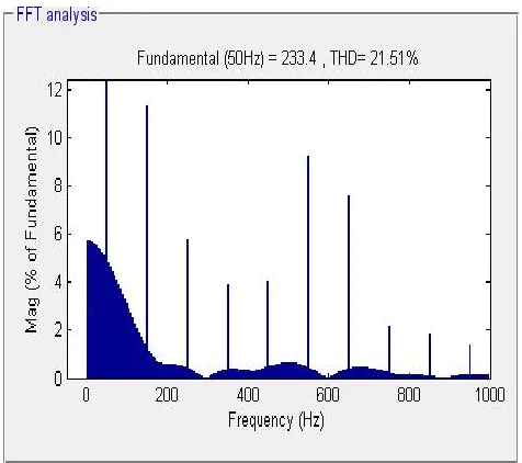
[image:6.612.49.287.443.654.2]The proposed model for switching the multilevel inverter with two unequal batteries as mentioned in the above mathematical equations, and FFT analysis of output voltage of the cascaded multilevel inverter as shown in fig6. The designed model was run for 10 seconds and the per phase output voltage waveform of multilevel inverter as shown in the fig 9.
Fig 5:MATLAB modeling of 3Ph 7-level cascaded multilevel inverter with two unequal dc sources
Fig6:FFT analysis of output voltage of the cascade multilevel inverter with unequal batteries
B.Multilevel inverter with two equal dc sources
3ph 7-level cascaded multilevel inverter model with two equal DC sources with the range of 100volts and load resistance of 100ohms was developed using simulink in MATLAB R2011b version as shown in fig 7. The proposed model for switching the multilevel inverter with two equal batteries as mentioned in the above mathematical equations, and FFT analysis of output voltage of the cascaded multilevel inverter as shown in fig8. The designed model was run for 10 seconds and the per phase output voltage waveform of multilevel inverter as shown in the fig 9.
Fig7: MATLAB modeling of 3ph 7level cascade multilevel inverter with equal dc sources
International Journal of Emerging Technology and Advanced Engineering
Website: www.ijetae.com (ISSN 2250-2459,ISO 9001:2008 Certified Journal, Volume 4, Issue 6, June 2014)
372
Simulink results for an 3ph 7level multilevel inverter operating with DC sources are shown in fig.9. The target harmonics were minimized with a THD (Total Harmonic Distortion) of 21.51% for multilevel inverter with unequal dc sources and 21.67% for multilevel inverter with equal dc sources.
Fig9:Per Phase output voltage waveform of Multilevel Inverter
IX. CONCLUSION
Elimination theory and the concept of resultants can be used to minimize the harmonics as well as overall THD of the output voltage of multilevel inverter with equal and also for unequal DC sources. A mathematical model of three-phase 7 level cascaded H-bridge multilevel inverter was developed and simulated using MATLAB. A seven level equal step output voltage switching control method was applied to multilevel inverters connected to the resistive load. The simulation results shows that the 7-level equal step output can be generated using two unequal battery sources instead of three equal battery sources.
The proposed scheme shows that H-bridge inverter with unequal battery sources requires less space and also it gives better performance.
REFERENCES
[1] J.chiasson, L.M. Tolbert, K.McKenzie, and Z.Du, “A complete solution to the harmonic elimination problem”, IEEE Trans. Power Electron., vol.19,no.2,pp.491-499,mar.2004
[2] John N. Chiasson, Leon M. Tolbert, Keith J. McKenzie, and Zhong Du,“Elimination of Harmonics in a Multilevel Converter Using the Theory of Symmetric Polynomials and Resultants” IEEE Transactions on control systems technology, vol. 13, no. 2, march 2005
[3] Jih-Sheng Lai and Fang Zheng Peng, “Multilevel Converters-A New Breed of Power Converters” IEEE Transactions on industry applications, vol. 32, no. 3, march 1996
[4] Leon M. Tolbert, John N. Chaisson, Zhong Du, Student Member, IEEE, and Keith J. Mckenzie, “Elimination of Harmonics in a Multilevel Converter with Non equal DC Sources” IEEE transactions on industry applications, vol. 41, no. 1, January/February
[5] Y.R.Manjunath, M.Y.Sanavullah, “Generation of Equal Step Multilevel Inverter Output using Two Unequal Batteries”. International Journal of Electrical & power Engineering.Vol.1 issue 2.2007. PP-206-209.
[6] D.Cox, J.Little, and D.O’Shea, Ideals, Varieties and Algorithms: “An Introduction to Computational Algebraic Geometry and Commutative Algebra”, 2nd ed.Berlin, Germany: Springer-verlag, 1996
[7] M.Hromcik and M.Sebek, “New algorithm for polynomial matrix determinant based on FFT,” in proc Eur.Conf.Control, ECC’99, Karlsruhe, Germany, Aug.1999, CD-ROM.
[8] “Numerical and symbolic computation of polynomial matrix determinant,” in Proc. Conf. Decision and Control, Tampa, FL, 1999, PP.1887-1888.
[9] T.Kailath, “Linear System”.Englewood Cliffs, NJ: Prentile-Hall, 1980.
[10] J.Von Zur Gathen and J.Gerhard, “Modern computer algebra”. Cambridge, U.K.: Cambridge Univ.press, 1999.