2019 International Conference on Artificial Intelligence and Computing Science (ICAICS 2019) ISBN: 978-1-60595-615-2
Crash Model Order Reduction for Efficient Topology Optimization
Using the ESLs Method
Chun
REN
1,2,*, Hai-tao MIN
2, Tian-fei MA
2and Fang-quan WANG
21Department of Mechanical and Transportation Engineering, Ordos Institute of
Technology Ordos, 017000, China
2State Key Laboratory of Automotive Simulation and Control, Jilin University,
Changchun, 130025, China
*Corresponding author
Keywords: Equivalent static loads method, Crash model order reduction method, Structural crashworthiness, Topology optimization.
Abstract. This paper presents an efficient structural topology optimization strategy for crashworthiness. The proposed method combines the equivalent static loads (ESLs) method with the crash model order reduction method. The ESLs method transforms crashworthiness topology optimization problems into a series of linear static topology problems. The crash model order reduction scheme is applicable to speed up the crash simulation. Therefore, the crashworthiness topology optimization is performed in a reduction manner and the efficiency is improved. The topology optimization results are filtered into a black-white design for the crash simulation to avoid the element distortion problem. The process is repeated until the convergence criteria is satisfied. The effectiveness of proposed method is demonstrated by investing a numerical example. The results show that, the proposed method can efficiently solve structural topology optimization problems for crashworthiness.
Introduction
dynamic problems into linear static problems. The mode reduction scheme is applicable to crash simulation to speed up the cycle of topology optimization under crash loads. The effectiveness of the proposed method is demonstrated by investing a numerical example and comparing with the results of the traditional ESLs method [15]. The results show that the proposed method has higher efficiency.
Theoretical Background
Crashworthiness Topology Optimization
The formulation of crashworthiness topology optimization is [16]:
n
find b: R (1)
min ( , N)
to :F b z (2)
: ( ) ( ) ( ) ( ) ( , ( )) ( )
( ), 1, ,
N N N N N
subject to M b z t C b z t K b z t z t
f t t l
+ +
= = (3)
N
(b, z (t)) 0, 1, ,
i
g i= m (4)
, , , 1, ,
L j j U j
b b b j= n (5)
wherebis the vector of the design variables;F b z( , N)is the objective function; Mis the mass matrix;
C is the damping matrix; Kis the stiffness matrix; f t
( )
is the external load vector at the tth timestep; andzN
( )
t and( )
N
z t
are the nodal velocity and acceleration vectors, respectively. In addition, the
subscriptNindicates that the response has nonlinear dynamic properties.bLjand Uj
b are the lower and
upper bounds of the jth design variablebj, respectively. Eq. (3) is the governing equation of nonlinear crash analysis, and the constantslandnare the number of the constraints and design variables, respectivelygjis the jth constrain.
The ESLs Method
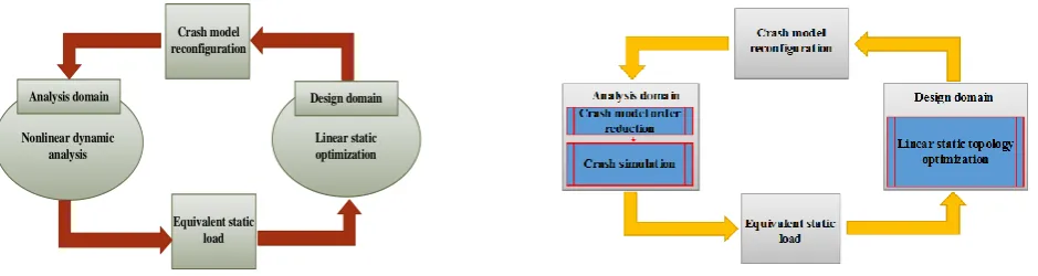
As illustrated in Fig.1, the traditional ESLs method for nonlinear dynamic response topology optimization is formulated as a sequence of cycles with four modules: nonlinear dynamic crash analysis, equivalent static load construction, topology optimization, and crash model reconfiguration. The detail of each module can be briefly described as follow.
Analysis domain Design domain
Nonlinear dynamic analysis
Linear static optimization
[image:2.595.72.542.611.736.2]Equivalent static load Crash model reconfiguration
Figure 1. Schematic flowchart of the traditional ESLs method. Figure 2. Schematic process of the proposed method.
Calculation of ESLs. The ESLs can be built by multiplying the linear stiffness matrixKL(b)to the displacement vectorzN( )t
( ) ( )
, 1, ,2 ,eq L N q
F =K b z t t=t t t (6)
wheretis the time steps of the dynamic process, and q is the total number of time steps during the crash analysis process.KL
( )
b is the linear stiffness matrix calculated by the linear elastic materialparameters.
Linear Static Topology Optimization. Under the ESLs, a topology optimization under crash loads can be convert to the sequence of linear static topology optimization problems.
: n
find bR (7)
( )
To min :F b (8)
s.t . :K Z sL ( )c =Feq( ) ,sc c= 1, ,q (9)
T f
v bv V (10)
min
0.0b bi 1.0, i= 1, ,n (11)
whereZ s
( )
c andFeq( )
sc are corresponding displacement vector and the ESLs vector at the time steprespectively. The static conditionscis strictly corresponding with the crucial time steptc. Vis the
total volume of the designable space,vfis the volume fraction andbminis the minimal element density
vector to avoid the numerical singularities.
Crash Model Reconfiguration. Direct employing the results of topology optimization for crash dynamic analysis will lead to mesh distortion phenomenon. To avoid this difficulty, the transformation variables were introduced. Transform the values of the design variables into the values of the transformation variables as follows:
1
1 0
: 1, , 1 i i e i where b i N where b = =
(12)
wherebiis the ith optimum design variable. iis the transformation variable forbi. The separation
parameter1is a certain value betweenbminand 1, which is defined by the user. If the value of a design variable is smaller than the separation parameter, the corresponding transformation variable has value of 0. Otherwise, the corresponding transformation variable is regard as 1. Through this operation, all the filtered zero density elements will be deleted and not incorporated into the crash dynamic analysis.
Existing Issues
The ESLs method provides a relatively feasible way to solve crashworthiness topology optimization problems. However, in structural crashworthiness topology optimization, the standard ESLs method is not efficient, since the whole model must be included in crash simulation, which make the optimization more expensive.
Proposed Method
the crash analysis is performed in a reduction manner to obtain the nonlinear response such as displacement, which is quite different from the traditional ESLs method (Fig. 1).
Crash Model Order Reduction
In the nonlinear FE method, with a discretization in space, a solid in a crash event is described by a system of ordinary differential equations with respect to time:
(
)
int ,
e e e e e
M +q h q t =h (13)
whereMeis the mass matrix, heint
(
q te,)
is the internal force vector andheis the applied forces. Crash simulations use explicit integration. One of the most-consuming parts of the explicit integration procedure is calculation of the internal and external forces on the element level in every time step. In general, the internal forces are a nonlinear function of the nodal displacements, nodal velocities and other variables. Under considerations, such as small displacements and liner elastic material laws, a linear FE approach is admissible. In a linear FE approach, the internal forces can be calculated byint
e e e
h =K q (14) whereKeis the linear stiffness matrix. In the presented simulation scenario, the small deformations
part is well approximated by a linearly reduced FE model. Therefore, it is necessary to linearize the nonlinear FE Equation (13) around a suitable working point.
( )
( )
( )
e e e e e
M q t +K q t =h t (15)
The global linear stiffness matrixKcan be obtained by assemblingKe. According to the static model order reduction theory, the reduced global stiffness matrix can be expressed as:
1
T
red mm sm ss sm
K =K −K K K− (16)
mm ms T ss ms K K K K K =
(17)
whereKis the global stiffness matrix andKmm,Kms,Kssare the submatrix with the corresponding
subscripts depicting the partitioning on the basis of the master DOFs and slave DOFs. Afterwards, the linearly reduced model of the linear part and the still nonlinearly described nonlinear part are assembled and simulated in LS_DYNA. Meanwhile, the typical responses, such as displacement, energy and acceleration are output.
Optimization Process
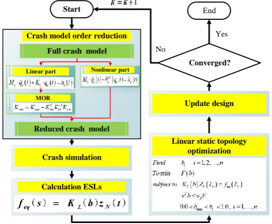
The process of the proposed method is shown in Fig. 3. The specific optimization process is as follows:
Step 1. Prepare the crash simulation model for topology optimization design;
Define the topology optimization problem, and initialize the pre-defined parameters such as volume fraction for the designable region.
Step 2. Crash model order reduction;
The full crash model is divided into linear and nonlinear parts. The identification of linear and nonlinear behavior could be performed by experienced user.
Step 3. The small deformation part of nonlinear FE model is linearized and corresponding linear stiffness matrix is exported;
Step 4. Linear model order reduction;
A program is developed to import the linearized stiffness matrix and perform linear model order reduction.
The reduced stiffness matrix is imported as a superelement and structural crash simulation is performed in a reduced manner. Then, the time step with the maximal internal energy is selected as the critical time steptc, and the corresponding displacement vectorzN( )tc is output.
Step 5. The ESLs are calculated;
Calculate the ESLs at the critical time step and serve as a condition of the linear static topology optimization.
Step 6. The topology optimization is performed;
The linear static response topology optimization is performed by using Eqs. (7–11), and the optimization design variables are obtained.
Step 7. Filter the topology optimization results and reconfigure the new crash simulation model; The FE model is reconfigured for crash dynamics analysis by using the filtered design variables in Eq. (12).
Step 8.Check if the optimization is converged, and repeat Steps 2-8 until converged;
If converged condition is satisfied, the optimization process is terminated; otherwise, k = +k 1and Step 2 is implemented.
Yes
No
Start End1
Nonlinear part Linear part
MOR
Full crash model
Reduced crash model Crash model order reduction
Crash simulation
Update design
Linear static topology optimization
1
Converged?
[image:5.595.157.425.287.508.2]Calculation ESLs
Figure 3. Flowchart of the proposed method.
Numerical Examples
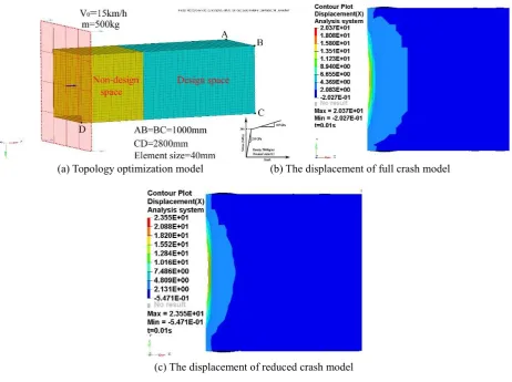
(a) Topology optimization model (b) The displacement of full crash model
[image:6.595.68.531.68.413.2](c) The displacement of reduced crash model
Figure 4. Topology optimization model and crash simulation results.
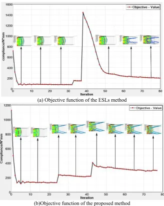
(a) Objective function of the ESLs method
[image:7.595.133.462.67.481.2](b)Objective function of the proposed method
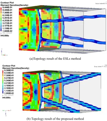
(a)Topology result of the ESLs method
[image:8.595.121.463.68.456.2](b) Topology result of the proposed method
[image:8.595.90.508.514.565.2]Figure 6. Topology optimization results of the first cycle.
Table 1. Comparison of optimization efficiency and convergence results.
Optimization
methods Iteration numbers The CPU time (s) Convergence results (N*mm)
ESLs method 80 778.9 221.2
Proposed method 77 719.5 297.5
Conclusion and Future Work
Acknowledgements
This article expresses gratitude to the Natural Science Foundation Project of Inner Mongolia Autonomous Region (No. 2017MS0520) and the Scientific Research Project of the Institution of Higher Education of Inner Mongolia Autonomous Region (No. NJZY17403).
References
[1] Fang, Jianguang, et al. “On design optimization for structural crashworthiness and its state of the art.” Structural and Multidisciplinary Optimization 55.3 (2017): 1091-1119.
[2] O'Neill, Brian. “Preventing passenger vehicle occupant injuries by vehicle design—a historical perspective from IIHS.” Traffic Injury Prevention 10.2 (2009): 113-126.
[3] Koffler, Christoph, and Klaus Rohde-Brandenburger. “On the calculation of fuel savings through lightweight design in automotive life cycle assessments.” The International Journal of Life Cycle Assessment 15.1 (2010): 128.
[4] Patel, Neal M., et al. “Crashworthiness design using topology optimization.” Journal of Mechanical Design 131.6 (2009): 061013.
[5] Sun, Guangyong, et al. “An experimental and numerical study on quasi-static and dynamic crashing behaviors for tailor rolled blank (TRB) structures.” Materials & Design 118 (2017): 175-197.
[6] Fehr, Jörg, Philip Holzwarth, and Peter Eberhard. “Interface and model reduction for efficient explicit simulations-a case study with nonlinear vehicle crash models.” Mathematical and Computer Modelling of Dynamical Systems 22.4 (2016): 380-396.
[7] Lee, Jaehun, and Maenghyo Cho. “Efficient design optimization strategy for structural dynamic systems using a reduced basis method combined with an equivalent static load.” Structural and Multidisciplinary Optimization (2018): 1-16.
[8] Schilders, Wilhelmus HA, Henk A. Van der Vorst, and Joost Rommes. Model order reduction: theory, research aspects and applications. Vol. 13. Berlin: Springer, 2008.
[9] Benner, Peter, Volker Mehrmann, and Danny C. Sorensen. Dimension reduction of large-scale systems. Vol. 35. Springer-Verlag Berlin Heidelberg, 2005.
[10]Antoulas, Athanasios C. Approximation of large-scale dynamical systems. Vol. 6. Siam, 2005.
[11]Quarteroni, Alfio. Reduced order methods for modeling and computational reduction. Ed. Gianluigi Rozza. Vol. 9. Berlin: Springer, 2014.
[12]Miled, Bilel, David Ryckelynck, and Sabine Cantournet. “A priori hyper-reduction method for coupled viscoelastic–viscoplastic composites.” Computers & Structures 119 (2013): 95-103.
[13]Farhat, Charbel, et al. “Dimensional reduction of nonlinear finite element dynamic models with finite rotations and energy‐based mesh sampling and weighting for computational efficiency.” International Journal for Numerical Methods in Engineering 98.9 (2014): 625-662.
[14]Fehr, Jörg, and Dennis Grunert. “Model reduction and clustering techniques for crash simulations.” PAMM 15.1 (2015): 125-126.
[15]Kim, et al. “Nonlinear dynamic response structural optimization using equivalent static loads.” Computer Methods in Applied Mechanics & Engineering 199.9(2010): 660-676.