un
Digital
Microsystems
TMHINET
PROGRAMMERS
MANUAL
Digital
Microsystems
UJ) '"
PROGRAMMER'S MANUAL
Version 1.0
COPYRIGHT
All rights reserved. No part of this manual may be reproduced without the prior written permission of Digital Microsystems, Inc.
Digital Microsystems
1755 Embarcadero, Oakland, CA 94606 (415) 532-3686 lWX 910-366-7310
NOTICE
Digital Microsystems, Inc. reserves the right to make improvet1)ents to the products described in this manual at any time, without notice.
TRADEMARKS
HiNet, HloOS, oMS-816, oMS-15, DMS-3/F, DMS-1280, DMS-3/4, oMS-5000, oMS-38 are trademarks of Digital Microsystems, Inc. CP/M and CP/M-86 are trademarks of Digital Research, Inc. MS-DOS is a trademark of Microsoft Inc. IBM, IBM-PC and PC-MS-DOS are trademarks of International Business Machines, Inc.
HINET PRCX:lRAMMER'S MANUAL TABLE OF CONTENTS
TABLE OF CONTENTS
1.0 INTRODUCTION. • •
. . .
.
. . .
12 • 0 NE'IWORK PROTOCOLS • • • • • • • 2.1 NETWORK TRANSMISSION FORMAT. 2.2 HINET ~STER FUNCTIONS •
1
2 4 8
8 9
2.3 TABLES AND BUFFERS • • • 2.3.1 WHO TABLE • • • • 2.3.2 SPOOL FILE TABLE. 2.3.3 LOCK TABLE. • • • • 2.3.4 MASTER BUFFER • • • 2. 3.5 FLOPPY WRITE BUFFER • •
2.3.6 FLOPPY READ BUFFER • • • • • • • 2.3.7 HARD DISK TRACK AND SECTOR LAYOUT • 2.3.8 LAYOUT OF HARD DISK PARTITION ZERO.
10
11 11 11 11
14
HINET PR(x;RAMMER'S MANUAL TABLE OF CONTENTS
4.0 DMS-816 IBM ROM BIOS EMULATION.
· ·
·
·
· ·
75 4.1 INTRODUCTION •· · ·
· ·
·
·
· ·
·
·
75 4.2 PRINT SCREEN • • • • • • •· . . .
75 4.3 TIMER INTERRUPT.· · · ·
76 4.4 TIME OF DAY.·
·
·
· ·
· · · ·
76 4.5 DMS-816 VIDEO ROUTINES •·
774.6 EQUI PMENT CHOCK.
·
·
· ·
·
79 4.7 MEMORY SIZE DETERMINATION.·
·
·
·
80 4.8 DISKETTE I/O •·
·
·
·
·
·
81 4.9 COMMUNICATIONS (RS-232)·
·
·
·
824.10 KEYBOARD.
. · · ·
844.11 PRINTER •
. · ·
·
· · ·
·
· ·
·
· ·
85 4.12 BOOTSTRAP (COLD BOOT)·
· · ·
·
·
·
86 4.13 OMS 816 10 ADDRESSING •·
·
87 4.14 DMS-816 Z-80 I/O OPERATIONS • 90 4.15 DMS-816 CENTRONICS INTERFACE. • •••• 90 4.16 PR(X;RAMMING FUNCTION KEYS •· ·
·
·
905.0 SHARING PARTITIONS UNDER HIDOS • • • • 95 5.1 USING HIDOS--LIMITS AND RESTRICTIONS 96 5.2 FILE AND RECORD LOCKING • • • • • • 98 5.3 ROCORD LOCKING PROCEDURES • • • • • •• 99 5.4 DATA RECORD SIZE VS. CP/M RECORD SIZE. • 100 5.5 CALCULATION OF CP/M RECORDS • • • • • • 104 5.6 HINET BIOS LOCK AND UNLOCK • •• • • • • 107 5.7 8088/8086 ROCORD LOCKING • • • • • • • • 111 5.7.1 INTERRUPT 78 TO CALL MACHINE BIOS • 111 5.7.2 FUNCTION CALLS FOR RECORD LOCKING. 112
6.0 THE NETWORK BUFFER • • • • • • • • • • • • 115
7.0 INTERSTATION COMMUNICATIONS • • • • • • • • 118 7.1 THE POLL-PRIME DATA BLOCK • • • • • • • 121 7.2 RECEIVING POLL-PRIMES • • • • • • • • • 122 7.3 MS-DOS CONSIDERATIONS • • • • • • • • • 123 7.4 SENDING POLL-PRIMES FROM A Z-80 STATION 124
HINET PROGRAMMER'S MANUAL 1.0 INTRODUCTION
1.0 INTRODUCTION
HiNet is a Local Area Network developed by Digital Microsystems. It links Z-80 and 8086/88 based microcomputers to centralized Hard Disk Storage and shared printers (via a high-speed print spooler). Local Hard Disk and Floppy Disk storage is available with two of the workstations. Several types of IBM PC compatible microcomputers can also be linked to the Network through a Z-80 based Hi Net J\dapter Card. MS-OOS, CP/M-86 and HIDOS (enhanced CP/M-80) operating systems can
be run on the Network.
This Programmer's Manual is for anyone desiring to design or adapt programs and systems
to work with HiNet. The basics of HiNet--its operation and utilities--are presented in DMS manuals for each workstation and the HiNet
Master Manual. Some proprietary information that may be necessary to alter the BIOS is not
included in this document. This information may
be obtained from Digital Microsystems through a
special licensing agreement.
-2.0 NETWORK PROTOCOLS
HINET PROGRAMMER'S MANUAL 2.0 NETWORK PROTOCOLS
you better understand HiNet and its BIOS Interface, the basic Network protocols are briefly presented in this section.
2.1 NE"1'WORK TlWHfiSSION FOBHA'l'
Each transmission on the Network is done in Synchronous Data Link Control (SOLC) format. SOLC was introduced by IBM for computer-to-computer communication. It was chosen for HiNet primarily because the widely available Zilog SIO chip implements most of the details of SOLC transmission and reception. The HiNet system automatically programs the SIO and OMA chips to send or receive blocks of data appropriately.
Each SOLC transmission has the following format:
I
FlagI
UserI
Data bytesI
CRC bytesI
FlagI
byte number. (1 to 1024 bytes) (2 bytes) . byteField Description
Flag byte A flag byte is the bit sequence '01111110'. At least two flag bytes surround each transmission. The SOLC standard requires a minimum of one flag byte before and after each transmission. However, HiNet forces several flag bytes at both ends because it is suspected that the SIO chip has a bug which causes it to miss a flag occasionally.
HINET PROGRAMMER'S MANUAL 2.0 NETWORK PROTOCOLS
User number
Data bytes
CRC bytes
Each station is assigned a unique identification number, a user number, when it logs in. Each arrl every transmission to a station must
include its user number. The Master is always assigned user nliffiber
.2.t.
while all other stations are assIgned numbers from 1 to 63. User numbers 251 thru 254 are reserved for special purposes, which are described in Section 2.One or more bytes can be transmitted in the data portion of an SDLC
transmission. In HiNet, the data bytes may specify a commarrl, a
response, or data to be read from or written to the Master disk.
Each transmission is terminated by 16 bits of error-check information. These bits are computed when data is transm i tted arrl are re-computed when data is received. If an error occurs in the middle of a transmission, the usual result is a detectable
cae
error. HiNet will retry any Network transmission which has a CRC error.
Whenever it observes five consecutive ones in the data stream, the SIO chip inserts a zero bit automatically. These extraneous zero bits are removed by the receiving SIO chip. This zero-insertion method allows the chip to recognize flags, and thus to identify the
HINET PROGRAMMER'S MANUAL 2.0 NETWORK PROTOCOLS
2.2 BINET KASTER FUNCTIONS
On the Master station, the basic control loop is as follows:
1. The Master process is invoked each clock tick (usually 62 hertz). When the local user (commands from the t-1aster's console) engages a private Floppy Disk operation, the Master process is delayed until the next clock tick. This is necessary because the DMA chip is shared by floppy and Network operations.
2. The Master polls each active user after invocation. Active users can respond with one of the commands listed below. All users that have acknowledged the Master's previous poll are active. A poll is a one byte command (SOh). All Network transmissions are done in SOLC format, so the poll is actually preceded by the one-byte destination user number.
Description of HiNet Caamand
Acknowledge ••••••• 4lh Get who table ••••• 10h Read 128 bytes •••• 11h Read 1024 bytes ••• 15h Write 128 bytes ••• 12h Start spool file •• l4h Spool 128 bytes ••• lCh End spool file •••• 16h Assign partition •• 17h Hog the Network ••• 18h Poll-Prime •••••••• 55h LOck record ••••••• 19h
Release: 12/1/84
1 byte 1 byte 8 bytes 8 bytes 8 bytes 2 bytes 8 bytes 2 bytes 15 bytes 1 byte 1 byte 15 bytes
1\dditional caaaard
paraneters
•• dtn,src,dsk,trk,sec,vli •• dtn,src,dsk,trk,sec,vli •• dtn,src,dsk,trk,sec,vli •• sid
•• dtn,src,dsk,trk,sec,vli sid
nam,psw
len,lck
HINET PROGRAMMER'S MANUAL 2.0 NETWORK PROTOCOLS
Description of HiNet Cmman:J
Add i tional CCJIIIIilfld
parameters
Unlock record lAil Clear all locks ••• IBh Get HD status ••••• IDh Get date time ••••• lEh
15 bytes 1 byte 1 byte 1 byte
len,lck
Login ••••••••••••• 13h Instant logout •••• IFh Write Modes ••••••• 20h Network info •••••• 21h
20 bytes 2 bytes 6 bytes 1 byte
usr,psw,ser#,prod src
wmc,vli,dsk,val,usr
Cmman:J
Par<meters
dtn = destination station number (always 0) ••••••••••• src = source station number (sane as user number) ••••• dsk = partition number (0-63) ••••••••••••••••••••••••• trk = track number (0-511) •••••••••••••••••••••••••••• sec
=
sector number (1-128) ••••••••••••••••••••••••••• vIi = vo1une number (0-3) ••••••••••••••••••••••••••••• nam = partition namE ••••••••••••••••••••••••••••••••••usr = user name ••••••••••••••••••••••••••••••••••••••• psw = password •••••••••••••••••••••••••••••••••••••••• len = length of lock string (1-13) •••••••••••••••••••• lck = lock str ing •••••••••••••••••••••••••••••••••••••• wmc = write mode command (grt/re1/frc/qry) •••••••••••• val write mode force value or logical user number ••• usr write mode physical user number ••••••••••••••••• sid spool job id number •••••••••••••••••••••••••••••
1 byte 1 b~te
1 byte 2 bytes 1 byte 1 byte 8 bytes 8 bytes 6 bytes 1 byte 13 bytes
HINET PRQGRAMMERi S MANUAL 2.0 NE'n«>RK PROTOCOLS
---~---~---Normally there is no need for an applications programmer to use these HiNet commaoos directly. The sections on the HiNet BIOS Calls and
Interstation Communication explain the calls that will perform the above functions for the applications. program.
3. If
a
user respooos to a poll with an"acknowledge" commaoo, then no further interac-tion with the user will be contemplated until
the Master process re-awakes on the next clock tick. All other commaoos require an interchange of information between the Master and the User Station, as described in Section 3.0.
4. A user station is polled at the normal polling rate 160 times. The station then becomes a 'slow user' and is polled at 1/12 the normal polling rate for an additional 96 times. A user that respooos to any of these polls regains normal status; otherwise, the user is logged out. When a user is logged out his or her user number aoo all locks are released. If a spool file is being created, it is erased. If the user owns any partitioris,they are released. 5. After polling all active users, the Master checks the local user for pending requests. If a request is pending, the local user's Network commaoo byte will be non-zero. Pending requests are processed, and their commaoo bytes are set to zero, signaling command completion.
6. The Z-80 Network station bootstrap code is transmitted pericrlicaUy (once per polling loop
HINET PROGRAMMER'S MANUAL 2.0 NE'lW)RK PROTOCOLS
am about once per secom) to pseudo-user 254. The PROM at each Z-80 station has been programma:! to receive 380h bytes addressa:! to 254's user number so that it can boot from the Network. The bootstrap code is loada:! into memory at location 9000h, and executed. This boot code displays the "HiNet 2.2xx" message, waits for a poll of pseudo-user 253, am attempts to log in by PROM serial number. The 8086/8088 Network station PROM contains sufficient code to attempt the login by PROM serial number directly.
7. The Master polls pseudo-user 253 periodi-cally (once per pollirlJ loop am about once per secom). Any station that wants to connect to HiNet must respom to the user 253 poll with a series of interactions.
• The station sems the PROM serial number in ASCII, the serial number in binary, am product type to the Master.
• The Master accepts the login request uncomitionally am responds with a unique user number, the login time, am the binary serial number.
• The Master consults the Machine table, product Type table, and User table on the Hard Disk for a matchirlJ ASCII PROM serial number, am product type.
HINET PROGRAMMER'S MANUAL 2.0 NETmRK PROTOCOLS
---• If the PROM Serial Number is not foum in the USER Table, Boot Phase 2 loads the Login Please program into the station. This allows the user to enter a specific name am password that is stored in the USER Table. What is then sent to the station depends on whether the name/pass-word was found in the User table and on the Network station's product type.
8. The Master polls pseudo-user 252 once per Master pollirg loop. A mimickirg system (if any) must respond to these polls to come on-line and remain on-line.
9. The Master checks regularly (once every pollirg loop am also about once per secom) whether the spool print buffer is empty and needs to be refilled. If so, the next sector of the printing spool file is read, and printing is restarted. If not, the spooler checks whether a new spool file should be opened and printed.
The followirg section details the various tables and buffers that are maintained in the Master.
2.3 TABLES AND BUFFERS
2.3.1 WHO TABLE
The who command can be used by any station to determine who is currently logged into HiNet, and who has active spool files.
[image:13.402.19.351.47.599.2]HINET PROGRAMMER'S MANUAL 2.0 NE'IW)RK PROTOCOLS
The Who Table has either 32 or 64 entries, each 16 bytes long. The first byte of the return
with a GETWHO irrlicates the maximum number of users. This value is also returned by NetInfo. Each entry corresporrls to a single user. The first entry describes user 0 (the Master user); the remaining entries describe users 1 to 31 or 63. The NetInfo protocol outlined later on in this document may also be use:] to determine the maximum number of users. Each entry contains the following information:
FORMAT of WHO INFORMATION:
1 byte - max number of users on system (32 or 64) 16 byte entries
*
max users - USER ENTRIES256 bytes (16 bytes
*
16 entries) - SPOOL ENTRIESFORMAT of User Entry:
1 byte - Activity count. OFFh - active
o
-
deadother - logg ing out
8 bytes - User Name.
3 bytes - login time (secs,mins,hours)
3 bytes - last request time (secs,mins,hours) 1 byte - last request command byte.
2.3.2 SPOOL FILE TABLE
The spool table has 16 entries (the value currently returned by NetInfo), each 16 bytes long. Each entry corresporrls to a single spool file. Each entry contains the following
HINET PROGRAMMER'S MANUAL 2.0 NE'JW)RK PROTOCOLS
1 byte - spool status 0 - starting spool 1 - spooling
2 - ready to print 3 - printing
4 - stop print 5 - waiting
OE5h - aborted or done
1 byte - user number of User spooling. 1 byte - spool ID (top nibble job i,
low nibble block i). 2 bytes - time job started (min,hour). 2 bytes - track i of last sector of job. 1 byte - sector # of last sector of job. 8 bytes - spooler's name.
2.3.3 LOCK TABLE
Each lockstring is described by a l6-byte entry. The first byte is the number of the user who created the lock. If the entry is not in use, the first byte is OFFh. The next byte is the lockstring length. '!be next 13 bytes are the lockstring. The last byte is not userl.
/1 byte / 1 byte
I
13 bytes11
byteI
user name lockstnng
I .
length of lockstring not used
See sections 3.0 and 5.0 for more information on lockstrings.
HINET PROGRAMMER'S MANUAL 2.0 NETWORK PROTOCOLS
2.3.4 KASTER BUFFER
This is a general buffer for the Master's use. However, not all Hard Disk I/O operations use this buffer. It is located 400h bytes below the Who Table.
2.3.5 FLOPPY WRITE BUFFER
This optional buffer resides 100h bytes below Hard Disk buffer. This buffer is used for all double-density floppy write operations.
2.3.6 FLOPPY READ BUFFER
This optional buffer resides 100h bytes below write buffer. It is used for all double-densi ty floppy recrl operations.
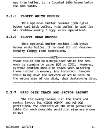
---NOTE---These tables can be manipulated while the Net-work is running by using DDT or ZDTI. However, extreme caution should be taken when altering these tables in memory. Any incorrect changes could bring down the Network or write data to the wrong area of the disk, thus destroying data.
2.3.7 HARD DISK TRACK AND SECTOR LAYOUT
[image:16.398.43.380.143.590.2]HINET PR(x;RAMMER ' S MANUAL 2.0 NETWORK PROTOCOLS
CP/M 2.2 Disk Paraneters
Sectors per track Block sh i ft, mask Block count - 1 Directory count -Directory blocks Check vector size**
Op sys tracks
Sectors per track Blockshift,mask Block count - 1 Directory count -Directory blocks eheck vector size**
Op sys tracks
256K 128 3,7,0 255 163 OeOOOh 16 0 4MEG 128 4,15,0 2047 1023 OFFFEh 256
o
512K lMEG 128 128
4,15,0 4,15,0 255 127 OeOOOh 32 0 8 MEG 128 5,31,1 2047 1023 OFFOOh 256
o
511 255 OFOOOh 64 0 16 MEG 128 6,63,3 2047· 1023 OFOOOh 256o
2~1EG 128 4,15,0 1023 511 OFFOOh 128 0 32MEG 128 7,127,7 2047 1023 OeOOOh 256o
**
HiDOs does not allocate check vectors, size = O. ep/M FLOPPY DISK rAYOUTSectors per track Blockshift, mask Block count - 1 Directory count -Directory blocks eheck vector size
Op sys tracks
Release: 12/1/84 1
a"
Floppy Sin:Jle Density 26 3,7,0 242 63 OeOOOh 16 2a"
Floppy 5.25"DOuble DOuble-Sided Density Floppy
52 32
4,15,0 5,31,0
242 156
127 127
OeOOOh 08000h
32 32
2 3
HINET PR(x;RAMMER' S MANUAL
- - - - -
2.0 NETW)RK PROTOCOLSt&-DOO DISK PARAMETERS
256K 512K 1MEG 2t1ill Bytes per sector 128 128. 128 128 Sectors per cluster 8 8 8 16 Reserved sectors 1 1 1 1
No. FATs 2 2 2 2
Root dir entries 256 256 256 512 No. sectors 2048 4096 8192 16384
Media byte 0 1 2 3
Sectors per FAT 3 6 12 12 Sectors per track 128 128 128 128
4MEX.> 8MEX.> 16MEX.> 32MEG Bytes per sector 128 128 256 512 Sectors per cluster 16 32 32 32 Reserved sectors 1 1 1 1
No. FATs 2 2 2 2
Root dir entries 1020 1020 1020 1020 No. sectors 32768 65535 65535 65535
Media byte 4 5 6 7
Sectors per FAT 24 24 12 6 Sectors per track 128 128 64 32
HINET PROGRAMMER I S MANUAL 2.0 NETWORK PROTOCOLS
2.3.8 LAYOUT OF HARD DISK PARTITION ZERO
Tracks and Sectors are CP/M Logical, not physical.
______________________
~---.-rtrack 0, sectors Ol-lFlt Controller Program track 0, sectors 20-28
fA.
reserved for expansion of controller program track 0, sectors
29-38~
HiNet User Name Table Up to 128 16-byte entries:
track 0, sectors
39-78~
HiNet User Configuration Table Up to 128
8 bytes: 8 bytes: 8 bytes: 8 bytes: 1 byte: 31 bytes:
64-byte entries: defaul t A dr i ve default B drive defaul t C dr i ve default D drive length of typeahead typeahead buffer track 0, sectors 79-80
iA
Disk Allocation Table
HINET PROGRAMMER'S MANUAL 2.0 NETWORK PROTOCOLS
track 1, sectors 01-08 Bad Sector Table
Up to 64, 128, or 256 3-byte entries depending on drive type:
1 byte: track 1 byte: head 1 byte: sector track 1, sectors 09-14
Machine Table Up to 128 4 bytes: 1 byte: 6 bytes: 1 byte:
12-byte entries: Serial Number Product Number Option Map roBYTE track 1, sectors 15-16
~Yr i te Mode Table track 1, sector 17
reserverl track 1, sector 18
Reserverl
track 1, sectors 19-20: product Type Table Up to 40
1 byte: 8 bytes: 8 bytes: 8 bytes:
25-byte entries: Product Type
Boot Phase 2 program name Login please program name
HINET PROGRAMMER'S MANUAL 2.0 NETWORK PROTOCOLS
track 1, sectors 21-80:
Operating System Table
Up to 128 1 byte: 16 bytes:
6 bytes: 64 bytes: 9 bytes:
96-byte entries: OS nunber
Product Map
Option Map
LOad List (8 names of 8 bytes)
--reserved--track 2, sectors 01-02 Cold Boot Loader
track 2, sectors 03-08
reserved for use of Cold Boot Loader
track 2, sectors 09-20 System Directory
Up to 128
8 bytes:
5 bytes: 2 bytes: 4 bytes: 2 bytes: 1 byte: 2 bytes:
24-byte entries:
File Name
Disk Address
Length (128-byte records) Load Address
Execution Address Offset programVData flag
-reserved--track 2, sectors 21-80 -- Reserved
Remainder of partition allocated according to contents of the System Directory.
HINET PROGRM~R'S MANUAL 3.0 HINET BIOS INTERFACE
3.0 THE HINET BIOS INTERFACE
The HiNet BIOS has several routines which can be called from a user program to send or receive data over the HiNet cable. utility programs such as WHO, DIRNET, and ASSIGN use these routines to interface with HiNet. On Z-80s
all four routines are accessible though jump vectors at fixed offsets from the base of the BIOS; on 8086/88s through BOOS Call 50 or
Interrupt 78; under r1S-DOS, the network calls must be accessed with INI' 78 and the MACHINE BIOS Number.
Offset Name Description
6Fh
Input:
72h
Input:
SENDNET
HL= Be= E = A =
RECNET
Transmit a block of data on the Network.
address of data to be transmitted number of data bytes
pre-transmission delay (Master only) user number of intended recipient
Receive a block of data fram the Network.
HL = address where data is to be stored Be = maximum number of data bytes DE = timeout delay (Master only) A
=
user number of recipientOutput: A = resul t status
bit7 =0 if timeout (block not received) = 1 if block received
HINET PROGRAMMER'S MANUAL 3.0 HINET BIOS INTERFACE
=
1 bit 5=
0= 1
i f CRC error
if no receiver overrun if receiver overrun
Stations Only> bit 0
=
0= 1
if a valid poll was not received if a valid poll was received
User station only
75h NACKPOLL wait for next poll, then deactivate automatic poll acknowledgments.
output: A
=
result status (same as RECNET)Master station only
75h INTERCEPI' Intercept and process a command from a user station. .
Input: HL
=
address of HiNet commandoutput: A
=
0 if OK, non-zero if errorHINET BIOS JUMP VECTORS:
User station only:
78h ACKPOLL Reactivate automatic poll acknowledgments.
Master station only:
78h INTERRUPI' Process a one-second interrupt.
84h HDstat Check status of local hard disk.
User station only:
87h HDstat Check status of Network volume(s).
HINET PROGRAr1MER'S MANUAL 3.0 HItlET BIOS INTERFACE
Programs at any station other than the Master can communicate on the Network by calling the ACKPOLL routine first (to synchronize in case of a previous error), then the NACKPOLL routine. NACKPOLL either receives a poll or returns to the user after a four-second wait. When no poll is received NACKPOLL returns with an error status in A.
The proper way to test status is to test each bit individually, or AND the returned value with the significant status bits: OE1h, and test for poll received with no error: 8lh. When a poll is received, the program can then call SENDNETiind RECNET to complete the desired transaction. When the transaction has been completed, the program should call ACKPOLL. ACKPOLL will force the BIOS to acknowledge polls automatically until NACKPOLL is called again.
When using SENDNET or RECNET at a user station, one does not need to specify a pre-transmission or timeout delay. The pretransmis-sion delay will always be 500 microseconds while the timeout delay will a1 ways be about four seconds. The pretransmission delay should give the intended recipient of a message more than enough time to reprogram the DMA and S10 chips. FOr example, even if several interrupts (timer, spooler) occur while the chips are beiD:J
HINET PROGRAMMER'S MANUAL 3.0 HINET BIOS INTERFACE
The INTERCEPT arrl INTERRUPT jump vectors are available only on the Master. The Master calls the INTERCEPT routine through the jump vector whenever it receives a command from a user station which has a commarrl byte of O. (The first byte of a commarrl is called the "command byte".) Commarrls can be up to 15 characters long, including the commarrl byte. By replacing the INTERCEPT jump vector, users can supply their own command processing routine to communicate directly with the Master station programs, other user stations, or anything they choose to do through their applications program.
The code to replace the jump vector might look something like this:
di don't allow interrupts while changing lhld 1 get address of base of BIOS + 3 lxi D,73h ; offset of INTERCEPT address
dad D compute address of INTERCEPT vector lxi D,INTERCEPT
mov M,E replace low byte of INTERCEPT vector
inx H
mov M,D replace high byte of INTERCEPT vector ei ; interrupts OK now
; Here is the new INTERCEPT routine INTERCEPT:
mov a,m ora a
ensure first commarrl byte was zero mvi a,Offh
rnz inx H mov A,M
sub A
ret
ret a = Offh i f command wasn't zero skip first command byte
; look at secorrl byte of commarrl ; return status of OK (non-zero
if error)
HINET PROGRAMMER'S MANUAL 3.0 HINET BIOS INTERFACE
Note that the INTERCEPT routine is invoked also by the Master for illegal commands; so, the user should return a = ffh for any non-zero comnam.
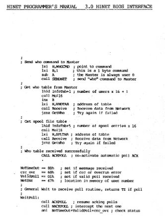
The following example is an assembly language program which shows how a user station can access the WHO Table and the SPOOL Table. Both are maintained by the Master. These tables can be used to determine who is logged into the Network, am what each current user is doing. Note, the user number is stored in the same location at every Z-80 station: 47H. The User Number should be used to communicate with the Master; it should never be changed once the station has logged onto the Network.
;
; Determine size of who table BeginWho:
call WaitPOll ; wait for Network poll jrnz BeginWho ; start over again if error
lxi H,Netlnfo; point to command lxi B,l ; one byte cannam sub A ; master is user 0
. call SENONET sem Netlnfo to Master
lxi H,InfoTab; place to store Net Info table lxi B,128 ; leDJth of table
call Receive ; Receive fran Network jrnz BeginWho i Try again if failed
Now set up to get W10 table
call Wai tPOll
..:,:H:.:::.IN::.::E::::T:-.::P..:.:R:::::OG;:::RAMME::.:::..:.=:.::R:....;' S=-.:.MANU==AL=--~3. 0 HINET BIOS INTERFACE
SeOO who command to Master
lxi H,WHOCMD ; point to commarrl lxi B,l ; this is a 1 byte commarrl sub A ; the Master is always user 0 call SENDNET ; serrl "who" commarrl to Master
Get who table from Master
lhld InfoTab+l ; number of users x 16 + I
call Mull6
inx B
lx i H. WH<Yl'AB call Receive jrnz Getl'h>
Get spool file table lhld InfoTab+5 call Mull6 lxi H,SPLTAB call Receive jrnz Get~o
address of table
Receive data fran Network Try again if failed
; number of spool entries x 16
address of table
Receive data fran Network Try again i f failed
~o table received successfully
CALL J\CKPOLL ; re-activate automatic poll J\CK
NoTimeout-=<= SOh
==
60hOlh
47h
set if message received crc ovr
valTdPOll NetUsr
;
set if crc or overrun error set if valid poll received location in memory of user number
; General wait to receive poll routine, returns TZ if poll
;
waitPOll:
call ACKPOLL ; resume acking polls call NACKPOLL ; intercept the ne)Ct one
ani NoTimeout+ValidPOll+crc ovr ; check status
[image:27.401.20.353.47.482.2]HINET PROGRAMMER'S MANUAL 3.0 HINET BIOS INTERFACE
cpi NoTUneout+ValidPoII
rz return if succeeded
push PSW call lICKroIL mvi C,conouts lxi D,NOroIL call BOOS pop PSN ret
save error status for analysis resume automatic poll acknowlegement poll not received, so •••
print error message
use the BOOS print function return A reg aoo FZ
General Receive Network routine, returns TZ if receive OK
;
Receive:
Ida NetUsr ; this station's user number at 47H call ROCNET
ani NoTllneOut+ValidPoII+crc ovr ; check status cpi NoTUneout should get non-poll msg rec'd rz return if succeeded
push PSN save error status for analysis mvi c,conouts
lxi d,xmitFailed call BOOS
pop PSN ; return A reg aOO FZ ret
Multiply L register by 16 and move result to Be Mul16:
mvi H,O dad H dad H dad H dad H push H pop B ret
zero upper byte
multiply by adding to self 4x
HlNET PROGRAMMER'S MANUAL 3.0 HINET BIOS INTERFACE
3.1 BINET BIOS CALLS
3.1.1 INTRODUCTION
Since the BIOS is specifically tailored to DMS hardware, programmer's should use the
appropriate BIOS Calls whenever possible instead of writing to the hardware or using specific addresses in the BIOS. This section explains in detail the available calls to the BIOS. Section 4 details the BIOS Calls for the DMS-816's IBM ROM BIOS emulation.
3.1.2 Z-80 BIOS CALLS
To make a BIOS calIon Z-80 stations, the BIOS function number is converted to an.offset and the offset is added to the start of the BIOS Jump Vector. It is up to the application program to save any registers that may be destroyed by the BIOS. This method of calling the BIOS is demonstrated in the following example.
BOOT
BIOS
equ equ
OOOOOh OOOOlh
bioscall: ;given N
=
BIOS function number and ;all registers stuffed for the ifunction being called, this iroutine will call the BIOS. ;ZILOG mnemonics TDL mnemonicspush IX push X
push DE push D
1d DE, (3
*
N) lxi D, (3*
N)HINET PROGRAMMER'S MANUAL 3.0 HINET BIOS INTERFACE
ld IX, (BIOS) lixd BIOS
add IX,DE dadx D
pop DE pop D
call jmpbios call jmpbios
pop IX pop X
ret ret
jrnpbios: icallerl to force a return address on ;the stack
jp (IX) pcix
Function numbers 0 through 15 are standard to CP/M-80i they are handled exactly as documented
in Digital Research's CP/M Operating System Manual. BIOS Function Numbers 30 through 49 are calls that are specific to Digital Microsystems' BIOS and should be used according to the above example. Each call is documented in the
HINET PROGRAMMER'S MANUAL 3.0 HINET BIOS INTERFACE
Bloo Function NuDbers
CPM-80 CPM-86 COMMON (BOOS 50) (INT 78) BIOS Function function :It function :It function :It
Cold Boot -1 0 50
Wann Boot 0 1
Console Status 1 2 0
Console Flush 1
Console Input 2 3 2
Console Output 3 4 3
List Output 4 5 5
punch Output 5 6
Reader Input 6 7
Aux Status 6
Aux Flush 7
Aux Input 8
Aux Output 9
H~E disk 7 8
Select disk 8 9
Set Track 9 10
Set Record 10 11
Set DMA offset 11 12
Read Record 12 13 10
write Record 13 14 11
List Status 14 15 4
Get MEmory size 12
Media Same 13
Spool Flush 14
Set I/O pointer 15
HINET PROGRAMMER'S MANUAL 3.0 HINET BIOS INTERFACE
BIOS Function function It function It function It
CPM-80 CPM-86 COMMON (BOOS 50) (INT 78)
Clear Locks 16
Aux Status 1 17
Record Translation 15 16
Set DMA segment 17
Get Segment Table 18
Get I/O byte 19 19
SRI' I/O byte 20 20
Make Assigrment 21 21
Get Assigrrnent 22 22
Set/reset visible
error flag 25 24
Get Error Count 26 25
Set/reset Retry flag 27 26
WHO request 28 27
DIRNET request 29 28
Flush Flop Buff 30
Net Lock 31 30 29
CP/M MAP 32
Net Unlock 33 31 30
Coerce 32 31
Set I/O byte count 34 Version (location of) 35
SENDNET/srrlnet 36 38 37
RECNET/rcvnet 37 39 38
NACKPOLL/clrpo1 38 37 36
ACKPOLL/setpol 39 36 35
'USER' port output 40
Set Poll-prbne address 41 33 32 Set Receive timeout 42
Local Hard Disk Status 43
HINET PROGRAMMER'S MANUAL 3.0 HINET BIOS INTERFACE
BIOS Function function #
CPM-80
function #
CPM-86 (BDOS 50)
function #
COMMON (INT 78)
Set List Type 46 Hard Disk Reset 47 write Mode Request 48 BIOS information 49 Time arrl Date
Direct Gut bios call 816 video Routine Print Screen Aux Init
Partition Table Address -Network Info Request Set print Escape
Spool Message flip/flop -Rectime
ppserrl
35 40
HIDOS BIOS FUNCTION NUMBERS ON THE Z-80
30. c1earDDbuf (Flush Flop Buff) -- clears the double-density write buffer on DMS-3/FS arrl DMS-3/501s.
ON ENTRY -- Nothing
ON EXIT -- Nothing
REGISTERS DESTROYED-- All
Release: 12/1/84
HINET PROGRAMMER'S MANUAL 3.0 HIN~~ BIOS INTERFACE
31. NETLOCK - used for adding strings to the Master's lock table. See Section 8 for complete
information on NETLOCK and N~~UNLOK.
ON ENTRY: Location 74 (4Ah) and 75 (4Bh) points to block where 14 byte lockstring is stored. The format of the lockstring is:
1 byte - length of string (max l3)
13 byte - string. String should be blank padded
i f it's less than 13 bytes.
ON EXIT: In the accumulator (LOCKSTAT) and register L.
LockStat = 00, L register = 00 - accepted, lock successful
LockStat
=
01, L register=
01 - denied, string locked by someone elseLockStat = 02, L register = 02 - denied, illegal string length
LockStat
=
01, L register=
8lh - denied, string already locked by youLockStat
=
02, L register=
82h - denied, lock table is full---NOTE---The retry information is given to warn user that the lock may have been successful but the
BINET PROGRAMMER'S MANUAL
---
3.0 HINET BIOS INTERFACEit is locka:1. It is impossible to tell if it was locka:1 on the first try or at some previous time.
32. cpmMap (CP/M MAP) -- get the current disk map_
cpmMap returns in HL the address of the disk drive number or the partition unit number. This address is also one less than the address of the DPB for the drive or partition. If SELDSK has been calla:1 with a drive number or OFFH, it returns in HL a pointer to the warm boot device drive/partition number.
ON ENTRY -- none
ON EXIT -- HL = pointer to unit number (PPBaddr-l) DE
=
pointer to DPHA = uni t nunber
33. NETUNLOCK - release a locka:1 strirg in the Master's LOCkstring Table.
see
Section 5 for complete information.ON ENTRY: LOCation 74 (4Ah) and 75 (4Bh) points to block where 14 byte lockstrirg is stora:1. The format of the lockstring is the same as for NETLOCK.
OM EXIT: NETUNLOK returns status in Accumulator (LockStat) arrl register L:
LOCkStat
=
00, L register=
00 - accepta:1, unlock successfulLockStat
=
01, L register=
01- denia:1, strirg was locka:1 by someone else
HINET PROGRAMMER'S MANUAL 3.0 HINE'r BIOS INTERFACE
LockStat = 02, L register = 02 - denied, illegal string length
LockStat = 02, L register = 82h - denied, lock string not in table
---NOTE---Here, as in lock, a garbled response from the Master can lead to a retry, and then a spurious deny. This flag warns the user so he or she can use his or her best judgement as to how to interpret this.
34. SETBYT (SET I/O BYTE COUNl') -- sets the si ze of the DMA transfer.
ON ENTRY -- BA has size of DMA.
ON EXIT -- Nothing.
REGISTERS DESTROYED -- None.
35. VERSION -- at this address is the BIOS revision number in binary format.
HINET PROGRAMMER'S MANUAL 3.0 HINET BIOS INTERFACE
ON ENTRY: HL
=
block address BC = byte countE = delay time (master only) A = user m~nber
ON EX I T: None.
REGISTERS DESTROYED: A, OC, DE, HL.
NOTE: this routine assumes the sem was success-ful since there is no way for a station to tell i f the Master got the data.
37. ROCNET - receive data from the Network. This is generally used after a NAKPOLL am a SENDNET have made a request from the Master.
ON ENTRY: HL = block address. BC = max imum byte count.
DE
=
timeout count (Master only). A=
user nunber.ON EXIT: A
=
error status:bit 7 reset = timeout bit 6 set = CRC error
bit 5 set = receiver overrun bit 0 set = poll only received.
REGISTERS DESTROYED: A, BC, DE, HL.
HINET PROGRAMMER'S MANUAL 3.0 HINET BIOS INTERFACE
38. NACKPOLL - wait for next poll from Master but don't acknowledge (ACK).
ON ENTRY: nothirg.
ON EXIT: A
=
error status:bi t 7 reset
=
timeout bit 6 set=
CRC errorbit 5 set
=
receiver overrun bit 0 set=
poll only received. REGISTERS DESTROYED: OC, HL39. ACKPOLL - this module programs the SIO to automatically ACK polls from the Master. This means that it will answer Network polls with an ACK am the user should be unaffected, except for time lost in interrupts. .
ON ENTRY: None. ON EXIT: None.
REGISTERS DESTROYED: None.
40. PORTUout (USER PORT OUT) -- to output characters to CUSTOM Printer. CUrrently this is XON/XOFF on Port 2.
ON ENTRY - C has character to print. ON EXIT -- nothirg.
HINET PROGRAMMER'S MANUAL 3.0 HINET BIOS INTERFACE
41. SETppa (SET pou.. PRIME ADDRESS) -- set the
address of the poll-prime data structure. Return the last address in register HL.
ON ENTRY -- BC has address of Poll-Prime block.
ON EXIT -- HL has last address of data block from poll-prime.
REGISTERS DESTROYED -- None.
42. ROCTIME (REX:EIVE TIMEOUT) -- sets the timeout interval for REX:NET. (Assembled in HiNet station BIOS only.)
ON ENTRY - BC = timeout constant (in millisecooos).
ON EXIT -- none.
REGISTERS DESTROYED - none.
43. HDSTAT (LOCAL HARD DISK STATUS) -- gets local Hard Disk status, (not Network Hard Disk status).
ON ENTRY -- BC
=
block addressOn return, block has 8 byte Hard Disk command status followed by 128 byte volume information block.
ON EXIT - none.
REGISTERS DESTROYED - A, OC, DE, HL.
HINET PROGRAMMER'S MANUAL 3.0 HINET BIOS INTERFACE
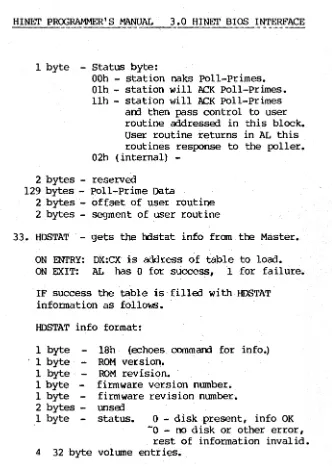
44. NEThdstat (NET HARD DISK STATUS) -- gets Network Hard Disk status.
ON ENTRY -- Register Be has address of block to load NET hdstat information.
HDSTAT info format:
1 byte - l8h (echoes command for info) 1 byte - ROM version.
1 byte ROM revision.
1 byte - firmware version number. 1 byte - firmware revision number. 2 bytes - unused
1 byte - status.
o -
disk present, info OK. -0 - no disk or other error,rest of information invalid. volume entries.
4 32 byte
Format of Volume Entry
-1 byte - status. OFFh - volume present.
1 byte 1 byte 1 byte 1 byte 2 bytes 2 bytes 2 bytes 1 byte
o -
volume not present. - current track for volume.- number of tracks on volume. - sectors per track.
- head mask.
- location of partition offset table. - location of bad sector table.
- location of bad sector dirty flag. - error in volume open durirg firmware
initialization (0 = no error) • 10 bytes - Volume Label.
10 bytes - unused
HINET PROGRAMMER'S MANUAL 3.0 HINEr BtOS INTE~'ACE
45. SetNetMode (SET NETWORK MODE) -- this call allows multi-user application programs to set
the local lK Network Buffer mode to one of three states to ensure current data at all times. See Section 6 for more information. The three available states are:
0) Always use the lk Network Buffer. This is the default mode; it is automati-cally selected after a cold or warm boot.
1) 00 not use the buffer contents on the next Net Read request - force a network transmission to ensure current data. This will replace the lk network buffer contents; all subsequent NetReads will use the buffer contents.
2) 00 not use the buffer contents until a cold or warm boot or until the program changes the network buffer usage mode.
ON ENTRY -- C = New Mode (0, 1, 2)
ON EXIT -- A = Old Mode
REGISTERS DESTROYFD -- HL
46. SetListType -- the sequence for accessing the printer attached to the console.
ON ENTRY -- H
=
first character of enable sequence.Release: 12/1/84
L
=
second character of enable sequence.HINET PROGRAMMER'S MANUAL 3.0 HINET BIOS INTERFACE
D = first character of disable sequence.
E = second character of disable sequence.
ON EXIT -- None.
REGISTERS DESTROYED -- None.
47. INITHARD (HARD DISK RESET) -- resets either the local or Network Hard Disk. Reset Network Hard Disk works only fram the Master.
ON ENTRY -- C = 0, reset Network Hard Disk.
= 1, reset local Hard Disk.
ON EXIT -- Hard Disk reset.
HINET PROGRAMMER'S MANUAL 3.0 HINET BIOS INTERFACE
48. MakeMcdeRequest (WRITE MODE REQUEST)
--ON ENTRY -- HL - address of entry block. DE - address of exit block.
ON EXIT -- data is in exit block.
Entry Block: Exit Block:
Request Type Reponse Status
Vollnle # Unit Status
unit # 8 byte Name
Value # field
User #
Drive # (logical)
REGISTERS DESTROYED -- None.
49. DESCRIBE (BIOS INFORMATION)
ON ENTRY -- None.
ON EXIT -- HL has address of table.
REGISTERS DESTROYED -- None.
DESCRIBE Table:
HINET PROGRAMMER'S MANUAL 3.0 HINET BIOS INTERFACE
Product type
Operating system type Version #
Revision #
Patch Mod
4 bytes, PROM Serial Number
6 bytes, option map
1 byte password
2 bytes, DMA Vector address 2 bytes, Lock byte
2 bytes, Lock DMA
3.1.3 BIOS CALLS THROUGH INTERRUPT 78
DMS has implemented Interrupt 78 as a COMMON BIOS entry point. The user loads the registers required by the specific BIOS call, moves the COMMON BIOS function number to the AH register arrl then issues an INT 78. This method may also be used by CP/M-86 programs; however,
the "COMMON' Function Number--not the CP/M-86 Function Number--must be used.
The SI, BP arrl DS registers are saved. All others (inclwiDj the flags) may be modified by the BIOS. The stack is manipulated to ensure the flags, as modified by the BIOS, are returned to the user.
3.1.4 CP/M-86 BDOS CALL 50 -- CALL THE BIOS
CP/M-HINET PROORAMMER' S MANUAL 3.0 HINET BIOS INTERFACE
86 operatiI'J) System Manuals. When usiI'J) BOOS
Call 50, only the function number,
ex
and OXregisters may be passed to the BIOS. See below for more information.
3.1.5 CP/K-86 and KS-DOS BIOS CALLS
For compatibility, the parameter block passed by the application is the same for CP/M-86 and MS-OOS. It is 5 bytes in length and contains:
BYTE
o
BIOS function Number1-2 value to be loaded into cx
3-4 value to be loaded into
ox
If the function requires more data than can be passed- in
ex
amox,
OX:CX will be thesegment:offset of a parameter block tailored for the function being called. For example - the parameter block used by SNDNET am RCVNET is:
BYTE
o
User number1-2 offset of data to sem/receive 3-4 segment of data to sem/receive 5-6 length of data to sem/receive
The following pages in this section show the currently implemented BIOS calls available in all three operating systems. The Z-80 am the Z8l6 share the same function number; however they may not al ways expect the same parameters or work exactly the same way. See the section on the particular function desired for specific
HINET PROGRAMMER'S MANUAL 3.0 HINET BIOS INTERFACE
infonnation. CP/M-86 uses the function numbers in the CPM-86 column when making BIOS calls via
BOOS Call 50.
If using INT 78, the function numbers in the COMMON column of the BIOS Call Table should be used. MS-DOS uses the function numbers from the COMMON column for both the DMSBIOS am the INT 78 methods of accessing the BIOS. THE INT 78 METHOO IS PREFERRED.
3.2 MACHINE BIOS CALLS FOR 8086/88 DEVICES
This section describes the calls that can be made to the MACHINE BIOS (formerly callerl the
Gt1I' BIOS) on DMS 8086 am 8088 baserl machines. MACHINE BIOS calls are specific to the worksta-tions (CPUs) while the SYSTEM BIOS calls are available through every type of station. The SYSTEM BIOS for CP/M-80 (on 816s), CP/M-86 am MS-DOS all use some of these call s. They can be callerl by a user through two methods:
A. USING INTERRUPTS TO CALL MACHINE BIOS FUNCTIONS:
For all functions under MS-DOS am CP/M-86 except video functions:
Put function number in AH,
load all registers as Function you are calling expects them,
HINET PRQGRAHMER'S MANUAL 3.0 HINET BIOS INTERFACE
For example, to call MACHINE BIOS function 33 HDSTAT:
mov ah,33
mov cx,offset HDBUFFER mov dx,ds
int 78
B. DIRECT BIOS CALL through BOOS.
Under CP/M-86, BOOS call 50 calls the BIOS which can then call the MACHINE BIOS. To make the call you must set up two buffers: one for the BOOS to use to call the BIOS, and one for the BIOS to use to call the MACHINE BIOS.
Here is an example:
To call MACHINE BIOS function 33 HDSTAT.
HDSTAT expects DX and
ex
to hold the address of the buffer to read information into. Say the buffer is locatErl at address DATASEG:HDBUFFER. Set up a buffer for call to HDSTAT from the BIOS callErl BIOScall (inDATASEG segment). This buffer contains DATASEQ equ 1000h (segment this program is runnirg in).1 byte - MACHINE BIOS FUNCTION NUMBER (in this case 33 (HDSTAT Call»
1 word - VALUE to load into
ex
for MACHINE BIOS call (in this case offset of HDBUFFER) •HINET PR~RAMMER' S MANUAL 3.0 HINET BIOS INTERFACE
1 word - VALUE to load into OX for MACHINE BIOS call (in this case value of DATASEG) •
In code:
BIOScall db dw dw
33 HDBUFFER DATASEG
Now set up a buffer (BDOScall) for BDOS to call BIOS with:
1 byte - BIOS FUNCTION NUMBER
(always 40 (28h) - for Call to Machine) • 1 word - VALUE to load into
ex
for BIOS call(in this case offset of BIOScall) • 1 word - VALUE to load into DX for MACHINE
BIOS call (in this case value of DATASEG) •
In code: db dw dw
28h BIOScall DATASEG
Now to call the Machine function we do this: (assuming DS already has value OATASEG in it.) mov dx,offset BDOSca11
mov cx,50
HINET PROGRAMMER'S MANUAL 3.0 HINET BIOS INTERFACE
INDEX OF 8086/88 MACHINE BIOS FUNCTION NUMBERS
Function INT 78 Function INT 78
auxF1ush 7 MErliaSame 13
auxlnit 43 net InfoReq 45
auxlnput 8 partAddr 44
auxoutput 9 printScreen 40
auxstatus 6 prnOutput 5
auxStatl 17 prnStatus 4
C1rLock 16 OCVNET 38
clrpol 36 SETERR 24
COERCE 31 SETIOBF 20
con Input 2 setIOptr 15
conOutput 3 setpol 35
conStatus 0 SETPPA 32
conF1ush 1 setPResc 46
DIRNET 28 SETTRY 26
diskRead 10 SNDNET 37
disk Write 11 spool Flush 14
DMSinfo 41 spool Mess 47
GETASS 22 TIMDAT 34
GETERR 25 UNLOCK 30
GETIOBF 19 VIDEO 39
getMemSize 12 WHO 27
HDSTAT 33 WRScommand 42
LOCK 29
MAKASS 21
3.2.1 8086/88 MACHINE BIOS FUNCTIONS
The 8086/88 MACHINE BIOS functions are
1 istErl below in numer ic order. The function number must be placed in register AH before Interrupt 78 or BOOS call 50 are invokErl.
HINET PROGRAMMER'S MANUAL 3.0 HINET BIOS INTERFACE
The following numbers are for the INTERRUPT 78
method of call ing the BIOS.
o.
CONSTATUS - get status of console input.ON ENTRY: nothing.
ON EXIT: If there is a char the zero flag is reset and char is in AX. Otherwise zero flag is set, 0 in AL.
1. CONFLUSH - empty the keyboard type-ahead buffer and input port. This routine keeps getting characters and throwing them away until there are no more.
2. CONINPUT - get character from console.
ON EXIT: AX hold char. Routine does not return until it has a character.
3. CONOUTPUT - Outputs a character to the console. ON ENTRY: Char is in AL.
ON EXIT: nothing.
4. PRNSTATUS - check printer status.
ON EXIT:
For all devices except spooler: Zero flag reset if printer is ready.
HINET PROGRAMMER'S MANUAL 3.0 HINET BIOS INTERFACE
a spool block. Status is baserl on the results of this attempt.
Urner MS-DOS a timirg loop prevents the operating system from prematurely aborting the print routine if the printer signals it is not ready (e.g., its buffer is full).
If ready: zero flag reset, AL has FF
If not ready: zero flag set, AL has 0
5. PRNOUTPUT - output a char to the list device.
ON ENrRY: char is in AL.
ON EXIT:
IF SPOOLER
char is in AL
success - zero flag reset. failure - zero flag set.
6. AUXSTATUS - get status from the auxiliary output dev ice.
ON EXIT: AL contains status from Read Reg Oof . S10 Zero flag is reset if device is teady to
transmit.
7. AUXFLUSH - empty the auxiliary buffer, if
any. (1«71' IMJ.ILIIMDI'l"ID as of 9/1).
8. AUX1NPUT - get character from auxiliary device.
ON EXIT: char is in AL.
HINET PROGRAMMER'S MANUAL 3.0 HINET BIOS INTERFACE
9. AUXOUTPUT - write character to AUX device.
ON ENTRY: char is in AL. ON EXIT: nothing
10. DISKREAO - read from disk.
ON ENTRY: AL - log ical dd ve number ES - buffer segment
01 - buffer offset
ox - sector
BX - track
ex - number of l28b sectors to read
ON EXIT: Info is read into the buffer at ES:OI. If success zero flag is reset else zero is set and CL has number of sectors successfully read.
11. OISKWRITE - parameters identical to disk read. (see above)
12. GETMEMSIZE - returns the physical size of manory.
ON EXIT: ex has memory size in (16 byte) paragraphs. (E.g., 1000H
=
64K manory.)13. MEDIASAME - returns the current value of the moo ia change flag, and resets the med ia change
HINET PROGRAMMER'S MANUAL 3.0 HINET BIOS INTERFACE
there is an assign to make MS-DOS keep up with the latest.
14. SPOOLFLUSH - Ends a spool job if one is active.
15. SETIOPTR - relocates the iobyte to the address asked for.
ON ENTRY:
ex
has offset of address. DX has segment of address.If addr is 0:0 it means reset to default IOBYTE address.
ON EXIT: moves the current IOBYTE to this address, and thereafter accesses that address when it needs IOBYTE.
16. CLRrOCK - sends byte to Master that says clear all locks for our user number.
ON ENTRY: nothing
ON EXIT: AX is 0, zero flag set.
17. AUXSTATUS1 - Get status of aux device from SIO read reg 1. This call is needed only by the
ROM BIOS Bmu1ation.
19. GETIOBF -Get the IOBYTE. ON EXIT: AL has the IOBYTE.
HINET PROGRAMMER'S MANUAL 3.0 HINET BIOS INTERFACE
20. SETIOBF - Set the IOBYTE.
ON ENTRY: value to set IOBYTE is in CL.
21. MAKASS - This call attempts to assign a partition to a logical drive number. The only valid drive types are HiNet and Memory disk.
(IMPORTANT: BIOS Memory disk assignments are only valid on CP/M-86. MS-DOS does not allow BIOS manipulation of the Memory Allocation Table. An attempt to assign a Memory Disk while running unler DOS will resul t in a crash. However DOS Merriory Disks are available through the MS-DOS CONFIG.SYS device drivers.)
The format of the assign request-buffer is:
byte:
o
-
logical drive number 1-8 - partition name(set by caller) (set by caller) 9 - partition size
10 - partition number
11 - control byte (caller sets OS type) 12 - volume number
13 - drive type (set by caller) 14 - write status
15-20 - password (set by caller)
OS type set by caller in control byte: Low bi t
determ ines OS. See DIRNET for si ze and layout of the Control byte.
CP/M-80, HIDOS, & CP/M-86 - 0
HINET PROGRAMMER'S MANUAL 3.0 HINET BIOS INTERFACE
The possible drive type values are listed here. only the first two are currently valid for the 86 stations. The rest are found in use with Z-80 stations:
Network Partition 60h
Memory Disk EOh
8 inch Hard Disk 40h 5 inch Hard Disk COh mini-floppy(one side) - BOh mini-floppy(double side) AOh 8" floppy (single dn) - 20h 8" floppy (double dn) - OOh
ON ENTRY: CX has offset of request buffer DX has segment of request buffer
ON EXIT:
IF SUCCESS
AL
=
0 and all bytes in buffer not set by caller are filled in by bios. Note that the write status field is set on the basis of the control byte, so if its an ownable partition it is marked as unowned. NO query about its present status is made by this module.IF FAIL
AL = 1 assignment invalid.
AL
=
2 invalid partition name or passwordAL = 3 insufficient memory for memdisk.
AL = 4 man disk already in use.
AL = 6 parti tion is not of requested OS type.
NOTE: even if an assign fails, the ownership of the previously assigned partition on that logical drive is released.
HINET PROGRAMMER'S MANUAL 3.0 HINET BIOS INTERFACE
22. GETASS: Get information about the parti tion currently assigned to a logical drive.
Format of buffer:
BYTE
o
logical drive number (set by caller)1-8 partition name
9 partition size
10 partition number
11 control byte
12 voltnne number
13 drive type
14 write status
15 unused
16 unused
ON ENTRY: DX:CX is address of buffer.
ON EXIT:
IF SUCCESS, Buffer is filled out with all current info. AL = 0
IF FAILURE, AL = 5 meaning drive number in request was illegal.
NOTE: A parti tion ntnnber of OFFh means dr i ve is unassigned.
ON PARTITION WRITE OWNERSHIP:
Whenever a Network partition is assigned, the control byte is checked. If the control byte
indicates a write status of RlW, RIO or HlooS, the write status is set to that value. Otherwise the write status is set to unknown. Whenever a memory disk is assigned, its write status byte
HINET PROGRAMMER'S MANUAL 3.0 HINET BIOS INTERFACE
On OS initialization, i f any of user's default partition names have the high bit set on the
first character, the OS attempts to gain ownership status for that drive through a Network ownership request. If ownership is denied, a message is given to user warning them
that they cannot write to that drive.
Whenever a write is attempted, the write status of the drive is checked. If it is not equal to the user number or read/write status or shared (when running HIDOS), the user is informed that he or she can't write to that partition, and a failure is returned. CP/M then warm boots, while MS-DOS will query what the user wants. No
matter what the user says, he or she cannot write to the partition without an abort and an explicit write ownership request through ASSIGN.
Whenever an owned drive is re-assigned, owner-ship is automatically released by MAKASS. If the assign fails, the status of the drive remains unowned unless the assigning applica-tion makes a new explicit ownership request.
24. SETERR ~ turns on and off the display of error messages when there is a net error. Sets variable ERRFLG. oefault setting is
o.
ON ENRTY: CL has value to load ERRFLG with.
o -
error messages off-0 - error messages on ON EXIT: ERRFLG is set.
HINET PROGRAMMER'S MANUAL 3.0 HINET BIOS INTERFACE
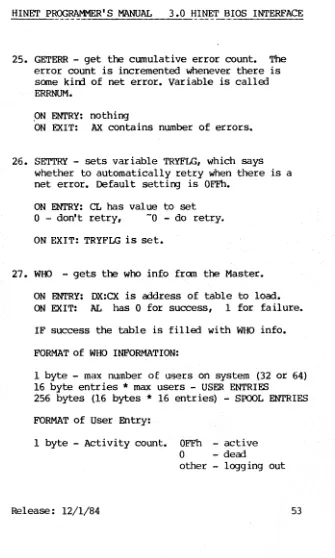
25. GETERR - get the cumulative error count. The error count is incremented whenever there is some kind of net error. Variable is called ERRNUM.
,ON ENTRY: nothing
ON EXIT: AX contains number of errors.
26. SETTRY - sets variable TRYFLG, which says whether to automatically retry when there is a net error. Default setting is OFFh.
ON ENTRY: CL has value to set
o -
don't retry, -0 - do retry.ON EXIT: TRYFLG is set.
27. WHO - gets the who info from the Master.
ON ENTRY: DX:CX is address of table to load. ON EXIT: AL has 0 for success, 1 for failure.
IF success the table is filled with WHO info.
FORMAT of WHO INFORMATION:
1 byte - max number of users on system (32 or 64) 16 byte entries
*
max users - USER ENTRIES256 bytes (16 bytes
*
16 entries) - SPOOL ENTRIESFORMAT of User Entry:
1 byte - Activity count. OFFh - active
o
-
dead [image:58.398.43.378.45.603.2]HINET PROGRAMMER'S MANUAL 3.0 HINET BIOS INTERFACE
8 bytes - User Name.
3 bytes - login time (secs,mins,hours)
3 bytes - last request time (secs,mins,hours) 1 byte - last request command byte.
FORMAT of Spool Entry
1 byte - spool status 0 - starting spool 1 - spooling· 2 - ready to print 3 - printing 4 - stop print 5 - waiting
OE5h - aborted or done
1 byte - user number of User spooling. 1 byte - spool ID (top nibble job #,
low nibble block #). 2 bytes - time job started (min,hour). 2 bytes - track # of last sector of job. 1 byte - sector # of last sector of job. 8 bytes - spooler's name.
28. DIRNET - gets DIRNET info fram Master (reads ALLOC Table) ;
ON ENTRY: DX:CX has address of table to fill out. First byte is the volume number (0,1,2,3) of the Hard Disk to read.
ON EXIT: AL has 1 for failure, 0 for success.
On success table is filled with a table with 64 entries. Total size
=
lK.FORMAT of DIRNET INFORMATION: (same as ALLOC Table)
HINET PROGRAMMER'S MANUAL 3.0 HINET BIOS INTERFACE
1 byte - size (0 - end of table,l - 256k, 2 - 512K, 3 - IMEG, 4 - 2MEG, 5 - 4MEG etc. up to 32MEG). 8 bytes - Partition name.
6 bytes - Reserved 1 bytes - Control byte.
FORMAT OF CONTROL BYTE
-BIT 7 6 5 4 3 2
I
1
I o I
/-->
OPERATING SYSTEM 000 - CP/M-80--> NOT USED 001 - MS-DOS 010 - CP/M-86
\---->
--->
WRITE TYPE OF PARTITION00 - read/write 01 - read onl y 10 - ownable 11 - reserved
1 - shared partition (HIDOS)
o - not shared. ---> 1 - automatic tape backup
o - no auto tape backup
29. LOCK - used for adding strings to the Masters lock table.