DESIGN OF SINGLE FEED CIRCULARLY POLARIZED
HARMONIC SUPPRESSED MICRO STRIP PATCH ANTENNA
FOR X-BAND APPLICATIONS
1P.POORNA PRIYA,2HABIBULLA KHAN,3CH.ANUSHA,3G.SAI TEJASWI,
3CH.SIVA RAMA KRISHNA
1Asstt Prof.,department of ECE, DST-FIST SPONSORED DEPARTMENT, K L University, Vaddeswaram. 2Dean student affairs, department of ECE, DST-FIST SPONSORED DEPARTMENT, K L University, Vaddeswaram. 3Students, department of ECE, DST-FIST SPONSORED DEPARTMENT, K L University, Vaddeswaram.
E-mail: 1[email protected],2[email protected],3[email protected], 3[email protected],3[email protected].
ABSTRACT
Introduction of a symmetrical slot near feed point for a symmetrical radiation patch of micro strip patch antenna realize both circular polarization and higher order mode suppression. Simulated and experimental results shows that application of symmetrical slot near feed point for asymmetrical patch can remarkably suppress the harmonic frequencies. Measured return loss and VSWR results shows that the proposed antenna suppress the higher order harmonics by maintaining circular polarization in X-band applications. Keywords: Circular Polarization, Harmonics Suppression, Micro Strip Antennas, Antenna Radiation
Patterns
1. INTRODUCTION
X-band frequencies are used for communication applications in recent days. A low profile, light weight micro strip patch antenna can be designed mainly for radar, navigation and satellite communication. The Circular polarized micro strip patch antenna has the advantages of greater flexibility in orientation angle between transmitters and receivers compared to the linear polarization, better mobility and reduction in multipath reflections than linear polarized micro strip patch antenna. These antennas are widely used in X-band applications.
The nonlinear micro wave devices will act as front ends of wireless systems which produce harmonic frequencies will transmitted through antenna lacks an ability of harmonic suppressions results interferences with other wireless systems. The polarization of any field can be represented by a set of two orthogonal linearly polarized fields. Then these polarized fields along x-axis and y-axis is sufficient to represent any TEMZ fields is given by.
E=E (x± jy)
Fig 1 Side View And Top View Of Proposed Antenna
2. ANTENNA DESIGN
In this method, antenna is modeled as multiport network. This planar model is treated as a loss less resonator during analysis. The total periphery of antenna model divided into several sections of small widths and each of these sections are considered as a port. The entire radiation resistance network is treated as one multi port network ‘β’ as shown below and equivalent ‘LC’ equivalent is given below
= --- (1)
Where, p = un-connected ports of the various segments of γ
C and d = represents inter connected ports.
Zr= Zpp+ ( Zpc– Zpd) 1/Zep ---( 2 )
The electric current Ip fed into the pth port, the
voltages at the inter connected ‘c’ and‘d’ ports are given by,
Vc= Vd= [ Zcp+ [Zcc– Zcd] Zcp] * Ip--- ( 3 )
The reactance’s of proposed antenna for inter connected ports and the combined reactance’s of inter connected and unconnected ports are replaced with inductors and capacitors ( C1, C2) in which
the inductance I1 corresponds to transverse and
longitudinal narrow strips. Capacitance C1 is
capacitance triangular patch and C2 is gap
[image:2.612.95.581.72.218.2]capacitance between triangular patch and the radiation patch and structure is shown in fig (2)
Fig 2 Reactance’s Of Proposed Antenna And Equivalent Circuit
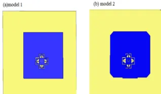
[image:2.612.352.511.380.473.2]The fig.3 shows the design of with and without truncation circularly polarized micro strip patch antenna with meandered slot the dimensions of the designed model are presented in table 1&2 .The coaxial feeding is used in this model with 50ohms impedance at feed point the antenna is prototyped on RT Duroid substrate with dielectric constant 2.33 and thickness h= 1.6 mm. the operating fundamental frequency is 1.5 GHz.
Fig 3 Model 1-Without Truncation And Model 2- With Truncation
The detailed dimensions of the without truncated radiating patch feed location is tabulated in table 1 for model 1
Table 1 Proposed Antenna Without Truncation
GL PL Fy W1 W2 W3 W4
100
mm 53.8mm 18.9mm 8mm 6.8mm 0.4mm 3.1mm
W5 W6 L1 L2 D1 CL Cw
5.8
mm 0.6mm 4.6mm 4.6mm 1mm 20mm 1mm
Table 2 Proposed Antenna With Truncation
G
L PL Fy W1 W2 W3 W4 Qj
10 0 m m
53.8
mm 18.9mm 8mm 6.8mm 0.4mm 3.1mm 4.5 m m W
5 W6 L1 L2 d1 CL Cw
5. 8 m m
0.6
mm 4.6mm 4.6mm 1mm 20mm 1mm
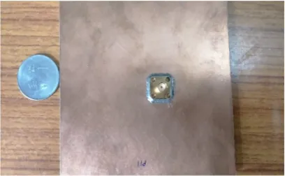
[image:3.612.314.532.204.291.2]The proposed antenna is simulated for two different substrates duroid using ANSYS HFSS simulation software and is characterization is optimized. The fabricated antenna design is shown in fig (4.a, 4.b)
[image:3.612.93.297.360.486.2]Fig-4.A Back View Of Fabricated Antenna
Fig-4.B Front View Of Fabricated Antenna
3. RESULTS AND DISCUSSION:
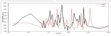
The proposed antenna is designed and simulated using ANSYS HFSS tool the simulated results like return loss, vswr, gain, radiation pattern and axial ratio are analyzed and presented in this work. Return loss characteristics of with and without truncated Antenna are combined and shown in fig 5.a.
Fig.5.A Return Loss Characteristics For Model 1 And Model 2
In the model 1 the 2nd harmonics are observed at
frequency 10.5GHz so to suppress the harmonics, the proposed antenna has been changed to model 2. In model2 truncated antenna suppers the 2nd
harmonic and the band width of the antenna is increased (7.1GHz to 9.2GHz.)
[image:3.612.314.531.463.533.2]Fabricated proposed antenna for model 2 measured Return loss shows that the antenna is converged at 9.2GHz with -25db return loss is shown in fig 5.b
Fig 5.B Measured Return Loss For Model 2
[image:3.612.95.299.526.651.2] [image:3.612.314.530.613.696.2]9.2GHz .the simulated and measured results are matched. The measured VSWR for converged frequency is 1.4.
Fig 6.B Measured VSWR For Fabricated Antenna
Simulated radiation characteristics of both models in both E and H planes are shown in fig7.a and 7.b
Fig 7.A Simulated Radiation Pattern For Model 1at Theta And Phi
Fig 7.B Simulated Radiation Pattern For Model 2at Theta And Phi
Fig 8 Simulated Results Of Gain
[image:4.612.97.522.66.202.2]Fig 9 shows the surface current distribution with maximum gain of 3.5dB
[image:4.612.313.529.263.333.2]Fig 9 Simulated Current Distribution Results In E-Plane
[image:4.612.97.301.286.356.2]Fig 10 shows the result of axial ratio at converged frequencies for with and without truncated antenna and it gives good compromise between liner polarization and circular polarization
Fig 10 Simulated Axial Ratio For Model 1 And Model 2
4. CONCLUSION
Single fed circularly polarized micro strip patch antenna for harmonic suppression is proposed this antenna is etched on RT-Duroid(relative permittivity 2.2) with truncated corners, operates at 1.5GHz.The higher order harmonics are suppressed by placing slots at the feed point. Simulated and particles results has good compromise for vswr, gain, antenna efficiency, radiation pattern and axial ratio.
REFRENCES:
[1] Y. L.Kuoand K.L.Wong, “A circularly polarized micro strip antenna with a photonic band gap ground plane,
“inProc.APMC, Taipei, Taiwan, 2001,
pp.647–650.
[2] Swoon, B.M.Lee, Y.J.Yoon, W.Y.Song, and.-G.Yook, “A harmonic suppression antenna for an active integrated antenna,” IEEE
Microw.WirelessCompon.Lett., vol.13,
no.2, pp.54–56, Feb.2003.
[3] X.-C.LinandL.-T.Wang, “A broadband CPW-fed loop slot antenna with harmonic control,”IEEE Antennas Wireless
Propag.Lett., vol.2, pp.323–325, 2003.
[4] Y.J.Sungand Y.S.Kim, “An improved design of micro strip patch antenna susingphotonic band gap structure,” IEEE Trans.Antennas
Propag., vol.53, no. 5, pp. 1799–1804,
[5] S.Lin, K.Huang, andJ.S.Chen, “Harmonic control for an integrated micro strip antenna with loaded transmission line,”Microw.Opt. Technol.Lett., vol.44, pp.379–383, 2005
[6] L. Inclan-Sanchez, J.-L.Vázquez-Roy, andE.Rajo-Iglesias, “Proximity coupled micro strip patch antenna with reduced harmonic radiation,” IEEETrans.
AntennasPropag., vol.57, no. 1, pp. 27–32,
Jan 2009.
[7] C. Jiang, X.-X.Yang, andQ.-L.Bai, “Harmonics suppression of circularly polarized micro strip antenna by defected ground structure,” (in Chinese)
RadioCommun.Technol. vol.36, no.3,
pp.24–27, 2010.
[8] D.Zhou, R.A.Abd- Alhameed,
C.H.See,M.S.Bin Melha,Z.B.Zainal-Abdin, and P.S.Excel,“New antenna designs for wideband harmonic suppression using adaptive surface meshing and genetic algorithms,”Microw.AntennasPropag.,vol.5, no.9,pp.1054–1061,2011.
[9] P.PoornaPriya and Dr.Habibulla khan,” Gain Enhancement of V-slotted Triangular shape micro strip patch antenna for WIMAX application” IJERAvol.2, pp.1187-1193, 2012.
[10] Yunxue Xu, Shuxi Gong, and Tao Hong “Circularly Polarized Slot Microstrip Antenna for HarmonicSuppression” IEEEANTENNASANDWIRELESSPROPA GATIONLETTERS,VOL.12,2013