http://dx.doi.org/10.4236/jcc.2015.37003
Management of Intelligent Campus Wireless
Sensor Networks Based on Runtime Model
Ping Zhang, Jianzhong Wang
College of Fundamental Education, Sichuan Normal University, Chengdu, China Email: [email protected]
Received 11 June 2015; accepted 12 July 2015; published 17 July 2015
Copyright © 2015 by authors and Scientific Research Publishing Inc.
This work is licensed under the Creative Commons Attribution International License (CC BY). http://creativecommons.org/licenses/by/4.0/
Abstract
To quick customize and develop intelligent campus internet of things (ICIOT) system more effi-ciently, in this paper an approach based on runtime model to managing intelligent campus wire-less sensor networks is proposed. Firstly, manageability of intelligent campus wirewire-less sensors is abstracted as runtime models which automatically and immediately propagate any observable runtime changes of target resources to corresponding architecture models. Then, a composite model of intelligent campus wireless sensors is constructed through merging their runtime mod-els in order to manage different kinds of devices in a unified way. Finally, a customized model is constructed according to the personalized management requirement and the synchronization between the customized model and the composite model is ensured through model transforma-tion. Thus, all the management tasks can be carried through executing operating programs on the customized model. In the part of the teaching area schools conducted experiments and compared with the traditional method, this method can be more effective management of campus facilities, more energy efficient and orderly, which can reach a 16.7% energy saving.
Keywords
Wireless Sensor Networks, Intelligent Campus, Runtime Model, Intelligent Campus Internet of Things, Software Architecture
1. Introduction
things. It is through the spread of all kinds of information on campus sensing equipment, gathering campus classroom, office, laboratory and the library environment such as light, electricity, temperature switch, all kinds of equipment, personnel location information and connect to the school LAN, to realize intelligent identification, location, tracking and monitoring, analysis and management, which can automatically manage the light, fan or air conditioning equipment and personnel. In intelligent campus Internet of things there are different types of application scenarios, sensing devices in different application scenarios corresponding to different objective things, so the connection between objective things in the scene and the sensor device needs to be established implementing the corresponding mapping relationship, even in the same application scenario, elements such as the management needs, the deployment environment, the sensing equipment, etc. may also change during the long time running. So the management services in the intelligent campus Internet of things on demand to the campus information management has brought certain difficulty. The core of Intelligent campus is the Internet of wireless sensor network, various types of sensors providing data read in different ways, and at the same time, data from the sensing device is real-time with a large amount of data, a certain attribute of the specific device to the mapping of data, and you need to write a lot of conversion code [1], which brings the greater complexity to the access of the information. In order to be able to quickly customize, develop and extend intelligent campus Internet system, according to the requirements of management, improve the versatility and extensibility of intel-ligent campus Internet system, and reduce the complexity of the development, in this paper the runtime software architecture model will be introduced to intelligent wireless sensor network classroom management process and a runtime model based intelligent campus wireless sensor network management method will be put forward. First, we construct a campus runtime model, through the model structure, model synchronization and model transformation to implement sensors to collect data to the objective things in intelligent campus application sce-nario for the attributes of the object mapping, thus enabling the administrator to orient application scesce-narios of intelligent campus network system with rapid customization, development and extension.
The second section of this paper outlines the overall framework of the intelligent campus wireless sensor network management method based on the runtime model. In the third section, the construction method of the runtime model of the sensing device of the intelligent campus wireless sensor network is introduced. The fourth section describes the method of extracting and merging the running time model and the method of data synchro-nization. In the fifth section, the paper introduces the method of the combination model to the application scene model. The sixth section describes the experimental research and compares the traditional method with the me-thod proposed in the paper. The seventh section summarizes the full text.
2. Management Method of Intelligent Campus Wireless Sensor Network
Based on the Runtime Model
coupling application system with the underlying node [7]. And some work [8]-[10] on the application of wire-less sensor net system modeling method, the work will apply model method to the demand of application de-velopment phase and design phase, effectively improving the level of abstraction of Internet programming. However, IOT systems need to be able to adapt to the demand, the environment and its own change in the process of long running, while the traditional model methods can’t modify and debug management logic in the running process of the system.
Model in software engineering is the carrier between ideal software and management knowledge. The runtime software architecture model represents the overall architecture of the system with a set of manageable unit, and through runtime information display like internal structure, status, configuration hidden in the system to be de-scribed as a standard, management perspective oriented structural view, it can effectively improve the level of abstraction and automation degree the development of IOT systems [11]. The runtime software architecture model has won the wide attention in academia and industry. A lot of research work has proved the important role of it in a different system and management mode [12]. The runtime model is now widely used in different systems to support management function such as the system self-healing [13], management functions and dy-namic adaptive [14] and also used in some of the sensor network management [15].
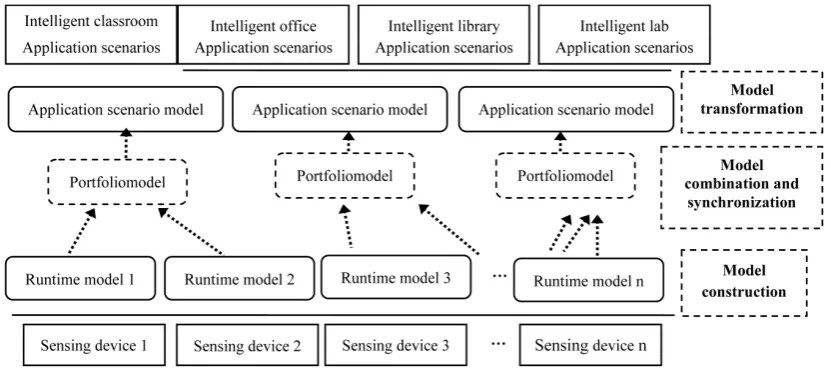
In order to be able to quickly customize, develop and extend intelligent campus network system according to the requirements of management, in this paper a model based on runtime intelligent campus wireless sensor network management method is proposed. This method is that during the process of the runtime software archi-tecture model introduced into the intelligent campus wireless sensor network management, firstly campus run-time model is constructed, through the model structure, model synchronization and transformation to improve the versatility and extensibility of intelligent campus Internet system, reducing the complexity of the develop-ment, specific methods summary as shown in Figure 1.
[image:3.595.106.522.521.707.2]This method first constructs runtime model structure for different sensing equipment of intelligent campus, and based on the interface of equipment management in the model layer monitoring different sensing equipment is realized, the data synchronization between runtime model and gathering information maintained. Secondly based on the runtime model the data collected by different sensing devices of intelligent campus is combined, (including model extraction and merging), realizing the unified management for different sensing equipment by combining the models of the scene; Finally the connection between the object of objective things and sensing devices in different application scenarios of intelligent campus such as, intelligent classrooms, intelligent office, intelligent laboratory library is established, realizing the mapping from a portfolio model to different application scenario models by transformation, which makes all kinds of data collected by intelligent campus sensing device performed in the form of various attributes of the objects in the objective world. The method is based on the ex-isting management interface to construct the runtime model of sensing equipment, shielding isomerism of sens-ing device management interface, reducsens-ing complexity; Based on distributed senssens-ing device runtime model the combination model is constructed, blocking the distribution of the sensing device. Through model transforma-tion the mapping from a portfolio model to the applicatransforma-tion scenario model is implemented. With the methods
above, all kinds of data collected by sensing equipment can be expressed in the form of things object properties in the objective world, thus the administrator can rapidly customize, develop and extend intelligent campus network system facing application scenarios.
3. Intelligent Campus Wireless Sensor Network Model Construction
Method Based on the Runtime Model
Intelligent campus wireless sensor network is mainly to solve the information perception problems of all kinds of sensing equipment in CIOT, but it is of great difficulty and complexity to obtain information because of the diversity and heterogeneity of sensing equipment. Based on the basis of reference literature [16] [17], with the tools of SM@RT [18] [19] sensing equipment runtime model is constructed, the information acquired and processed in a unified way. SM@RT is a runtime software construction methods and tools driven by model proposed by the research team, including specific areas SM@RT language modeling language and SM@RT code generator. SM@RT language code generator allows the users to define the runtime software architecture of meta-model and access model. Meta model defines the structure and manageable elements of the target system, and access model states the way of management of these elements in meta-model, that is, API.SM@RT genera-tor of the target system is called, with meta-model and access model as input, the infrastructure maintaining run-time software architecture can be automatically generated, and then the underlying system of real-run-time state model is reflected in the runtime model. SM@RT source code can be downloaded from literature [20].
4. Intelligent Campus Wireless Sensor Network Model Combination
Method Based on the Runtime Model
Intelligent campus wireless sensor network consists of many different types of sensors, the application systems like intelligent classrooms, campus intelligent office, intelligence laboratory, and the intelligent library need the unified analysis and processing of the data collected by different sensing device according to management goals. Intelligent classroom system requires monitoring and management for all the classroom lighting equipment, sensors, temperature sensors and brightness, the location of the projector, computer multimedia classroom sys-tem of sensors in school. Intelligent office syssys-tems requires analysis and processing of lighting equipment, brightness perception, temperature sensing equipment and office staff position in all office area of the school. Intelligent library system need analysis, processing and monitoring for the lighting equipment, brightness per-ception devices, temperature, humidity sensors and books location in all the school library. These sensors need unified management, in order to realize the different types of complex management tasks. In this article the me-thod of combination is adopted on the basis of sensing device model in operation, reorganization and merger in the form of a portfolio model, to realize the unified management of different types of sensors, including model extraction and merging, and data synchronization.
4.1. Extract and Merge Models
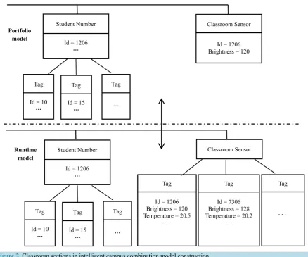
Figure 2. Classroom sections in intelligent campus combination model construction.
Model pieces of combination needs to be able to obtain the information collected by the target device from a specific sensing device in the runtime model. Sensing equipment run time model and the model fragments cus-tomized by administrators are stored in the form of an XML file, each element in the model has one and only one path from the root node which can navigate to the element. Model fragments of combination model from different sensor runtime models of intelligent campus application scenario. They have not grammatical relation and can merge the root node of the each model piece as direct child nodes of the root nodes from combination model to. At the same time for element naming conflicts of each model fragment, a namespace needs maintain-ing, to replace and record conflict element naming (seeFigure 3).
4.2. Data Synchronization
On the basis of the combination model, the unity of the combination model of multiple systems management can be achieved only by maintaining the data synchronization between the combination model and the system run-ning model. Portfolio model is composed of different system runtime model elements, whose data consistency is completed by the different model fragments. In the runtime system model, a copy of model fragment is deployed, and with the change of the model by polling mechanism found, the corresponding model operation automatical-ly generated, is sent to portfolio model and executed. In all model operation types, onautomatical-ly the Set, the Add and the Remove operations can produce the corresponding model change, these three kinds of model operation are de-scribed and illustrated in Table 1.
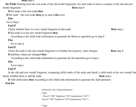
When the running model is changes, the system maintains the portfolio model with the system runtime data consistency of the model through the depth first algorithm.
Figure 3. Classroom sensing device in intelligent campus runtime model fragments.
Table 1. Three basic models.
Model
operation Description Instructions
Set ∃Type n, n in condition of Constraint∧prop∈n. properties
In the model look for a certain type and constraint elements and assignment for its attribute
Add ∃Type s, Constraint∃Type f, s∧props∈f⊆∧s. properties f in condition of as the parent node, add the type of child nodes and assignment In the model look for a certain type and constraint elements
Remove ∀Type n, n not in condition of Constraint In the model look for a certain type and constraint elements and delete them
5. Intelligent Campus Wireless Sensor Network Model Transformation
Method Based on the Runtime Model
model to obtain the state information of objective things. In this paper, by constructing the element mapping re-lation between a portfolio model and application scenario model to implement a portfolio model to the applica-tion scenario model transformaapplica-tion, and maintain the attribute values of applicaapplica-tion scenario model elements and the corresponding elements in the portfolio model are equal. Model transformation program needs writing in order to transform the portfolio model to the application scenario model. In this article a method of model trans-formation is used based on combination model, the application scenario model and element mapping rules be-tween them, automatically generating a conversion program to the corresponding model. Table 2 shows the one-to-one, one-to-many, and many-to-one, three basic mapping relation of model elements.
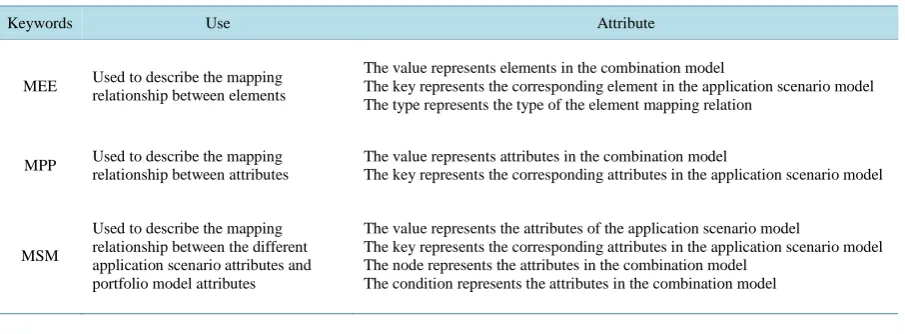
The element mapping relationship between the combination model and the application scenario model can be expressed as the combination of the three basic mapping relations. In this paper a set of mapping relationship describing rules and the method of automatically generated code is put forward, enabling the administrator to get the corresponding model transformation program by defining element mapping rules between the models. Ele-ment mapping rules between the models are described by an XML file. Keyword MEE represents mapping be-tween the elements, MPP represents mapping bebe-tween attributes and MSS represents mapping bebe-tween scena-rios and model. These definitions are as shown in Table 3.
On the basis of the above keywords, mapping rules between the elements are described according to the mod-el mapping.
[image:7.595.85.542.337.562.2]One-to-one mapping relationship between the model elements case is shown in Figure 4. “Power” type ele-ment of Combination model and “Light” type eleele-ment in the application scene model are “one-to-one” mapping
Table 2. Three basic mapping relations between the model elements.
Mapping relation Instructions Note (special)
One to one
A type of elements in portfolio model corresponds to a type of elements in application scenario model.
The corresponding attribute to the attribute of element in application scenario model can be found in the corresponding element of combination model. When a portfolio model to the application scenario model transformation occurs,
the attribute of element in application scenario model will be assigned according to the corresponding attribute of its associated elements in the array model.
One to many
A type of element in portfolio model corresponds to two or more types of elements in application scenario model.
When the model transforms, the elements of the combination model need to choose a kind of specific type of elements in application scenario mode for mapping according to their attribute information.
Many to one
Two or more types of elements in portfolio model correspond to a type of element in application scenario model.
The element attribute of application scenario model corresponding to the attribute in the portfolio model is distributed in two or more elements. In a portfolio model to the application scenario model transformation occurs, the elements in the scenario model need to query in the portfolio model and at the same time two or more elements of the assignment for its properties.
Table 3. The keywords of Element mapping rules between the models.
Keywords Use Attribute
MEE Used to describe the mapping relationship between elements
The value represents elements in the combination model
The key represents the corresponding element in the application scenario model The type represents the type of the element mapping relation
MPP Used to describe the mapping relationship between attributes
The value represents attributes in the combination model
The key represents the corresponding attributes in the application scenario model
MSM
Used to describe the mapping relationship between the different application scenario attributes and portfolio model attributes
The value represents the attributes of the application scenario model
The key represents the corresponding attributes in the application scenario model The node represents the attributes in the combination model
[image:7.595.89.542.563.730.2]Figure 4. One-to-many mapping relations between the model elements.
relationship, in which MEE labels express “Power” to “Light” elements mapping, and MPP label expresses the mapping of the attribute id in “Power” element, switch to the “Light” element attribute id, on/off.
The one-to-many mapping relationships between model elements case are shown in Figure 5. It is “one-to- many” mapping relationship between the elements of the “Tag” type element in the portfolio model and the “Light” and “Projector” type in the application scenario model. Tag elements might map for the Light or Pro-jector elements, with a group of MPP tags for the type value “multi” to represent this mapping. When the Tag elements of the type attribute value is the “Light”, the Tag element in the combination model maps for the Light elements in the application scenario model.
Many-to-one mapping relation between elements of the model can use many-to-one mapping relation of the Reader type element and Sensor element in the combination model and Classroom element in the application scenario model. The elements of Reader in the portfolio model and Classroom in the application scenarios mod-el represent room. So MEE tag and MPP tag are used to describe the two types of mod-elements and their mapping between attributes. However, Classroom element and Reader elements contain more abundant information, which is present in the Sensor elements. So the query tags are used to describe the attributes of the Sensor ele-ment to the map Room eleele-ments corresponding attribute. The key and the value points in query tags use query tags to describe the attributes of the Sensor element to the map Room elements corresponding attributes. The key and the value in query tags separately represent the element properties in the application scenario model and composite model. The node attribute value for the element of Sensor says property for Sensor, and the condition attribute value “id = self. Id” is used to describe the element conditions to be met.
Mapping rules were in strong correlation with model conversion code. Every MEE label of mapping rule ge-nerates a method of code conversion, which implements mapping of elements. Each mapper tag of mapping rules generates a simple assignment statement of conversion code, which achieves the mapping of properties. Each query tag of mapping rules generates a query and assignment statement of conversion code, which achieves lookup and mapping of attributes. Through the above definitions, model conversion code can be auto-matically generated on the basis of mapping rules.
6. Experimental Study
Figure 5. One-to-many mapping relations between the model elements.
Table 4. Experiment data of two methods.
Methods Power of the method of this paper Power of traditional solution Rate of energy saving
Data 1 9952 11,938 16.636%
Data 2 9964 11,962 16.7029%
Data 3 9982 12,001 16.8236%
Data 4 9955 11,914 16.4428%
Average 9967 11,959 16.6564%
7. Conclusion
In order to improve the universality and extensibility of the campus network system, in this article a method of intelligent campus wireless sensor network management based on the runtime model has been put forward. This method is that by constructing the runtime model, data collected from different sensing equipment are custo-mized, extracted and combined for unified management, through the mapping between the model transformation and model, thus developing or extending the intelligent campus Internet of things system rapidly for application scenario. Through experiments and compared with traditional methods, this method can more effectively man-age the campus facilities, energy saving up to 17%. In the future, this method will be applied to other application scenario on the campus, at the same time in practice further simplify programming and enhance the effect of management.
References
[1] Mottola, L. and Picco, G.P. (2011) Programming Wireless Sensor Networks: Fundamental Concepts and State of the Art. ACM Computing Surveys (CSUR), 43. http://dx.doi.org/10.1145/1922649.1922656
[2] (In Chinese).
http://baike.baidu.com/link?url=nbMN886dOOa_IXMx1cwuE4-s5lJorknGCkkihkWbXDhk7rD8XNT_SVS27tNXNZ aTeZXDvb3xYLzhfOr7GR1LTa
[3] http://sourceforge.net/projects/teenylime/
[4] (In Chinese).
http://baike.baidu.com/link?url=tfMY3dMYJeLcZ7KESmTlKSFmwZqYmLxbesDFdUp9QfbSRWYNzQLPTGpYneL IRie0NOVm2pp9bdVA6rOyQYSOVq
[5] Spiess, P., Karnouskos, S., Guinard, D., Savio, D., Baecker, O., Souza, L.M.S.D. and Trifa, V. (2009) SOA-Based In-tegration of the Internet of Things in Enterprise Services. Proceedings of the IEEE International Conferences on Web Services, Los Angeles, 6-10 July 2009, 968-975. http://dx.doi.org/10.1109/ICWS.2009.98
[6] Janowicz, K., Broring, A., Stasch, C., Schade, S., Everding, T. and Llaves, A. (2013) A Restful Proxy and Data Model for Linked Sensor Data. International Journal of Digital Earth, 6, 233-254.
http://dx.doi.org/10.1080/17538947.2011.614698
[7] Beckmann, K. and Thoss, M. (2010) A Model-Driven Software Development Approach Using OMG DDS for Wire-less Sensor Networks. Lecture Notes in Computer Science, 6399, 95-106.
http://dx.doi.org/10.1007/978-3-642-16256-5_11
[8] Thang, N.X. and Geihs, K. (2010) Model-Driven Development with Optimization of Non-Functional Constraints in Sensor Network. Proceedings of the 2010 ICSE Workshop on Software Engineering for Sensor Network Applications, Cape Town, 2-8 May 2010, 61-65. http://dx.doi.org/10.1145/1809111.1809128
Op-timization of Wireless Sensor Network Applications. Proceedings of the 2nd Workshop on Software Engineering for Sensor Network Applications, Honolulu, 21-28 May 2011, 31-36. http://dx.doi.org/10.1145/1988051.1988058
[10] Rodrigues, T., Dantas, P., Delicato, F.C., Pires, P.F., Pirmez, L., Batista, T., Miceli, C. and Zomaya, A. (2011) Model- Driven Development of Wireless Sensor Network Applications. Proceedings of IFIP 9th International Conferences on Embedded and Ubiquitous Computing, Melbourne, 24-26 October 2011, 11-18.
http://dx.doi.org/10.1109/EUC.2011.50
[11] Blair, G., Bencomo, N. and France, R.B. (2009) Models@ Run.time. Computer, 42, 22-27.
http://dx.doi.org/10.1109/MC.2009.326
[12] Wu, Y.H., Huang, G., Song, H. and Zhang, Y. (2012) Model Driven Configuration of Fault Tolerance Solutions for Component-Based Software System. Proceedings of the 15th International Conference on Model Driven Engineering Languages and Systems, Innsbruck, 30 September-5 October 2012, 514-530.
http://dx.doi.org/10.1007/978-3-642-33666-9_33
[13] Sicard, S., Boyer, F. and De Palma, N. (2008) Using Components for Architecture-Based Management: The Self-Repair Case. Proceedings of the 30thInternational Conference onSoftware Engineering, Leipzig, 10-18 May 2008, 101-110.
http://dx.doi.org/10.1145/1368088.1368103
[14] Morin, B., Barais, O., Nain, G. and Jezequel, J.M. (2009) Taming Dynamically Adaptive Systems Using Models and Aspects. Proceedings of the 31stInternational Conference onSoftware Engineering, Vancouver, 16-24 May 2009, 122- 132. http://dx.doi.org/10.1109/icse.2009.5070514
[15] Chen, X., Zhang, W., Huang, G., Li, A.P., Guo, W.Z. and Chen, G.L. (2014) Management Approach of Wireless Sen-sor Networks Based on Runtime Model. Journal of Software, 25, 1696-1712. (In Chinese)
http://www.jos.org.cn/1000-9825/4665.htm
[16] Song, H., Huang, G., Xiong, Y.F., Chauvel, F., Sun, Y.C. and Mei, H. (2010) Inferring Meta-Models for Runtime Sys-tem Data from the Clients of Management APIs. Proceedings of the 13thInternational Conference onModel Driven Engineering Languages and Systems, Oslo, 3-8 Norway 2010, 168-182.
http://dx.doi.org/10.1007/978-3-642-16129-2_13
[17] Zhang, W., Song, H. and Huang, G. (2011) Object Oriented Accessing Approach for Wireless Sensor Network Devices and Data. Journal of Frontiers of Computer Science and Technology, 5, 1076-1084. (In Chinese with English Abstract)
[18] Huang, G., Song, H. and Mei, H. (2009) SM@RT: Applying Architecture-Based Runtime Management of Internetware Systems. InternationalJournal of Software and Informatics, 3, 439-464.
[19] Song, H., Huang, G., Chauvel, F., Xiong, Y.F., Hu, Z.J., Sun, Y.C. and Mei, H. (2011) Supporting Runtime Software Architecture: A Bidirectional-Transformation-Based Approach. Journal of Systems and Software, 84, 711-723.
http://dx.doi.org/10.1016/j.jss.2010.12.009