Design of Model Predictive Control based Direct Neural
Controller for Surge Tank Application
Rashmi Baweja
Reader, Department of Electronics Engg. Modi Institute of Technology, Kota
Rajasthan, India
N. K. Bhagat,
Associate Prof., Department of Electrical Engg., Delhi Technological University,
Delhi, India
ABSTRACT
Model predictive control based direct neural controllers represent another class of computer application in the field of non-linear controls. These controllers can also be made adaptive such that the adaptation mechanism attempts to adjust a parameterized nonlinear controller to approximate an ideal controller. Various approximators such as linear mappings, polynomials, fuzzy systems, or neural networks can be used as parameterized nonlinear controller. In this paper, we proposed a model predictive control based neural network controller to control the liquid level in a surge tank, with respect to the reference input. The neural controller works on the normalized gradient-based approximator parameter update law used for a class of nonlinear discrete-time systems in direct cases. In our proposed design, the reduction in error is reached upon between the ideal and the actual controller and the direct adaptive control scheme is tested for performance via a simple surge tank example. The proposed controller algorithm performs well and can be physically implemented.
Keywords
Model predictive control, Direct neural control, Non linear systems.
1.
INTRODUCTION
The present industrial scenario emphasizes on automated control to increase the productivity and improving the quality of products. In the case of process industries, more advanced and complex control systems needs to be implemented to fulfill the present needs. The non-linear process dynamics is a major area of research in the recent years. The neural approach to computation has emerged as the solution to tackle problems for which more conventional computational approaches have proven ineffective [1]-[4]. Model predictive control (MPC) techniques have been recognized as an efficient approach to improve operating efficiency and profitability. It has become an accepted standard for complex control problems in the process industries. It can be used for the control of non-linear systems if they are working around a reference set-point.
However, if the set point is moved away from the nominal work point, the controller is less effective, or even detrimental to the system operation. One solution to this kind of control problem is to develop a non-linear model predictive control strategy. The neural networks have been shown to have good approximation capability for non-linear systems [5].
The aim of controller design is to construct a controller that generates control signals which in turn generate the desired
plant output subject to given constraints. Predictive control tries to predict, the plant output for a given control signal. This tells in advance, the effect of control, and by this knowledge the best possible control signal is chosen. Various model structures have been reported in the literature for identification of the non-linear systems. Neural network model has received much attention in the field of chemical process control as it possesses powerful function approximation properties that make them useful for representing nonlinear models or controllers [6, 7].
A large number of predictive control schemes have been developed based on various neural networks like Multi Layer Perceptron (MLP) or Radial Basis Functions (RBF). The major requirement for the successful application of non-linear MPC based on a neural network model is an accurate nonlinear model and an efficient optimization algorithm. A Multi Layer Perceptron commonly uses the back propagation learning algorithm, which is essentially a non-linear steepest descent algorithm [8]. An MLP approach for designing of NNMPC controller is presented in [9].The fuzzy systems can also be used as approximators to approximate the controller in the direct case. One good candidate of fuzzy systems is the Takagi– Sugeno fuzzy system (TSFS), which has shown to be successful in many applications [10].
In this paper, a control method based on prediction is developed for a nonlinear system of surge tank. Neural network model based on Radial basis function has been used to predict future plant behavior over a specified time horizon. The minimization routine of the control relevant cost function is based on the normalized gradient algorithm.
2.
PREDICTIVE NEURAL CONTROL
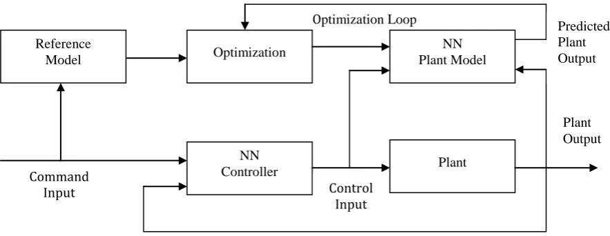
Model Predictive Control (MPC), shown in Figure 1, optimizes the plant response over a specified time horizon [11]. This architecture requires a neural network plant model, a neural network controller, a performance function to evaluate system responses, and an optimization procedure to select the best control input. The optimization procedure can be computationally expensive. It requires a multi-step ahead calculation, in which the neural network model is used to predict the plant response. The neural network controller learns to produce the input selected by the optimization process. When training is complete, the optimization step can be completely replaced by the neural network controller. Here, the neural network controller is basically a Radial Basis Function
Volume 51– No.21, August 2012
Fig 1: Generalized model predictive control structure
2.1
Radial Basis Function Networks
Radial Basis Function Networks (RBFN) consists of 3 layers, an input layer, a hidden layer and an output layer. The hidden units provide a set of functions that constitute an arbitrary basis for the input patterns. hidden units are known as radial centers. The transformation from input space to hidden unit space is nonlinear whereas transformation from hidden unit space to output space is linear. The radial basis functions in the hidden layer produce a significant non-zero response only when the input falls within a small localized region of the input space. Each hidden unit has its own receptive field in input space. An input vector which lies in the receptive field center, would activate the center and by proper choice of weights the target output is obtained. We are using the Gradient Descent Learning (On line) technique to update the weights and centers of the RBFN and the activation function is Gaussian in nature.
3.
ADAPTIVE CONTROL
In this section, a description of the system considered for control is presented, along with its direct control law. Here, we consider the SISO discrete-time system described by [12]:
) 1 ( ) 1 ( )) ( ( )) ( ( ) 1
(k f0 x k g0 xk ukd y
where f0()and g0()are unknown smooth functions, x(k)is a
vector of past inputs and outputs
Td k u d m k u k y n k
y( 1),..., ( ), ( 1),...., ( ) , where n
m , yis the output, uis the input, and dis the time delay (relative degree) of the system. It is known that for the class of systems (2), there exists an ideal controller (u(k))that drives the
output of the system to track a known reference trajectory after dsteps. Such a controller is defined as ) 2 ( )) ( ( ) ( )) ( ( ) ( 1 1 k x g k r k x f k u d d
where it can be shown by recursive substitution as in [9] that )) 1 ( ( )) ( ( 0
1
xk f xk d
fd and gd1(x(k))g0(x(kd1)). Here, we consider the same plant assumptions used in [9]. A direct adaptive controller that seeks to drive the system to track a known reference input r(k)uses an approximator that
attempts to approximate the ideal controller dynamics (u, that we assume to exist). Here, we assume that the ideal control can be approximated by
) 3 ( ) ( )) ( ), ( ( )
(k A xk rk u k
u k
T
u
where Au(k)is an approximation of the ideal parameter vector
u
A , uk(k)is the known part of the ideal control, and (x,r)is the partial of the approximator output with respect to the parameter vector. The approximator parameter error is defined as (k)Au(k)Au
.
In the direct approach, let us consider the subclass of systems
(2) which can be written as
( ( )) ( ( ))
( ) (4) )) ( ( )) ( ( ) ( )) ( ( )) ( ( )( 1 1
k u k x g k x g k x f k x f k u k x g k x f d k y k u k u d d
where fk()and gk()are the known parts of the dynamics, and )
(
u
f and gu()are the unknown parts of the dynamics further, we can consider the case where fk gk 0.
Using the certainty equivalence approach, the control law is
defined as
) 5 ( )) ( ( ˆ ) ( )) ( ( ˆ ) ( 1 1 k x g k r k x f k u d d
where ˆfd1(x(k))and gˆd1(x(k))are estimates of fd1(x(k)) and ))
( (
1 xk
gd , respectively. A projection algorithm may be used to
ensure that gˆd1(x(k))00so that the control signal is well defined. The parameter errors for the direct adaptive neural controller is defined as f(k)Af(k)Af and
g g
g(k) A (k) A
.
The error equation for direct NNMPC case can be written as ) 6 ( ) ( ) 1 () ( ) ( )) 1 ( ( ) 1
(k xk d k x k d k
e T
where, (x(k))g0(x(kd1))(00 (x(k))1, and
0
and 1are known constants related to the plant dynamics), in
Optimization Loop Reference
Model Optimization
NN
Fig 2: Diagram of surge tank system
the direct case k1. Also, (k)is function of the approximation error. For simplicity, we will write (6) as
) 7 ( ) ( ) 1 ( ) ( ) 1 ( ) 1
(k k d T k k d k
e
Here, the normalized gradient-based parameter update law that seeks to minimize the squared tracking error is used.
4.
TANK DYNAMICS
Used to regulate fluid levels in systems, surge tanks act as standpipe or storage reservoirs that store and supply excess fluid. In a system that has experienced a surge of fluid, surge tanks can modify fluctuations in flow rate, composition, temperature, or pressure. Typically, these tanks (or “surge drums”) are located downstream from closed aqueducts of feeders for water wheels. Depending upon its placement, a surge tank can reduce the pressure and volume of liquid, thereby reducing velocity. Therefore, a surge tank acts as a level and pressure control within the entire system.
To accurately model a surge tank, mass and energy balances need to be considered across the tank. From these balances, we will be able to develop relationships for various characteristics of the surge tank shown in Fig.2.
Consider the surge tank model that can be represented by the following differential equation [13]:
) 8 ( ) ( )) ( (( 1 )) ( ( ) ( 2 ) ( t u t h A t h A t gh c dt t dh r r
Where u(t) is the input flow (control input), which can be positive or negative. Also,
h
(
t
)
is the liquid level (output of the system); Ar(h(t))is the cross-sectional area of the tank;2 sec / 8 . 9 m
g is the gravitational acceleration; and
c
1
is the known cross-sectional area of the output pipe. Letb t ah t h
Ar( ()) () , where a1 and b3. Using Euler
approximation to discretize the system, we have
) 9 ( )) ( ( ) ( )) ( ( ) ( 6 . 19 ) ( ) 1 ( k h A k u k h A k h T k h k h r r
Where T0.1. Note that the system (9) belongs to the same class of systems (2), where
d
1
) 10 ( )) ( ( ) ( 6 . 19 ) ( )) ( ( 0 k h A k h T k h k x f r and ) 11 ( )) ( ( )) ( ( 0 k h A T k x g r
The system is tested for h(k)0so that the response is realistic.
5.
SIMULATION RESULTS
Testing of control quality of selected nonlinear system with RBFN based neural controller is realized in environment of MATLAB. For the purpose of testing, we used simulation models of nonlinear dynamic systems described by the differential equation. The nonlinear system has nonlinear transfer characteristic and dynamics of the system changes according to operating point. Initially, the surge tank shape parameters are characterized. The value of clogging factor representing dirty filter in pump is taken nominally as 1. Other parameters are, gravity=9.8, sampling rate=0.1, and lower and upper bounds on set point are taken as 0.25 and 0.5 respectively. The length of simulation is taken as 1000 samples. And a square wave is used as the reference input. Then the plant initial conditions are established, further the parameters of approximator are defined. The number of receptive field units taken in the RBF is 100. An optimization of no. of receptive units is reached upon by comparing the tracking error convergence rate and magnitude. It is been found that faster rate convergence with better steady state response is obtained in the designed neural controller, with 100 nos. of receptive field units.
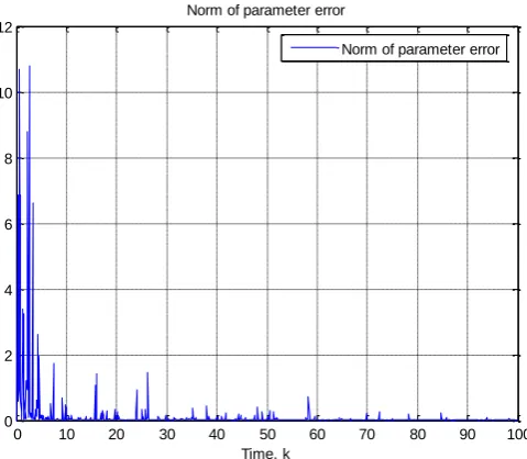
Comparison of liquid level in the tank with the reference input w.r.t. time is plotted in Fig 3. In Fig 4 a comparison of tank input and ideal feedback linearizing input is shown for length of simulation taken as 100. Quality evaluation is done by plotting the norm of parameter error in Fig. 5 and by mapping of tracking error and dead-zone width in Fig.6. In Fig. 7 and 8 it has been revealed that the neural controller is causal and stable in nature and thus it is physically realizable.
Volume 51– No.21, August 2012
[image:4.595.168.449.251.361.2]Fig 3: Comparison of liquid level in the tank and reference input w.r.t. time
[image:4.595.181.421.426.635.2]Fig 4: Comparison of tank input and ideal feedback linearizing input
Fig 5: Norm of parameter error for proposed controller
0 10 20 30 40 50 60 70 80 90 100
0 2 4 6 8
L
iq
u
id
h
e
ig
h
t,
h
Liquid level h and reference input r
liquid level h reference input r
10 20 30 40 50 60 70 80 90 100
-20 -10 0 10 20
Tank input, u and the "ideal" feedback linearizing input
Time, k
Tank input u
ideal feedback linearizing input
0 10 20 30 40 50 60 70 80 90 100
0 2 4 6 8
L
iq
u
id
h
e
ig
h
t,
h
Liquid level h and reference input r
liquid level h reference input r
10 20 30 40 50 60 70 80 90 100
-20 -10 0 10 20
Tank input, u and the "ideal" feedback linearizing input
Time, k
Tank input u
ideal feedback linearizing input
0 10 20 30 40 50 60 70 80 90 100
0 2 4 6 8 10 12
Time, k Norm of parameter error
Fig 6: Mapping of tracking error and dead-zone width
Fig 7: Direct neural controller mapping between inputs and output 10 20 30 40 50 60 70 80 90 100 -1
0 1 2 3 4 5
Time, k
Tracking error, e, and deadzone width
Tracking error Deadzone width
0 2 4 6 8 10 0
2 4
6 8
10 -5
0 5 10 15 20
Liquid height, h Direct neural controller mapping between inputs and output
Reference input, r
C
o
n
tr
o
lle
r
o
u
tp
u
t
0 2 4 6 8 10 0
2 4
6 8
10 -20
-10 0 10 20 30
Liquid height, h Ideal controller mapping between inputs and output
Id
e
a
l
c
o
n
tr
o
lle
r
o
u
tp
u
[image:5.595.163.424.517.732.2]Volume 51– No.21, August 2012
6.
CONCLUSION
The main objective of this article is to control the non linear dynamics of surge tank via neural controller. In this paper the inclusion of dynamic neural models in predictive control for a benchmark nonlinear process, surge tank is presented. A Neural network approximator model was identified using Radial Basis Function(RBF), and validated on the data generated from simulation of surge tank dynamic equations. This model represents the dynamics of the nonlinear surge tank and is used as nonlinear predictor in the discussed predictive control technique, NNMPC. The control technique is tested on reference signals which exhibits, the possible nonlinear process dynamics occurring inside a real surge tank. On analysis of the response graphs it can be seen that the NNMPC strategy successfully tracks the random reference signal. The result obtained for the random reference signal illustrates and proves the tracking ability of controller. Also almost offset free and very close set point tracking is obtained using NNMPC strategy. This RBF based algorithm performs better than MLP as it has single hidden layer and is capable of fast learning.
7.
REFERENCES
[1] Denker, J., 1986, AIP Con5 Proc. Neural Networks for Computing, American Institute of Physics, New York. [2] J. Hopfield, “Neural Networks and Physical Systems with
Emergent Collective Computational Abilities,” Proc. Nut. Acad. Sci. U.S., 1982, 79, 2554-2558.
[3] Kohonen, T., 1984. Self Organization and Associative Memory. New York: Springer-Verlag.
[4] Rumelhart, D. and McClelland, J., 1986, Parallel Distributed Processing. Cambridge, MA: MIT Press. [5] M. Morari, J.H. Lee, “Model Predictive Control: Past,
Present and Future”, Computers and Chemical Engineering, 1999, 23, 667-682.
[6] N. Bhat, T.J. McAvoy, “Use of Neural Network for Dynamic Modeling and Control of Chemical Process Systems”, Computers and Chemical Engineering, 1990, 14, 573.
[7] A. Bjarne, T.A.J. Foss, V.S. Aage, “Nonlinear Predictive Control using Local Models-Applied to a Batch Fermentation Process”, Control Engineering Practice, 1995, 3, 389.
[8] L.G. Lightbody, G.W. Irwin, “Neural Networks for Nonlinear Adaptive Control”, in Proc. IFAC Symp. Algorithms Architectures Real-Time Control, Bangor, U.K. 1992, 1–13.
[9] P. Shrivastava, A.Trivedi “Control of Nonlinear Process using Neural Network Based Model Predictive Control”
International Journal of Engineering Science and Technology (IJEST), 2011, 3, 2573-81.
[10]H.N. Nounou, K.M. Passino, “Stable Auto-Tuning of Adaptive Fuzzy/Neural Controllers for Nonlinear Discrete-Time Systems”, IEEE Transactions on Fuzzy Systems, 2004, 12, 70-83.
[11]B. ZareNezhad, A. Aminian, “Application of the Neural Network-Based Model Predictive Controllers in Nonlinear Industrial Systems. Case Study”, Journal of the University of Chemical Technology and Metallurgy, 2011, 46, 67-74. [12]F.C. Chen, H. K. Khalil, “Adaptive Control of a Class of
Nonlinear Discrete-Time Systems using Neural Networks”, IEEE Trans. Automat. Contr., 1995, 40, 791– 801.
[13]Passino, K.M., Yurkovich, S., 1998, Fuzzy Control. Menlo Park, CA: Addison-Wesley Longman.