5
IV
April 2017
Technology (IJRASET)
V/F Speed Control of Induction Motor by using
L-Z Source Inverter
Priyanka A. Jadhav1, Amruta A. Patil2, Punam P. Patil3,Supriya S. Yadav4 , Rupali S. Patil5,Renu C. Lohana6 1,2,3,4,5,6
Electrical Engineering Department, NMCOE, Shivaji University, India
Abstract: This paper presents L-Z source inverter used to control the speed of an induction motor using the V/f method. Capacitors using Z source inverters may result in large volume, expensive cost, inrush current and resonance at start up.
So to overcome this problem in Z source inverters, new topology of L-Z source inverter is used which can suppress the resonance thoroughly by removing capacitor, thus improving the efficiency of power supply. This paper also discusses about the implementation of variable speed drive to maintain constant speed of three phase induction motor.
The system is simulated in MATLAB SIMULINK as well as hardware is set up for the same. The results are presented to show the superiority of L-Z source inverter.
Keywords: L-Z source inverter, Inrush current, inductor, resonance, power converter , V/f method, Three phase induction motor.
I. INTRODUCTION
There are different methods of speed control such as stator voltage control, rotor resistance control, pole changing method and V/f method. Here, V/f control method is used because it can be used to control speed above and below rated speed.
Inverter is employed to get variable frequency from DC supply. Various types of inverters like Voltage Source Inverter(VSI), Current Source Inverter(CSI) and Z Source Inverter (ZSI) may be used.
CSI boosts voltage, whereas VSI bucks voltage. But, Z source inverter combines the advantages of CSI and VSI both to have additional boost and buck features. Z source inverter reduces high inrush current and also overcomes limitations of VSI and CSI. The Z source inverter system reduces line harmonics, improves power factor and reliability, also extends output voltage range. Trans Z source inverter also has buck and boost function that cannot be achieved by traditional VSI and CSI. It reduces voltage stress and increases voltage gain.
In this paper, L-Z source inverter is used because same drawbacks are present in Z source inverter topology mentioned as follows: l) Capacitors are used in the ZSI network, thus high voltage and large capacity capacitors should be used, which results in large volume, expensive cost and reduced life span of system. 2) It cannot suppress the inrush current and the resonance introduced by Z source capacitors and inductors at start up, thus causing voltage and current surge which may destroy the devices. Thus, to overcome these drawbacks, a new topology of L-Z Source Inverter (L-ZSI) is proposed. L-ZSI does not use capacitor and thus it enables to limit high inrush current at start up, suppresses the resonance and improves the efficiency of power supply. So, L-Z source inverter is employed to run an induction motor and control its operating speed by V/f method.
II. L-ZSOURCEINVERTER
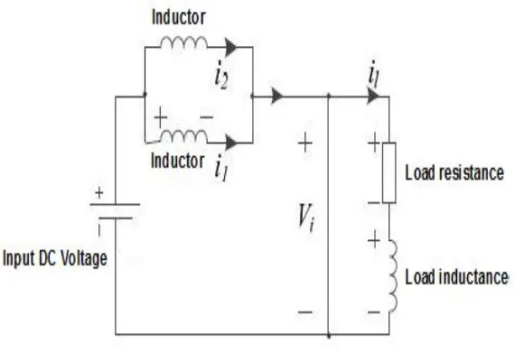
Fig. 1. shows the L-ZSI by improving the existing Z-source impedance network. The proposed inverter employs a unique inductor and diode network to couple the low DC voltage energy source to the main circuit of the inverter and avoids the disadvantage caused by capacitor in the ZSI especially in prohibiting the inrush current at startup and the resonance of Z-source capacitors and inductors. The inverter can also raise the voltage gain by adjusting shoot through duty ratio.
The number of inductors used are different to the original ZSI. The proposed L-ZSI has no capacitor and consists of two inductors (L1, L2) where L1=L2 and three diodes (D1, D2, D3) as shown in Fig. 1. The combination of L1– L2– D1– D2– D3 acts as a switched inductor cell. This topology helps in inrush current suppression, unlike the traditional topologies, as no current flows in the main circuit at the startup. There is also a common ground for the source and inverter in L-ZSI.
Technology (IJRASET)
A. Operation Mode
The operating modes of the system are explained as follows
1) Mode 1: Non-Shoot through stateIn this mode, the diodes in the upper and lower arm are in OFF state and the diode in the
[image:3.612.192.463.150.284.2]middle arm of the circuit is conducting. Thus, the two inductors are connected in series. The inductors transfer energy from the input source to the output load as shown in Fig. 2 below.
Fig. 2 Non Shoot through mode
2) Mode 2: Shoot through state In this mode, the diodes D1 and D3 both are conducting and the diode D2 is in OFF state (ref Fig.
1). The three phase inverter side is shorted by the switching devices. So the inductors in the upper and lower arm are connected in parallel and inductor stores energy in this mode. The circuit diagram is shown in Fig. 3 below.
Fig. 3 Shoot through mode
III.INDUCTIONMOTORANDV/FMETHOD
Induction motor are widely used in many residential, commercial, industrial and utility applications because of its following properties - self starting, elimination of a starting device, robust construction, higher power factor and good speed regulation. But the induction motor is a constant speed machine which makes its applications much limited. The development of speed control has been designed by combination of PWM control circuit and IGBT inverter circuit with L-Z source inverter. It is simple, robust and compact open loop system. PWM controller circuit is used to control single phase or three phase induction motor.
[image:3.612.174.459.364.564.2]Technology (IJRASET)
IV.HARDWAREDESIGNOFOPENLOOPSYSTEM
The block diagram of V/f speed control of induction motor is as shown in Fig. 4. below.
Fig.4. Block diagram of V/f speed control of induction motor
A. Components Used
1) Optocoupler: 4N25, 4N26, 4N27, 4N28 are industrial standard family of optocouplers. The 4N25 optocoupler is selected for
this project as per the ratings required. It is used as a safety component that transfers electrical signals between two isolated circuits by using light signal. It is used for reed relay driving, switch mode power supply feedback, telephone ring detection, logic ground isolation In this project, 4N25 optocoupler is used according to suitable motor rating.
2) Micro-Controller: The 8051 micro-controller is used, which is a low-power, high-performance CMOS 8-bit microcomputer
with 4K bytes of flash programmable and erasable read only memory (PEROM). The program memory can be reprogrammed in-system by the on-chip flash. By combining a versatile 8-bit CPU with Flash on a monolithic chip, the 8051 is a powerful microcomputer which provides a highly-flexible and cost-effective solution to many embedded control applications.
3) Three Terminal Voltage Regulator: A three terminal voltage regulator is a regulator in which the output voltage is set at some
predetermined value. It does not require an external feedback connection. Hence, it consists of only three terminals: input (Vin), output (Vo) and a ground terminal. As the regulator operates at a preset output voltage, the current limiting resistor used is internal to the device. The simplicity of connections to the external circuit and the minimum of external components are the advantages of such three terminal voltage regulator. Although, it offers only fixed output voltages, wide range of voltages are available, both positive and negative. The output current ranges from 100 MA to 3 A.
4) Capacitors: Capacitors store electric charge. They smoothen the pulsating DC by acting as a reservoir of charge. They may also
be used in filter circuits to remove the ripples.
5) Diode: Diode allows uni-directional flow of electricity. It used for switching purpose. Diode conducts only when it is forward
biased.
6) Transistor: Transistors amplify current. With amplification, a small current controls a gate for a greater current. A transistor
Technology (IJRASET)
[image:5.612.70.542.92.288.2]B. Hardware Implementation
Fig 5. Hardware Implementation of V/f Speed Control of Induction Motor by using L-ZSI
This circuit consists of three major parts- rectifier circuit, control circuit and IGBT driver circuit. The rectifier circuit is used to convert AC to DC. After that, LC filter is used to remove the ripple component from the DC. The pure DC voltage is given to the L-Z source inverter, which boosts DC voltage to the required value and it can be used for various applications.
The DC signal is given to the control circuit which uses the micro-controller 8051. The gating PWM pulses are produced and they are fed to the six IGBTs. The amplitude of phase voltage depends on duty cycle of PWM signal given to the inverter. The IGBT switch acts according to the gate pulses given to them and hence, the speed of the motor is controlled to the required value.
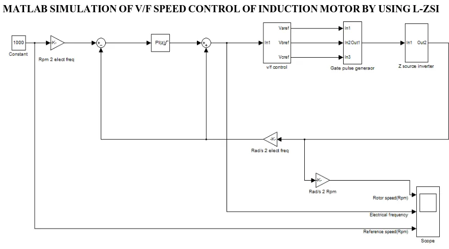
[image:5.612.97.536.402.646.2]V. MATLABSIMULATIONOFV/FSPEEDCONTROLOFINDUCTIONMOTORBYUSINGL-ZSI
Fig 6. Simulation of V/f speed control of induction motor using L-ZSI
Technology (IJRASET)
will produces the output in the form of pulses. These pulses are applied as gate signal to the inverter. Induction motor is connected across the inverter. Rotor speed is taken as output and it is compared with reference speed.
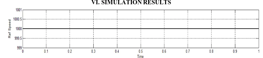
[image:6.612.93.520.114.209.2]VI.SIMULATIONRESULTS
Fig 7. Reference Speed of Induction Motor
[image:6.612.106.515.257.361.2]In Fig. 7, 1000 rpm is taken as the reference speed with respect to time.
Fig 8. Actual Speed of Induction Motor
Fig. 8 shows the actual speed time curve. After 0.2 sec, load is applied on the motor. When load is applied, motor speed decreases for small period and then again remains constant.
VII. CONCLUSION
This paper presents the speed control of induction motor using V/f control method using an L-Z Source Inverter. The system is simulated to see the different speed-torque characteristics and other parameters related to the speed of induction motor. The hardware is also implemented with the open loop system. It is observed that speed of induction motor can be controlled by changing voltage and frequency, but by maintaining V/f ratio constant. At low speed, poor torque capability is obtained.
VIII. ACKNOWLEDGMENT
We are thankful to our guide Asst. Prof. Ms. Lohana R. C. and Asst. Prof. Mr. Gijare P.P of Nanasaheb Mahadik College of Engg, Peth affiliated to Shivaji University, Kolhapur for her support and encouragement to complete this work.
REFERENCES
[1] F. Z. Peng, “Z-Source Inverter”, IEEE Trans. Industry Applications, vol 39, no.2, March/April, 2003.
[2] Fang Z Peng, MiaoesnShen and Alan Joseph, "Z-Source inverter, Control And Motor Drive Applications”, KIEE International Transactions on Electrical Machinery and Energy Conversion System, vol.5-B, no. 1,2005,pp.6-12.
[3] J. Anderson and F.Z. Peng, “Four quasi-Z-Source inverters,” in Proc. IEEE Power Electronics Spec. Conf. , ( PESC’08), pp 2743-2749.
[4] N. V. Kazimierczuk, M. K, "Small Signal Modeling Of Open Loop PWM Z-Source Converter by Circuit –Averaging Technique”, Power Electronics ,IEEE Transactions on, vol 28 ,no.3, pp.1286-1296,March 2013.
[5] Dr. P.S. Bhimbhrav “Electrical machinery”, 7th Edition, Khanna publishers, New Delhi 2010.