International Journal of Emerging Technology and Advanced Engineering
Website: www.ijetae.com (ISSN 2250-2459, Volume 2, Issue 8, August 2012)365
Efficient Electromechanical Inverter DC-AC
Devendra Panchal1, Manjushri Tambe2, Hardik Panchal31Faculty MES’S PIIT affiliated to Mumbai University & Director in DPP Electric Company Limited
2
Faculty MES’S PIIT affiliated to Mumbai University 3Faculty MES’S Pillai HOC affiliated to Mumbai University
Abstract— The inverter is one device which converts DC power in to AC power. A sine wave with 120 degree per phase total 3 phase system are use in transmit ion power grid. So we need to that equipment is directly DC power convert in to AC power with minimum loss. This machine is very useful in Renewable energy source nonconventional power generation by solar technology (P.V cells). In this system Power generation is directly in DC power form low voltage and low current. It is not suitable for grid connection. Currently we use Electronics Invertors and it is used in bank form for high voltage and high current alternate frailer and need to repair and component replace. But we have permanent solution by Electro-Mechanical invertors. It is high efficient, low maintenance easy to installation long life cycle. 100% power transfer on grid viability with minimum loss. Any amount of DC power converts to pure
AC sine wave best quality power for on line grid connection. Keywords- Ideal for grid connection Electro-Mechanical
Inverter DC-AC. (Abstract)
Keywords—Efficient Electromechanical Inverter Ideal for Grid connection use in Solar, Wind power plant.
I. INTRODUCTION
An inverter is an electrical device that converts Direct Current (DC) to Alternating Current (AC) the converted AC can be at any required voltage and frequency with the use of appropriate transformer, switching, and control circuits. Solid-state inverters have no moving parts and are used in a wide range of applications, from small switching power supply in computers, to large electricity utility high voltage direct current applications that transport bulk power. Inverters are commonly used to supply AC power from DC sources such as solar penal or batteries. The inverter performs the opposite function of a rectifier.
II. SQUARE WAVE
THE square wave output has a high harmonic content, not suitable for certain ac loads such as motors or transformers. SQUARE wave units were the pioneers of invertER DEVELOPMENT.MODIFIED sine wavE the output of a modified square wave/quasi square/modified sine wave inverter is similar to a square wave output except that the output goes to zero volts for a time before switching positive or negative.
It is simple and low cost and is compatible with most electronic devices, except for sensitive or specialized equipment, for example certain printers ease of Use Laser printer, florescent lighting, and audio equipment. Most AC motors will run off this power source albeit at a reduction in efficiency of approximately 20% multilevel inverter is power electronic systems that synthesize a desire voltage from several levels of direct current voltage as inputs. The advantages of using multilevel topology include reduction of power ratings of power devices and lower cost. There are three topologies - diode clamped inverter flying capacitor inverter and cascaded inverter. Pure Sine Wave: A pure sine wave inverter produces a nearly perfect sine wave output (less than 3% total harmonic restoration) that is essentially the same as utility-supplied grid power. Thus it is compatible with all AC electronic devices. This is the type used in grid-tie inverters. Its design is more complex, and costs more per unit power. The electrical inverter is a high-power electronic oscillator. It is so named because early mechanical AC to DC converter was made to work in
reverse, and thus was "inverted", to convert DC to AC Grid-Tie Inverter (GTI): It is a special type of inverter that
converts Direct Current (DC) electricity into Alternating Current (AC) electricity and feeds it into an existing electrical grid. GTIs are often used to convert direct current produced by many renewable energy sources, such as solar panels or small wind turbines into the alternating current used to power homes and businesses. The technical name for a grid-tie inverter is "grid-interactive inverter”. They may also be called synchronous inverters. Grid-interactive inverters typically cannot be used in standalone applications where utility power is not available. Residences and businesses that have a grid-tied electrical system are permitted in many countries to sell their energy to the utility grid. Electricity delivered to the grid can be compensated in several ways. "Net metering", is where the entity that owns the renewable energy power source receives compensation from the utility for its net outflow of power. So for example, if during a given month a power system feeds 500 kilowatt-hours into the grid and uses 100
kilowatt-hours from the grid, it would receive
International Journal of Emerging Technology and Advanced Engineering
Website: www.ijetae.com (ISSN 2250-2459, Volume 2, Issue 8, August 2012)366
In the US, net metering policies vary by jurisdiction. Another policy is a feed-in tariff, where the producer is paid for every kilowatt hour delivered to the grid by a special tariff based on a contract with Distribution Company or other power authority. In the United States, grid-interactive power systems are covered by specific provisions in the National Electric Code, which also mandates certain requirements for grid-interactive inverters US, net metering policies vary by jurisdiction. Another policy is a feed-in tariff, where the producer is paid for every kilowatt hour delivered to the grid by a special tariff based on a contract with Distribution Company or other power authority. In the United States, grid-interactive power systems are covered by specific provisions in the National Electric Code, which also mandates certain requirements for grid-interactive inverters. Pure sine wave is only applicable for the direct connection to the low power grid line. And it should be matched with 3 phase R- R phase, Y- Y phase and B-B phase at same voltage with same frequency
III. EFFICIENT ELECTROMECHANICAL INVERTER (EEI)
Inverters take DC power and invert it to AC power so it can be fed into the electric utility company grid. The grid tie inverter must synchronize its frequency with that of the grid (e.g. 50 or 60 Hz) using a local oscillator and limit the voltage to no higher than the grid voltage. A high-quality modern GTI has a fixed unity power factor, which means its output voltage and current are perfectly lined up, and its phase angle is within 1 degree of the AC power grid. The inverter has an on-board computer which will sense the current AC grid waveform, and output a voltage to
correspond with the grid.
Grid-tie inverters are also designed to quickly disconnect from the grid if the utility grid goes down. This is an NEC requirement that ensures that in the event of a blackout, the grid tie inverter will shut down to prevent the energy it produces from harming any line workers who are sent to fix the power grid. Properly configured, a grid tie inverter enables a home owner to use an alternative power generation system like solar or wind power without extensive rewiring and without batteries. If the alternative power being produced is insufficient, the deficit will be sourced from the electricity grid.
Figure-1 Four starts warm & gear set
Figure-2 Single phase Alternator
IV. WORM GEAR
International Journal of Emerging Technology and Advanced Engineering
Website: www.ijetae.com (ISSN 2250-2459, Volume 2, Issue 8, August 2012)367
Instead, the lead angle, which is equal to 90 degrees minus the helix angle, is given. In a worm-and-gear set, the worm can always drive the gear. However, if the gear attempts to drive the worm, it may or may not succeed. Particularly if the lead angle is small, the gear's teeth may simply lock against the worm's teeth, because the force component circumferential to the worm is not sufficient to overcome friction. Worm-and-gear sets that do lock are called self locking, which can be used to advantage, as for instance when it is desired to set the position of a mechanism by turning the worm and then have the mechanism hold that position. An example is the machine head found on some types of stringed instruments. If the gear in a worm-and-gear set is an ordinary helical gear only a single point of contact will be achieved. If medium to high power transmission is desired, the tooth shape of the gear is modified to achieve more intimate contact by making both gears partially envelop each other. This is done by making both concave and joining them at a saddle point this is called a cone-drive.
V. FOUR START WORM &GEAR SET
Non reverse gear set (4 starts warm gear set) us as non return path for electricity. This attachment is rotate only one direction and directly connects to the (LSA) Low Speed Alternator multi pole designed which is produce 230 volts 3phase four wire system electricity this generated power connects to the (LPG) Low Power Grid, When the inverter run by the (DCPM) DC prime mover current flow towards the grid and power transmit from the inverter to the grid. If any circumstance stops the inverter the attached protection circuit breaker (RCB) Rotary Circuit Breaker will be cut the connection and all instruments will be safe. And when restart the inverter the (RCB) automatically on and make the circuit closed and the supply start and power transmit to the grid without any difficulty. This all function will be work (ACS) Automatic Control System as per here given bellow flow chart.
Figure-3 Single Start Warm & Gear Set
Solar Penal EEI Grid line R Y B
Earthling connection
Figure-4 Flow chart of Electromechanical Inverter
R-R, Y-Y, B-B
Figure-5 Three phase grid connection
VI. FLOW CHART
Here I had used High Efficient Electromechanical Inverter (HEEMI) to connect my small 5 Kilowatts power generation solar power plant directly to the (LPG) Low power Grid. One Technical Demonstration Model Specification (TDMS) data are as follows:
1) Grid line voltage: 250 (50 Hz.) Sine wave.
2) Line Circuit breaker (LCR) 220/250 Volts.
3) Rotary Circuit Breaker (RCB) 220/250 Volts.
4) Solar penal 48 volts /5 Amp. 240 watts total 20 penal mounted modular series and parallel connection total output 240 volts 20 amperes and power 5000 watts D.C (5kw). As per light intensity available 5 hrs per day except monsoon weather.
5) Electro Mechanical Inverter (EMI) 3phase 500
International Journal of Emerging Technology and Advanced Engineering
Website: www.ijetae.com (ISSN 2250-2459, Volume 2, Issue 8, August 2012)368
6) AC pure sine Wave at the power factor 0.8 on output terminal to connect the grid.
7) Alternator 250 volt AC 500 rpm brush less air cooled.
8) Prime mover is D.C motor 240 volts 3000 rpm
9) Rotary Circuit Breaker (RCB) cum rpm controller
gear box ratio is 6:1.
VII. SINGLE PHASE ALTERNATOR
A generator that produces a single, continuously alternating voltage is known as a Single phase alternator. All of the alternators that have been discussed so far fit this definition. The stator (armature) windings are connected in series. The individual voltages, therefore, add to produce a single-phase ac voltage. Above figure shows a basic alternator with its single-phase output voltage. The definition of phase as you learned it in studying ac circuits may not help too much right here. Remember, "out of phase" meant "out of time." Now, it may be easier to think of the word phase as meaning voltage as in single voltage. The need for a modified definition of phase in this usage
will be easier to see as we go along. Single-phase alternators are found in many applications.
They are most often used when the loads being driven are relatively light. The reason for this will be more apparent as we get into multiphase alternators (also called polyphone). Power that is used in homes, shops, and ships to operate portable tools and small appliances is single-phase power. Single-phase power alternators always generate single-phase power. However, all single-single-phase power does not come from single-phase alternators. This will sound more reasonable to you as we get into the next subjects.
Synchronous speeds: The output frequency of an alternator depends on the number of poles and the rotational speed. The speed corresponding to a particular frequency is called the synchronous speed for that frequency. Rotational speeds are given in revolutions per minute (RPM)
Frequencies: These are given in Hertz (Hz)More generally, one cycle of alternating current is produced each time a pair of field poles passes over a point on the stationary
N = 120f/p = rpm
VIII. WINDING THE RELATION BETWEEN SPEED AND
FREQUENCY
Frequency is where the frequency in Hz is (cycles per second). (P) is the number of poles (2, 4, 6...) and (N) is the rotational speed in revolutions per minute (RPM).
Very old descriptions of alternating current systems sometimes give the frequency in terms of alternations per minute, counting each half-cycle as one alternation; so 12,000 alternations per minute correspond to 100 Hz. We maintained rpm of alternator to keep up 50 Hz cycle per second by help of the Mechanical Governor (M.G.) to control the speed of prime mover In three phase power output and at low speed auto circuit break and concern cover-up required speed automatic closed the circuit and power transfer to the grid and vice versa.
Figure-6 Three Phase Electronics Inverter
IX. COLOR CODE
In India three phase four wire grid connection system work and its color code are indicate (R)phase – Red, (Y)phase –Yellow and (B)phase – Blue, and (BL) Black is Earthling connection is Neutral(Black). Three phase alternator 120 degree phase difference as per RYB phase and Neutrals is connected to earth. By help of Earthling plate copper metals.
International Journal of Emerging Technology and Advanced Engineering
Website: www.ijetae.com (ISSN 2250-2459, Volume 2, Issue 8, August 2012) [image:5.612.343.567.134.351.2]369
TABLE I
FREQUENCY RPM EXAMPLES
Number
of poles
RPM for 50 Hz
RPM for 60 H z
RPM
for
400
Hz
2 3,000 3,600 24,000
4 1,500 1,800 12,000
6 1,000 1,200 8,000
8 750 900 6000
10 600 720 4800
12 500 600 4000
14 428.6 514.3 3429
16 375 450 3000
18 333.3 400 2667
20 300 360 2400
[image:5.612.339.568.147.538.2]40 150 180 1200
Figure-8 Elevation view of Governor
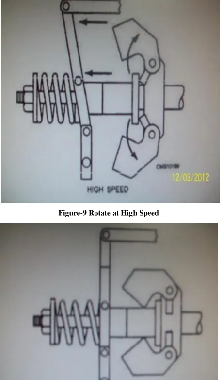
[image:5.612.64.287.148.680.2]Figure-9 Rotate at High Speed
Figure-10 Rotate Low Speed
X. MECHANICAL FLY WEIGHT ROTATING SPEED
GOVERNOR
[image:5.612.339.564.357.575.2]International Journal of Emerging Technology and Advanced Engineering
Website: www.ijetae.com (ISSN 2250-2459, Volume 2, Issue 8, August 2012)370
The centrifugal force varies with the speed of the engine. Transmitted to the fuel system through a connecting linkage, the tension of the spring (or springs) tends to increase the amount of fuel delivered to the cylinders. On the other hand, the centrifugal force of the rotating weights, through connecting linkage, tends to reduce the quantity of fuel injected. When the two opposing forces are equal, or balanced, the speed of the engine remains constant to show how the governor works when the load increases and decreases, let us assume you are driving a truck in hilly terrain. When a truck approaches a hill at a steady engine speed, the vehicle is moving from a set state of balance in the governor assembly (weights and springs are equal) with a fixed throttle setting to an unstable condition. As the vehicle starts to move up the hill at a fixed speed, the increased load demands result in a reduction in engine speed. This upsets the state of balance that had existed in the governor. The reduced rotational speed at the engine results in a reduction in speed, and, therefore, the centrifugal force of the governor weights. When the state of balance is upset, the high-speed governor spring is allowed to expand,
XI. APPLICATION
1. Efficient Electro Mechanical Inverter (EEMI) is use to low power generation power plant to
connect directly to the Low Power Grid (LPG).
2. This power generates by renewable energy
sources Solar / Wind or any other Vibration and Tide energy sources.
3. These are all low electro motive force produce power plant (EMF). So ideal for high efficiency and highest safety required and the all circumstance in EEMI.
Figure-11 Change over switch (3 phase)
XII. CHANGE OVER SWITCH
The change over switch is very useful to power transmission at online single phase or three phases at the time of on line change to grid line to users line and generator line to grid line. Over grid line is three phase all the time on and our power plant line is also on time to connection with power grid for power transmission. Without change over switch we cannot make connection to the power grid. Whether it is manually operated or by automatically operated. This change over switch is use to protect the power plant also by circuit breaker between the power grid and power plant.
ON GRID
D.C.INPUT OFF GRID
Figure-12 Efficient Electromechanical Inverter
Lay out
XIII. FUTURE SCOPE
100% Commercially Renewable power generation in low and high power transmitter with low cost and good power quality can be developed. This Electromechanical Inverter (EEI) is very use full to Solar Wind Hydro Hybrid (SWHH) power plant to connect directly on grid.
XIV. ACKNOWLEDGEMENT
PIIT, New Panvel (Mumbai University), India.
Vin Power group of Vin Care Wealth Advisory Services PVT.LTD.
International Journal of Emerging Technology and Advanced Engineering
Website: www.ijetae.com (ISSN 2250-2459, Volume 2, Issue 8, August 2012)371
REFERENCES
[1] Wikipedia, books and Thompson, Silvanus P., Dynamo- Electric Machinery, A Manual for Students of Electro techniques, Part 1, Collier and Sons, New York, 1902White, Thomas H.,"
Alternator-Transmitter Development(1891-1920)".Early Radio History us. How stuff works" Transmission Basics” Norton 2004, p. 462
[2] M.J.T. Lewis: "Gearing in the Ancient World", Endeavour, Vol. 17, No. 3 (1993), pp. 110–115 (110)The Anti key
there Mechanism Research Project: Why is it so important?, Retrieved 2011-01-10 Quote: "The Mechanism is thought to date from between 150 and 100 BC"ANSI/AGMA 1012-G05, "Gear Nomenclature, Definition of Terms with Symbols".
[3] Kurume, R.S, Theory of Machines, S.CHAND Doughty and Valance give the following information on helical gear
speeds: "Pitch-line speeds of 4,000 to 7,000 fpm 20 to 36 m/s] are common with automobile and turbine gears, and speeds of 12,000 fpm [61 m/s] have been successfullyused."p.281.
[4] Canfield, Stephen (1997), "Gear Types" Dynamics of Machinery, Tennessee Tech University, Department of Mechanical Engineering,
ME 362 lecture notes,