MURDOCH RESEARCH REPOSITORY
http://researchrepository.murdoch.edu.au/
This is the author’s final version of the work, as accepted for publication following
peer review but without the publisher’s layout or pagination.
The definitive version is available at
http://dx.doi.org/10.1109/TPEL.2006.883547
Dahidah, M.S.A., Agelidis, V.G. and Rao, M.V. (2006) On abolishing symmetry
requirements in the formulation of a five-level selective harmonic elimination
pulse-width modulation technique. IEEE Transactions on Power Electronics,
21 (6). pp. 1833-1837.
http://researchrepository.murdoch.edu.au/12053/
Copyright © 2006 IEEE
Personal use of this material is permitted. However, permission to reprint/republish
this material for advertising or promotional purposes or for creating new collective
Letters
On Abolishing Symmetry Requirements in the Formulation of a Five-Level
Selective Harmonic Elimination Pulse-Width Modulation Technique
Mohamed. S. A. Dahidah
, Member, IEEE
, Vassilios G. Agelidis
, Senior Member, IEEE
, and Machavaram V. Rao
Abstract—Selective harmonic elimination pulse width modula-tion (SHE–PWM) techniques offer a tight control of the harmonic spectrum of a given voltage waveform generated by a power elec-tronic converter along with a low number of switching transitions. These optimal switching transitions can be calculated through Fourier theory, and for a number of years quarter-wave and half-wave symmetries have been assumed when formulating the problem. It was shown recently that symmetry requirements can be relaxed as a constraint. This changes the way the problem is formulated, and different solutions can be found without a com-promise. This letter reports solutions to the switching transitions of a five-level SHE–PWM when both the quarter- and half-wave symmetry are abolished. Only the region of high-modulation indices is reported since the low-modulation indices region re-quires a unipolar waveform to be realized. Selected simulation and experimental results are reported to show the effectiveness of the proposed method.
Index Terms—Five-level inverter, inverter control, non-symmet-rical pulsewidth modulation (PWM), selective harmonic elimina-tion (SHE).
I. INTRODUCTION
S
ELECTIVE harmonic elimination pulsewidth modulation techniques (SHE–PWM) have been mainly developed for two- and three-level converter schemes (i.e., bipolar and unipolar waveforms) [1]. The main challenge associated with SHE–PWM techniques is to obtain the analytical solution of the resultant system of non-linear transcendental equations that contain trigonometric terms which in turn provide multiple sets of solutions. This has been reported in numerous tech-nical articles [2]–[5]. Several algorithms have been reported in the technical literature concerning methods of solving the resultant nonlinear transcendental equations which describe the SHE–PWM problem. These algorithms include the well-known iterative approach [6], [7], elimination theory [5], Walsh functions [8], optimization techniques [2], [3] and genetic algorithms [4], [9], and [10].On the other hand, multilevel converters have drawn tremen-dous attention in recent years and have been studied for sev-eral high-voltage and high-power applications [11]. Switching
Manuscript received March 16, 2006; revised August 18, 2006. Recom-mended by Associate Editor P. L. Chapman.
M. S. A. Dahidah is with the Faculty of Engineering, Multimedia Univer-sity, Cyberjaya 63100, Malaysia (e-mail: [email protected]; mohamed. [email protected]).
V. G. Agelidis is with the School of Electrical, Energy and Process Engineering, Murdoch University, Murdoch 6150, Australia (e-mail: [email protected]).
M. V. Rao is with the Faculty of Engineering and Technology, Multimedia University, Melaka 75450, Malaysia.
Digital Object Identifier 10.1109/TPEL.2006.883547
losses in these high-power, high-voltage converters represent an issue. Any switching transitions that can be eliminated without compromising the harmonic content of the final waveform are considered advantageous. Numerous topologies have been in-vestigated and widely studied [11]. The desired output of a mul-tilevel converter is synthesized with several methods including staircase modulation, sinusoidal PWM with multiple triangular carriers, and multilevel space-vector modulation. SHE–PWM methods have been introduced to multilevel converters in sev-eral technical articles. Initially the switching frequency was re-stricted to line frequency and therefore, the staircase multilevel waveform was arranged in such a way as to control the funda-mental and eliminate the low-order harmonic from the wave-form [4]. A new active harmonic elimination technique was re-cently introduced to the line-frequency method aiming to elimi-nate higher orders of harmonics by simply generating the oppo-site of the harmonics to cancel them [5]. Another variation of the multilevel SHE–PWM method is the unipolar case waveform where the waveform takes a positive, zero and negative value, and a phase-shifted technique is used between the converters to build the multilevel system control [12], [13]. Other approaches have also been reported including one where harmonic elim-ination is combined with a programmed method [4] and an-other where a criterion based on power equalization between various cascaded connected H-bridge multilevel converters is used to obtain the angles of the harmonic elimination method [14]. More recently, multilevel SHE–PWM defined by the well-known multicarrier phase-shifted PWM (MPS–PWM) was pro-posed in [15] where the modulation index defines the distribu-tion of the switching angles. The problem of SHE–PWM is then applied to a particular operating point aiming to obtain the op-timum position of these switching transitions that offers elim-ination to a selected order of harmonics. The main advantages of the method included an increased bandwidth for the same switching transitions and higher dc bus utilization.
However, in the previously mentioned approaches, the problem was formulated with quarter-wave symmetry constraints where the solutions to the switching transitions are sought in the region between 0 and 2. This restriction could result in sub-optimal solutions with regards to the uncontrolled harmonic distribution. Furthermore, the harmonics can only be in phase or out of phase. References [16]–[18] suggested that the constraint of quarter-wave symmetry can be relaxed to half-quarter-wave symmetry where all the even harmonics are zero but the harmonic phasing is free to vary. The advantages of generalizing the problem definition to not require quarter-wave symmetry include finding several solutions not obtainable using the classic symmetrical approach and the flexibility to select uncontrolled harmonic content.
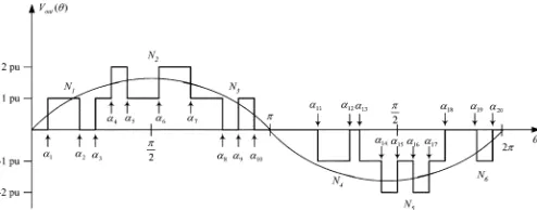
Fig. 1. Five-level defined non-symmetrical SHE–PWM waveform generation for 1< m <2.
This may in return result in further overall improvements asso-ciated with the PWM method in question. References [16] and [17] also presented solutions for both single- and three-phase cases (i.e., triplen harmonics are controlled and uncontrolled, respectively) and studied the effect of varying the phase angle of the fundamental to the harmonic profile. However, only two-and three-level waveforms were reported. Although the tech-nique was extended to a generalized multilevel case (i.e., -level, -harmonic) where the problem becomes more complicated, es-pecially when the switching angles are relaxed between 0 and 2 , solutions for higher than the three-level waveform were not presented. In [18], several multilevel waveforms are published demonstrating the generalization of [16] and [17] in the -level -harmonic case. However, in [18] a continuum of solutions across a variety of modulation indices is not provided.
The main contribution of this letter is to report solutions and results for a novel five-level PWM technique when both the quarter- and the half-wave symmetries are abolished. Although only the five-level case is presented here, the proposed method can be equally applied to any number of levels and for any number of switching transitions provided the algorithm converges. The switching transitions of the proposed method and for the region of high modulation indices are presented. Selected experimental results are provided to support the theoretical considerations.
The letter is organized in the following way. Section II de-scribes in detail the proposed five-level SHE–PWM. The case when a five-level converter is implemented with 20 switching transitions within an entire period is discussed in Section III. The resulting voltage waveform with its spectrum for a given operating point of the inverter is plotted using a software pro-gram and is experimentally verified. Conclusions are summa-rized in Section IV.
II. PROPOSEDFIVE-LEVELSHE–PWM
The proposed five-level SHE–PWM technique is defined ac-cording to the example waveform shown in Fig. 1. The mul-tilevel converter considered in the implementation of the tech-nique is composed of two cascaded H-bridge converters with equal dc sources and therefore the number of levels of the
wave-form is assumed to be five, (i.e., 2 p.u., 1 p.u., 0 p.u., 1 p.u., and 2 p.u.). However, it should be noted that other multilevel con-verter topologies could be made to operate with the proposed technique. Let be the number of total switching transitions (angles) of the waveform sought within the full period of the waveform (i.e., is relaxed between 0 and 2 ). However, is chosen to be an even number so as to have the same number of switching transitions (i.e., notches) in both the positive and neg-ative half-cycle, thereby guaranteeing that the resultant wave-form is realizable and physically correct. A closer inspection of the waveform shown in Fig. 1 reveals that there are six different regions of operation described as follows.
Let be the number of switching transitions placed between the 0 p.u. level and 1 p.u. This number can only be odd, since the first switching transition is chosen to be from the 0 p.u. to 1 p.u. level. Let be the number of switching transitions placed between the 1 p.u. level and 2 p.u. This number can only be even, since we have only a five-level waveform. Let be the number of switching transitions placed between the 1 p.u. level and the 0 p.u. This number again can only be odd. Let be the number of switching transitions placed between the 0 p.u. level and 1 p.u. This number also can only be odd, since the first switching transition is chosen to be from the 0 p.u. to 1 p.u. level. Let be the number of switching transitions placed be-tween the 1 p.u. level and 2 p.u. This number can only be an even number, so as to have a five-level waveform. Finally, let be the number of switching transitions placed between the 1 p.u. level and 0 p.u. This number can only be odd, since the first switching transition is chosen to be from the 0 p.u. to 1 p.u. level. It is worth noting that should be equal to the sum of all these transitions (i.e., )
The Fourier series expansion of the waveform presented in Fig. 1 is given by
(1) where
and (2) (3) Assuming a unity dc level (1 p.u.) for each inverter cell, the generalized expressions of and for the proposed five-level converter are given by (4)–(6), shown at the bottom of the page, where
and and is the th switching transition (angle).
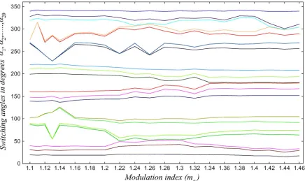
Fig. 2. Switching angles solution versus modulation indexm . (Color version of Fig. 2 is available online at http://ieeexplore.org.)
Unlike the case of a waveform having quarter- and half-wave symmetry, the proposed formulation results in a dc component and all even harmonics. These are no longer equal to zero and therefore need to be controlled. Hence, for switching transi-tions (angles), 1 harmonics can be controlled/eliminated, including the fundamental, provided that solutions exist. One of the remaining two degrees of freedom is used to control the dc component at zero level; utilization of the second one remains an open question [17].
The problem defined by (4)–(6) can be solved using any of the techniques that have been previously applied to the case of the more restrictive quarter-wave symmetry problem, including iterative approaches [6], [7], resultant theory [5], minimization techniques [2], [3], and [15] or genetic algorithms [4], [9], and [10]. Any sets of solutions resulting from the case where the quarter- or half-wave symmetry are followed will also be a solution to the more generalized formulation proposed in this letter. The minimization technique, assisted with a real-coded hybrid genetic algorithm in order to reduce the computational burden associated with the nonlinear transcendental equations of the SHE–PWM method proposed in [9] and [10], has been applied to investigate the proposed five-level converter. Details regarding the proposed hybrid genetic algorithm can be found in [10].
In order to proceed with the optimization/minimization tech-nique, an objective function describing a measure of effective-ness of the proposed method is specified as
(7) where
(8) where is the fundamental component to be generated and (0 2). It is worth noting that the proposed method
is investigated at high modulation indices only; it is implied that the low-modulation indices are satisfied with a three-level SHE–PWM technique which has been addressed in [15]. Therefore, the modulation indices in this letter will be searched from 1 to 2 (i.e., 1 2), although there is no guarantee that solutions will be found for the entire interval.
The optimal switching angles are generated by minimizing (7) when it is subject to the constraints of (9) and (10). Con-sequently, selected harmonics are minimized. These switching angles are generated for different values of and then stored in look-up tables to be used to control the inverter for a given operating point
(9) (10) where the constraints ensure that the solution is physically re-alizable and the waveform can be implemented for the given five-level converter. It should be noted that the above constraints are imposed to ensure that the switching transitions are equal between the positive and negative half cycles of the waveform, recognizing at the same time that the space of the overall solu-tions is reduced.
III. SIMULATION ANDEXPERIMENTALRESULTS
Fig. 3. Output voltage waveform (simulation,m =1.3).
Fig. 4. Spectrum of the output voltage (simulation,m =1.3).
investigated. It is also confirmed that multiple sets of solutions exist. However, the evaluation to identify the optimal set that offers a better performance is once again beyond the scope of this letter. Therefore, only one continuous set is reported. Fig. 2 shows the solution of the switching angles (i.e., ) for a certain range of 1.10 1.46 .
An operating point of 1.3 was chosen and first simulated using the PSIM software package [19] to illustrate the effectiveness of the proposed method. The output voltage waveform is shown in Fig. 3, where it is clearly illustrated that the switching transitions are distributed throughout the period without any restriction of meeting half- and/or quarter-wave symmetries. Fig. 4 depicts the spectrum of the output voltage where the absence of the selected harmonics (even and odd) is evident and the fundamental is maintained at a pre-defined value (1.3 p.u.). On the other hand, the next significant harmonic that appears in the output waveform is the tenth, confirming the theoretical considerations of the proposed technique.
A low-power laboratory five-level inverter prototype based on the two insulated-gate bipolar-transistor H-bridges config-uration was developed and tested to verify the feasibility and
Fig. 5. Output voltage waveform (experimental,m =1.3).
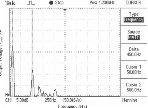
Fig. 6. Spectrum of the output voltage (experimental,m =1.3). (Cursor 1 is on the fundamental component (50 Hz) and cursor 2 is on the next significant harmonic i.e., 10250 Hz).
validity of theoretical and simulation findings. The pre-calcu-lated PWM signals are implemented using a low-cost, high-speed Texas Instruments TMS320F2812 digital signal processor (DSP) board with an accuracy of 20 s. A digital real-time os-cilloscope (Tektronix TDS210) was used to display and capture the output waveforms. The spectrum of the output voltage was obtained with a feature of the fast Fourier transformer.
IV. CONCLUSION
A novel five-level SHE–PWM technique for voltage-source converters has been proposed in this letter. The problem of finding the switching transitions is reformulated without requiring quarter- and half-wave symmetry for the output waveform. An efficient optimization/minimization technique assisted with a hybrid genetic algorithm is applied to find the switching transitions (i.e., angles) for a valid modulation index value of the fundamental component. Although multiple sets of solutions have been found, only a continuous one is reported due to space limitations. Selected simulation and experimen-tally verified results are presented to confirm the validity of the theoretical analysis.
REFERENCES
[1] P. N. Enjeti, P. D. Ziogas, and J. F. Lindsay, “Programmed PWM tech-niques to eliminate harmonics: A critical evaluation,”IEEE Trans. Ind. Appl., vol. 26, no. 2, pp. 302–316, Mar./Apr. 1990.
[2] V. G. Agelidis, A. Balouktsis, I. Balouktsis, and C. Cossar, “Multiple sets of solutions for harmonic elimination PWM bipolar waveforms: Analysis and experimental verification,”IEEE Trans. Power Electron., vol. 21, no. 2, pp. 415–421, Mar. 2006.
[3] V. G. Agelidis, A. Balouktsis, and I. Balouktsis, “On applying a min-imization technique to the harmonic elimination PWM control: the bipolar waveform,”IEEE Power Electron. Lett., vol. 2, no. 2, pp. 41–44, Jun. 2004.
[4] B. Ozpineci, L. M. Tolbert, and J. N. Chiasson, “Harmonic optimiza-tion of multilevel converters using genetic algorithms,”IEEE Power Electron. Lett., vol. 3, no. 3, pp. 92–95, Sep. 2005.
[5] Z. Du, L. M. Tolbert, and J. N. Chiasson, “Active harmonic elimination for multilevel converters,”IEEE Trans. Power Electron., vol. 21, no. 2, pp. 459–469, Mar. 2006.
[6] H. S. Patel and R. G. Hoft, “Generalized techniques of harmonic elim-ination and voltage control in Thyristor inverters: Part I—harmonic elimination,”IEEE Trans. Ind. Appl., vol. IA-9, no. 3, pp. 310–317, May/Jun. 1973.
[7] H. S. Patel and R. G. Hoft, “Generalized techniques of harmonic elimi-nation and voltage control in Thyristor inverters: Part II—voltage con-trol techniques,”IEEE Trans. Ind. Appl., vol. IA-10, no. 5, pp. 666–673, Sep./Oct. 1974.
[8] T. J. Liang, R. M. O’Connnell, and R. G. Hoft, “Inverter harmonic reduction using Walsh function harmonic elimination method,”IEEE Trans. Ind. Electron., vol. 12, no. 6, pp. 971–982, Nov. 1997.
[9] M. S. A. Dahidah and V. G. Agelidis, “A hybrid genetic algorithm for selective harmonic elimination control of a multilevel inverter with non-equal dc sources,” inProc. 6th IEEE Power Electron. Drives Syst. Conf., 2005, pp. 1205–1210.
[10] M. S. A. Dahidah and M. V. C. Rao, “A hybrid genetic algorithm for selective harmonic elimination PWM AC/AC converter,” J. Elect. Eng.Jan. 2006 [Online]. Available: http://www.springer.com/ [11] L. Rodriguez, L. Jih-Sheng, and F. Z. Peng, “Multilevel inverters: A survey of topologies, controls, and applications,”IEEE Trans. Ind. Electron., vol. 49, no. 4, pp. 724–738, Aug. 2002.
[12] L. Li, D. Czarkowski, Y. Liu, and P. Pilay, “Multilevel selective harmonic elimination PWM technique in series-connected voltage in-verters,”IEEE Trans. Ind. Appl., vol. 36, no. 1, pp. 160–170, Jan./Feb. 2000.
[13] Z. Du, L. M. Tolbert, and J. N. Chiasson, “Harmonic elimination in multilevel converter with programmed PWM method,” inProc. IEEE Ind. Appl. Soc. Annu. Meeting, 2004, pp. 2210–2215.
[14] J. Vassallo, J. C. Clare, and P. W. Wheeler, “A power-equal-ized harmonic elimination scheme for utility-connected cascaded H-bridge multilevel converters,” inProc. IEEE IECON’03, 2003, pp. 1185–1190.
[15] V. G. Agelidis, A. Balouktsis, I. Balouktsis, and C. Cossar, “Five-level selective harmonic elimination PWM strategies and multicarrier phase-shifted sinusoidal PWM: A comparison,” inProc. IEEE Power Elec-tron. Spec. Conf., 2005, pp. 1685–1691.
[16] J. R. Wells, B. M. Nee, P. L. Chapman, and P. T. Krein, “Selective harmonic control: A general problem formulation and selected solutions,” IEEE Trans. Power Electron., vol. 20, no. 6, pp. 1337–1345, Nov. 2005.
[17] J. R. Wells and P. L. Chapman, “Generalization of selective harmonic control/elimination,” inProc. IEEE Power Electron. Spec. Conf., 2004, pp. 1358–1362.
[18] J. Wells, “Generalized Selective Harmonic Control,” Ph.D. disserta-tion, Univ. Illinois at Urbana-Champaign, Urbana, IL, 2006. [19] PSIM Software Package, version 6.0, Powersim, Inc. [Online].