Speed Control of Induction Motor using Vector
Control Technique
Viji R. Rajesh S.
Assistant Professor Assistant Professor
Department of Electrical & Electronics Engineering Department of Electrical & Electronics Engineering Adithya Institute of Technology, Coimbatore, Tamilnadu,
India
Adithya Institute of Technology, Coimbatore, Tamilnadu, India
Harini S. Assistant Professor
Department of Electrical & Electronics Engineering Adithya Institute of Technology, Coimbatore, Tamilnadu, India
Abstract
This paper presents design and implementation of vector control of induction motor. This method leads to be able to adjust the speed of the motor by control the frequency and amplitude of the stator voltage of induction motor, the ratio of stator voltage to frequency should be kept constant, which is called as V/F or vector control of induction motor drive. This paper presents a comparative study of open loop and close loop V/F control induction motor. The V/F control is based on advent of stator voltage derivatives. Simulation is carried out in MATLAB/SIMULINK environment and results are compared for speed control of induction motor.
Keywords: Vector Control (V/F), Induction Motor (IM), Open Loop V/F Control, Closed Loop V/F Control, PI Controller
_______________________________________________________________________________________________________
I. INTRODUCTION
The V/F controlled drives parameters are independent, easy to implement and low cost but they are classified as inferior performance of electrical drives. [1] Vector controlled drives give somewhat inferior performance than the other control sche mes but they are the easy to implement. In V/F control methods, the stator voltage is adjusted in a part of the supply frequency, except for low and above base speeds. At low frequency operation the voltage drop across stator resistance must be taken into account. The simplest stator resistance compensation method consists of boosting the stator voltage to compensate the voltage drop across the stator resistance [5, 6]. However, it is not easy to determine the boost voltage as it is easy to get flux saturated [2, 3, 5, 6]. Alternatives to the simple boost voltage are described in [6]-[3]. However these methods need machine parameters and are complicated [1, 3]. The open Loop V/F method always suffers from oscillations especially under light load conditions [1, 9, 5, 8]. Many studies in relation to this instability problem have been carried out [7]-[8].
II. OPEN LOOP V/F CONTROL
The open loop V/F control of an induction motor is the most common method of speed control because of its simplicity and these types of motors are widely used in industry. Traditionally, induction motors have been used with open loop 50Hz power supplies for constant speed applications.
For adjustable speed drive applications, frequency control is natural. However, voltage is required to be proportional to Frequency so that the stator flux 𝑣𝑠
𝑤𝑒= 𝛹𝑠 remains constant if the stator resistance is neglected. The power circuit consists of a diode rectifier with a single or three-phase ac supply, filter and PWM voltage-fed inverter. Ideally no feedback signals are required for this control scheme.
The PWM converter is merged with the inverter block. Some problems encountered in the operation of this open loop drive are the following:
The speed of the motor cannot be controlled precisely, because the rotor speed will be slightly less than the synchronous speed and that in this scheme the stator frequency and hence the synchronous speed is the only control variable.
The slip speed, being the difference between the synchronous speed and the electrical rotor speed, cannot be maintained, as the rotor speed is not measured in this scheme. This can lead to operation in the unstable region of the torque-speed characteristics.
(IJIRST/ Volume 5 / Issue 5 / 004)
These problems are to be suppress by having an outer loop in the induction motor drive, in which the actual rotor speed is compared with its commanded value, and the error is processed through a controller usually a PI controller and a limiter is used to obtain the slip-speed command.
Fig. 1: Block Diagram of the Open Loop V/F Control for an IM
III. CLOSED LOOP V/F CONTROL
The basis of constant V/F speed control of induction motor is to apply a variable magnitude and variable frequency voltage to the motor. Both the voltage source inverter and current source inverters are used in adjustable speed ac drives. The following block diagram shows the closed loop V/F control using a VSI.
Fig. 2: Block Diagram for Closed Loop V/F Control for an IM
A speed sensor or a shaft position encoder is used to obtain the actual speed of the motor. It is then compared to a reference speed. The difference between the two generates an error and the error so obtained is processed in a Proportional controller and its output sets the inverter frequency. The synchronous speed, obtained by adding actual speed f and the slip speed sl, determines the
inverter frequency. The reference signal for the closed-loop control of the machine terminal voltage f is generated from frequency.
IV. MATLAB SIMULATION OF OPEN LOOP V/F CONTROL
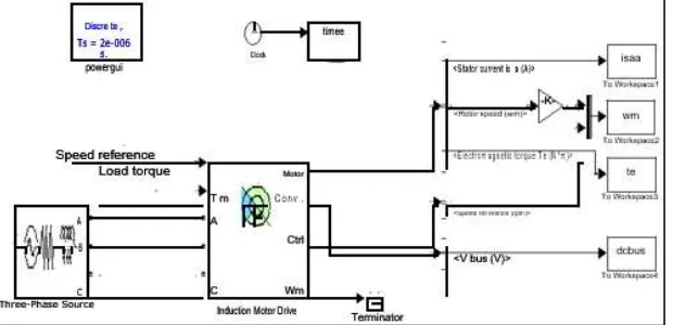
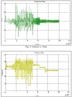
A SIMULINK block was created to analyze the open loop constant V/F control method using PI controller and the Stator current (Figure 3) and Electromagnetic torque (Figure 4) were plotted against time. The SIMULINK block is given below followed by the outcomes.
V. CLOSED LOOP V/F SPEED CONTROL METHOD USING PI CONTROLLER
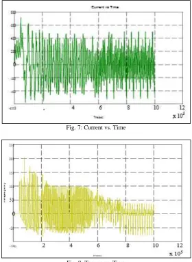
A SIMULINK block was created to analyze the close loop constant V/F control method using PI controller and the Stator current (Figure 7), and Electromagnetic torque (Figure 8) were plotted against time. The SIMULINK block is given below followed by the outcomes
Fig. 4: SIMULINK Block of Close Loop Constant V/F Speed Control using PI Controller
VI. SIMULATION RESULTS
Fig. 5: Current vs. Time
(IJIRST/ Volume 5 / Issue 5 / 004)
Fig. 7: Current vs. Time
Fig. 8: Torque vs. Time
VII.CONCLUSION
Simulation is carried out in MATLAB environment for speed control of induction motor for full load, using PI controller. And the results are checked. From the above experiment and results we concluded that the closed loop V/F control gives better response and better result as compared to open loop V/F control of induction motor.
APPENDIX
Table – 1
Machine Details used in MATLAB Codes Execution for Variable Rotor Resistance, Variable Stator Voltage and Constant V/F Control
Supply voltage (line-to-line) 415V Number of poles 4 Stator resistance 0.075 Rotor resistance(ohm) 0.1
Frequency(Hz) 50 Stator leakage reactance 0.45 Rotor leakage reactance 0.45 V/f ratio (ONLY FOR CONTANT V/F CONTROL) 8.3
REFERENCES
[1] B.K. Bose, Power Electronics and AC Drives, Prentice- Hall,’’ NJ,USA, 2002.
[2] I. Boldea, ‘‘Control issues in adjustable speed drives, ’’ IEEE Industrial Electronics Magazine, Vol. 2, No. 3, Sept. 2008, pp. 32 - 50.
[3] A. Munoz-Garcia, T.A. Lipo, D.W. Novotny, ‘‘A new induction motor V/f control method capable of high-performance regulation at low speeds, ’’ Vol. 34, No. 4, July/August 1998, pp. 813 - 821.
[5] A. Oteafy, J. Chiasson, ‘‘A Study of the Lyapunov Stability of an Open- Loop Induction Machine IEEE Transactions on Control Systems Technology,’’ Vol. 18, No. 6, Nov. 2010, pp. 1469 – 1476
[6] Wei Chen ; Dianguo Xu ; Rongfeng Yang ; Yong Yu ; Zhuang Xu ‘‘A novel stator voltage oriented V/F control method capable of high output torque at low speed,’’ International Conference on Power Electronics and Drive Systems, PEDS2009, 2-5 Nov. 2009, pp 228 - 233.
[7] C.J. Francis, H. Zelaya De La Parra, ‘‘Stator resistance voltage-drop compensation for open-loop AC drives,’’ Electric Power Applications, IEE Proceedings, Vol. 144 , No. 1, January 1997, pp.21 - 26.
[8] Y. Q. Xiang, ‘‘Instability compensation of V/Hz PWM inverter-fed induction motor drives,’’ in Conf. Rec. IEEE IAS Annu. Meeting, vol. 1, Oct. 1997, pp. 613-620.