Numerical Methods in Civil Engineering, Vol. 3, No. 1, September. 2018
Numerical Methods in Civil Engineering
In-plane effect on out-of-plane capacity of separated infill wall
A. Keyvani Borujeni*, T. Mahdi**
ARTICLE INFO Article history: Received: March 2018. Revised: July 2018. Accepted: August 2018.
Keywords: Infill,
Steel moment frame, Masonry,
Non-structural infill wall, In-plane behaviour
Abstract:
In this paper, by using a finite element model, the in-plane drift effect on the out-of-plane behavior of the infilled frame with weak infill walls has been calculated. Therefore, the out-of-plane and in-out-of-plane interaction for infill walls of different slenderness/aspect ratios, bond tension strengths and separated gap types, has been evaluated. The results are shown that infill walls having full contact at the top of the wall but isolated from columns have larger out-of-plane capacities than those isolated from beam and columns. However, infill walls having full contact at the top are more vulnerable to in-plane drifts. Also, the effect of the in-plane drift on the out-of-plane capacity of the separated infill wall can be noticeable. The results are indicated the out-of-plane capacity of the separated infill wall has been found to be inversely proportional to slenderness ratio and aspect ratio values and directly proportional to bond tension strength.
D
1. Intruduction
In recent earthquakes, serious damage of many masonry infill walls was reported. Most of the losses occurred were due to out-of-plane collapse of masonry infill walls. Thus, the main objective of the present paper is to obtain further knowledge of the out-of-plane response of masonry infill walls in order to prevent such losses. Although this kind of behavior has been investigated extensively, many areas remained vague. The correlation between the in-plane and out-of-plane infill response is one of areas that has not been fully investigated in the past.
Early methods for analyzing infill walls subjected to out-of-plane loads were generally either based on elastic methods or some type of yield line analysis. Although elastic methods are valid up to cracking, at ultimate the predominant out-of-plane resisting mechanism is arching. As the infill wall deforms after cracking, in-plane membrane forces occur in the masonry, and the infill wall exhibits an arching type of behavior.
*Corresponding Author: Assistant Professor, Young Researchers and Elite Club, Fereydan Branch, Islamic Azad University, Daran, Isfahan, IRAN, E-mail: [email protected]
**Assistant Professor, Road, Housing & Urban Development Research Center, Tehran, IRAN
The out-of-plane capacity was directly related to bond tension strength and slenderness ratio by the several references [1], [2] and [3]. Several methods were developed to compute the out-of-plane lateral capacity of masonry infill walls based on arching. Dawe et al. [4] method developed an empirical method for concrete masonry infill walls. In this method, the arching action of the wall was incorporated and varying stiffness assigned to the bounding frame. Angel et al. [5] concluded that the out-of-plane strength of the infill is affected by the slenderness ratio, the compressive strength of the infill and the reduction of the out-of-plane capacity due to in-plane displacements. Klingner et al., [6] developed the other analytical method based on two-way arching. Also, Flanagan and Bennett [7] concluded that the out-of-plane capacity is dependent on several parameters. In this paper, the out-of-plane capacity has been depended on the bond tension strength and the slenderness ratio.
In the sequential testing performed by Calvi et al. [8], the out-of-plane capacity of the infill wall was measured as a function of prior in-plane damage. Agnihotri et al. [9] studied the effect of effective parameters on in-plane and out-of-plane interaction curve. On the other hand, Dolatshahi et al. [10] evaluated the response of a masonry infill wall under different loading directions simulating various participation of the in-plane and the out-of-plane response. The out-of-plane loading was assumed to have
27
originated from the roof drifts. In addition, to show thein-plane and out-of-in-plane interaction of the wall, first, various in-plane displacements were applied at the top of the wall. Then, the out-of-plane strength reduction due to in-plane damages was determined. Other tests were carried out later by Hak et al., [11], Akhoundi et al. [12], and Furtado et al. [13]. These papers are concluded that the out-of-plane capacity of infill walls is reduced with the increase of in-plane demands. Al-Chaar [14] included these effects. More recently, Verlato et al. [15] examined two enclosures. Enclosures were first cyclically tested in the in-plane direction until 2.4% drift and then monotonically tested in the out-of-plane direction. As reference, two partial enclosures were first tested in the out-of-plane direction and then, after removal of damaged enclosures, the remaining reinforced concrete frame was tested in the in-plane direction until 3.0% drift. In recent years, this concept has been represented using strength and dis-placement interaction curves [16], [17]. These curves were determined using both experimental and numerical tests on infill walls.
In above mentioned studies, the sequence of applying the in-plane and the out-of-plane loads are different from one study to the other. In this paper, and to investigate the out-of-plane strength reduction, the infilled frame with weak infill wall has been pushed to the required in-plane displacement. Then, the out-of-plane strength of the infill wall has been measured by applying a uniform increasing pressure on the infill wall until collapse. Though the out-of-plane stability of infill walls under seismic loading is a dynamic problem, the present paper has presented this behavior in a simplistic manner by applying monotonically increasing out-of-plane pressure.
Furthermore, the effect of separating gap between the infill wall and the frame on the out-of-plane behavior of the infilled frames was investigated by different researchers [4], [18], [19], [20]. In this paper, two following alternative systems with separating gaps have been suggested in this paper:
1) A system with a complete decoupling of the infill wall from beam and columns with suitable mechanical connectors.
2) A system with full contact at the top of the infill wall and decoupled columns with suitable mechanical connectors
To have better understanding of the out-of-plane behavior of infill walls with prior in-plane damage, the out-of-plane capacity of the two systems mentioned above has been investigated to evaluate their out-of-plane capacity for varying degree of in-plane damage. This has been carried out for infilled frame with weak infill wall of different in-plane drifts, aspect ratios, bond tensile strengths, and different slenderness ratios.
Numerically, both the macro and the micro-models have been used in the past. Most authors preferred to use the
simplified macro-models rather than the more-complex micro-models because of computational limitations. This concept has been advanced by Mosalam et al. [21] by refining and implementing a previous proposal by Kadysiewski et al. [22]. Recently, Furtado et al. [23] developed a similar macro-model based on a two-diagonal infill wall model.
In Keyvani and Mahdi [32], the useful micro finite element model has been presented. In this research, the brittle cracking model has been used. This method can be used to study the out-of-plane behavior with prior in-plane damage of weak infill walls. Therefore, Keyvani and Mahdi [32] procedure has been used for this present paper.
2. Modeling concept
2.1 Overall simulation approach
The general purpose finite element program ABAQUS [24] has been used in this paper. The masonry infilled frame has been idealized by a three dimensional simulation model consists of a steel frame connected by contact elements to the masonry infill wall. The infill wall itself has been modeled using the “Simplified Micro” model
2.2 Modeling of the steel frame
The columns and beam have been modeled by using the 3D solid element (C3D8). The nonlinear material behavior of steel has been described by means of the isotropic/kinematic model which has been provided in ABAQUS [24]. This model requires the definition of stress-strain curves to be assigned with plasticity parameters. A detailed description of the plasticity parameters and their selection is given in Jia.L.J et al. [25] as following:
Table.2: Mechanical properties of steel material Equivalent Stress at First
Plastic Yield
Hardening Parameter Kinematic Isotropic
δ0 C γ Q
MPa MPa - MPa 255.9 1617.2 10.7 227.8
2.3 Modeling of the masonry infill wall
The modeling of the masonry has been carried out by using the “Simplified Micro” model, in which an explicit idealization of the mortar joints has been prevented. According to this model, the properties of the mortar and the unit/mortar interface have been lumped into a common interface element, while expanded elements have been used to represent the masonry units. These units have been modeled by homogenous solid elements (C3D8).
Based on unit type, it is accepted that a masonry unit exhibits two primary models of behavior; (1) tensile brittle behavior, (2) compressive ductile behavior [32]. The tensile brittle behavior is associated with tension fracture mechanism. In according to Keyvani and Mahdi [32], the
Numerical Methods in Civil Engineering, Vol. 3, No. 1, September. 2018 hollow blocks have the tensile brittle behavior and the
“Brittle Crack” model of ABAQUS [24] can be used. However, despite elastic behavior of compression, Keyvani and Mahdi [32] presented reliability of “Brittle Crack” model for hollow block.
The isolated gap between frame members and infill wall has been modeled by the interface element. The interface element is capable of simulating both separation and slip. When the surfaces of the frame members and infill wall are in contact, it incorporates shear resistance along its interface. There is generally a relationship between this shear resistance and normal stress on the interface. In his paper, the geometrical distance between the column/beam flange and the infill wall has been modeled according to its actual dimension.
Tensile and compression strengths of masonry units have been extensively investigated by many researchers [26], [27] and [28]. Generally, it can be stated that the tensile strength is around 10% of the compressive strength, and it is in the range of 1.5MPa–3.5MPa. On the other hand, the compressive strength of masonry units is around 10MPa–40MPa. Also, based on Moustafa [29], the elasticity module of masonry prism is between 1100MPa and 2500MPa.
In this study, based on previous experimental work [30], the tensile strength, the compressive strength and the elasticity modulus has been chosen as 1.5MPa, 15MPa and 1500MPa respectively. The mechanical properties of brittle cracking are illustrated in Table 2.
Table.3: Mechanical properties of brittle cracking model
Tensile strength Shear strength Elasticity module
ft fc E
MPa MPa MPa 1.5 15 1500
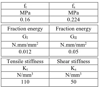
The joint between the individual units has been simulated by using interface elements (COH3D8), that enable the transmission of compressive stresses as well as tensile and adhesive shear stresses until the maximum strength is reached. Since the head joints are usually not filled with mortar, the load transfer is directly limited to the bed joints. Furthermore, after exceeding the adhesive shear stresses in the bed joints, only compressive stresses and frictional forces are transmitted between the single units. The mechanical properties of the interface elements suggested by Lourenco [31] are given in Table 3.
Table.4: Mechanical properties of interface model Tensile strength Shear strength
ft fs
MPa MPa
0.16 0.224
Fraction energy Fraction energy
GI GII
N.mm/mm2 N.mm/mm2
0.012 0.05
Tensile stiffness Shear stiffness
Kt Ks
N/mm3 N/mm3
110 50
3. Numerical modeling verification
In Keyvani and Mahdi [32], the numerical analysis of masonry infill walls has been validated against the experimental results. These experimental results have been tested at the Structural Department Laboratory of Road, Housing, and Urban Development Research Centre (BHRC), Tehran, Iran and have been reported by Keyvani and Mahdi [30]. This research has been shown approximately similar behaviors of the numerical and experimental results.
Therefore, it can be concluded that the present analysis is generally capable of simulating the behavior of the experimental infill wall. Also, it can be seen from this verification procedure that the “Brittle Cracking” (BK) model is able to capture the cracking pattern in the hollow blocks of an infill wall. Furthermore, by modeling the joints between individual units by interface elements, the compressive stresses as well as tensile and bond shear stresses between the units are reasonably represented. Generally, the finite element model developed in Keyvani and Mahdi [32] has been found effective in predicting the behavior of infill walls.
4. Numerical simulation
As discussed before, the out-of-plane capacity can be significantly reduced due to prior in-plane damage. To investigate this behavior, a finite element model has been used to generate interaction curves that depict the variation of out-of-plane capacity of weak infill wall with varying in-plane damage.
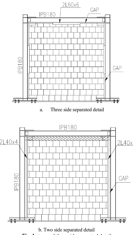
In this paper, according to Keyvani and Mahdi [32], two types of separated gap have been used. Thus, specimens can be classified into two major categories and as follows: 1) Infilled steel frames having masonry infill walls and isolated from the upper beam and columns, as shown in Figure 1.
2) Infilled steel frames having masonry infill walls that are in full contact at the top of the wall but isolated from columns, as shown in Figure 1.
In all these specimens, the frames are one-story, one-bay moment-resisting steel frames. The heights of infill walls
29
are chosen in the range of 2 to 3 m, the span is keptconstant at 3 m, and the thickness in the range of 100 to 200 mm. To have better understanding of their behaviors, different values for slenderness ratios, aspect ratios, and bond tension strengths are selected. The surrounding steel moment-resisting steel frames are selected too strong in relation to the infill wall. The properties of these specimens are shown in Tables 4 and 5.
Table. 4: Specification of specimens with 3side separated infill Cohesion Gap(mm) t L H Sample Name MPa Column Beam mm mm mm 0.16 0.10 0.07 20 20 150 3000 3000 N1 C1,C2,C3 0.16 0.10 0.07 20 20 100 3000 3000 N3 C1,C2,C3 0.16 0.10 0.07 20 20 200 3000 3000 N5 C1,C2,C3 0.16 0.10 0.07 20 20 150 3000 2000 N7 C1,C2,C3 0.16 0.10 0.07 20 20 100 3000 2000 N9 C1,C2,C3 0.16 0.10 0.07 20 20 200 3000 2000 N11 C1,C2,C3
Table. 5:Specification of specimen with 2side separated infill
a. Three side separated detail
b. Two side separated detail
Fig. 1: two and three side separated detail
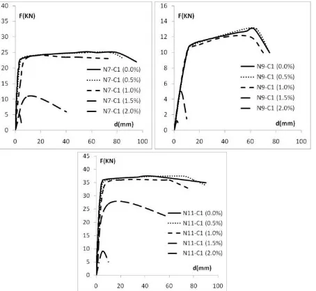
Figures 2 to 9 show the out-of-plane capacity of infill walls due to initial in-plane drifts of 0%, 0.5%, 1.0%, 1.5% and 2.0%. It is clear from these figures that the out-of-plane capacity of infill wall is reduced by the in-plane drift.
Fig. 2: The out-of-plane load-displacement curve for N1 Cohesion Gap(mm) t L H Sample Name MPa Column Beam mm mm mm 0.16 0.10 0.07 40 0 150 3000 3000 N2 C1,C2,C3 0.16 0.10 0.07 40 0 100 3000 3000 N4 C1,C2,C3 0.16 0.10 0.07 40 0 200 3000 3000 N6 C1,C2,C3 0.16 0.10 0.07 40 0 150 3000 2000 N8 C1,C2,C3 0.16 0.10 0.07 40 0 100 3000 2000 N10 C1,C2,C3 0.16 0.10 0.07 40 0 200 3000 2000 N12 C1,C2,C3
Numerical Methods in Civil Engineering, Vol. 3, No. 1, September. 2018 Fig. 3: The out-of-plane load-displacement curve for N3
Fig. 4: The out-of-plane load-displacement curve for N5
Fig. 5: The out-of-plane load-displacement curve for N7,N9,N11
Fig. 6: The out-of-plane load-displacement curve for N2
Fig. 7: The out-of-plane load-displacement curve for N4
Fig. 8: The out-of-plane load-displacement curve for N6
31
Fig. 9: The out-of-plane load-displacement curve for N8,N10,N12
For a typical infill wall subjected to in-plane and out-of-plane forces, the effect of in-out-of-plane drift on out-of-out-of-plane capacity for N1-C1 and N2-C1 is shown in Figure 10. As shown in this figure, the infill wall having full contact at the top of the wall but isolated from columns (N2-C1) has larger out-of-plane capacities than it isolated from beam and columns (N1-C1). However, infill walls having full contact at the top are more sensitive to in-plane drifts.
Fig. 10: Variation of out-of-plane capacity with in-plane drifts (N1 and N2)
The effect of in-plane drift on out-of-plane capacity for N1-C1 and N7-N1-C1 is shown in Figure 11. As shown in this figure, the two meter infill wall (N7-C1) has larger out-of-plane capacities than three meter infill wall (N1-C1).
Fig. 11: Variation of out-of-plane capacity with in-plane drifts (N1 and N7)
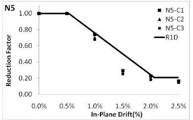
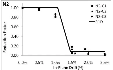
To compare the behavior at various in-plane drift levels, the out-of-plane pressure is normalized with the undamaged capacity of the wall. Thus, for each in-plane drift a corresponding out-of-plane bearing is obtained and an interaction curve is generated by plotting these values obtained for various in-plane drifts. An interaction curve obtain for the in-plane reduction factor is shown in Figures 12 to23.
Fig. 12: The reduction factor as a function of in-plane drifts (N1)
Fig. 13: The reduction factor as a function of in-plane drifts (N3)
Fig. 14: The reduction factor as a function of in-plane drifts (N5)
Fig. 15: The reduction factor as a function of in-plane drifts (N7)
Numerical Methods in Civil Engineering, Vol. 3, No. 1, September. 2018 Fig. 16: The reduction factor as a function of in-plane drifts (N9)
Fig. 17: The reduction factor as a function of in-plane drifts (N11)
Fig. 18: The reduction factor as a function of in-plane drifts (N1)
Fig. 19: The reduction factor as a function of in-plane drifts (N1)
Fig. 20: The reduction factor as a function of in-plane drifts (N1)
Fig. 21: The reduction factor as a function of in-plane drifts (N1)
Fig. 22: The reduction factor as a function of in-plane drifts (N1)
Fig. 23: The reduction factor as a function of in-plane drifts (N1)
In Figures 12 to23, the out-of-plane capacities have been normalized against the peak capacities (undamaged capacity) of the wall, i.e., the capacity of the wall at each in-plane drift is divided by the undamaged capacity of the wall. When the infill wall is subjected to in-plane loads, no reduction is observed up to the isolated gap distance. After this distance, significant reduction has been observed in the out-of-plane capacity. At higher in-plane drifts, the infill
33
wall experiences considerable damage and reached itsresidual capacity in out-of-plane direction.
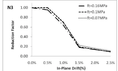
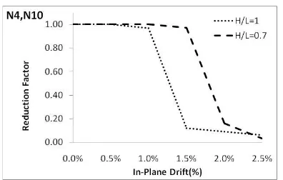
According to Figures24 to 29, this reduction factor is slightly dependent to the bond tension strength. Furthermore, Figures 30 and 31 show that slenderness ratio has little effect on the reduction factor. On other hand, Figures 32 to 37 show that aspect ratio has significant effect on the reduction factor.
Fig. 24: The reduction factor as a function of in-plane drift and bond tension strength (N1)
Fig. 25: The reduction factor as a function of in-plane drift and bond tension strength (N2)
Fig. 26: The reduction factor as a function of in-plane drift and bond tension strength (N3)
Fig. 27: The reduction factor as a function of in-plane drift and bond tension strength (N4)
Fig. 28: The reduction factor as a function of in-plane drift and bond tension strength (N5)
Fig. 29: The reduction factor as a function of in-plane drift and bond tension strength (N6)
Fig. 30: The reduction factor as a function of in-plane drift and slenderness ratio(N2,N4,N6)
Numerical Methods in Civil Engineering, Vol. 3, No. 1, September. 2018 Fig. 31: The reduction factor as a function of in-plane drift and
slenderness ratio(N1,N3,N5)
Fig. 32: The reduction factor as a function of in-plane drift and aspect ratio(N1,N7)
Fig. 33: The reduction factor as a function of in-plane drift and aspect ratio(N2,N8)
Fig. 34: The reduction factor as a function of in-plane drift and aspect ratio(N3,N9)
Fig. 35: The reduction factor as a function of in-plane drift and aspect ratio(N4,N10)
Fig. 36: The reduction factor as a function of in-plane drift and aspect ratio(N5,N11)
Fig. 37: The reduction factor as a function of in-plane drift and aspect ratio(N6,N12)
5. Conclusions
The out-of-plane behavior of separated infill walls with prior in-plane drift has been investigated using FE analysis. In this paper, infill walls with isolated gaps have been used inside the frames. In dealing with the out-of-plane resistance of infill walls, those having full contact at the top but isolated from columns have shown higher capacities than those isolated from beam and columns. The correlation between the in-plane and out-of-plane loadings has been investigated. Interaction curves were generated for out-of-plane capacity of separated infill walls subjected to various in-plane damage levels. Significant effect of the in-plane drift has been observed on the out-of-plane capacity of the separated infill wall and such effect can be quite noticeable when severe in-plane drift has occurred. In such cases, the out-of-plane capacity can be reduced to about one-fifth of its undamaged capacity.
35
The out-of-plane capacity of the separated infill wall hasbeen found to be inversely proportional to slenderness ratio and aspect ratio values and directly proportional to bond tension strength. Furthermore, the maximum reduction in the out-of- plane capacity of cracked infill walls has been found to be dependent on the slenderness ratio and the type of the isolated gap
References
[1] Drysdale, R.G., and A.S. Essawy, (1988). Out-of-Plane Bending of Concrete Block Walls. Journalof the Structural Division, American Society of Civil Engineers, Vol. 114, No.
[2] Haseltine, B., Vest, H.W.H., and Tutt, J. N.,(1977), “Design of Walls to Resist Lateral Loads”, The Structural Engineers, Pt 2, Vol. 55, No. 10, pp 422-430.STl, pp. 121-133.
[3] Hendry, A. W. and A. M. A. Kheir, (1976). The Lateral Strength of Certain Brickwork Panels, Proceedings of the Fourth International Brick Masonry Conference; l. Brugge, Belgium, pp. 4.a..3.1-4.a.3.4.
[4] Dawe, J. L. and C. K. Seah, (1989), "Out-of-plane resistance of concrete masonry infilled panels." Canadian Journal of Civil Engineering 16(6): 854-864.
[5] Angel, R., Abrams, D. P.,(1994), ‘‘out of plane strength evaluation of URM infill panels’’ NCEER-94- 0004
[6] Klingner R. E., Rubiano N. R., Bashandy T. R., and Sweeney S. C. (1996), ‘‘Evaluation and analytical verification of shaking table data from infilled frames. Part 2: Out of plane behavior.’’ Proc., 7th North Am. Masonry Conf., 521–532.
[7] Flanagan RD, Bennett RM. , (1999), “Bidirectional behavior of structural clay tile infilled frames”. J Struct Eng;125(3):236– 44.
[8] Calvi, G.M., Bolognini D., (2001), “Seismic response of RC frames infilled with weakly reinforced masonry panels”, Journal of Earthquake Engineering, 5(2), 153-185.
[9] Agnihotri P., Singhal V., Rai D. C.,(2013), ”Effect of in-plane damage on out-of-plane strength of unreinforced masonry walls”, Dept. of Civil Engineering, Indian Institute of Technology Kanpur, Kanpur, UP 208016, India
[10] Dolatshahi K. Maref., A. J., Yekrangnia M., (2014), "Bidirectional Behavior of Unreinforced Masonry Walls, Earthquake Engineering & Structural Dynamics, Published Online In Wiley Online, Doi: 10.1002/Eqe.2455
[11] Hak S., Morandi P., Magenes G.,(2014), “Out-of-plane experimental response of strong masonry infills”, second europian conference on earthquake engineering and seismology
[12] Akhoundi, F. et al., (2015), “In-plane and out-of-plane experimental characterization of RC masonry infilled frames”. In J.F.S. Gomes & S.A. Meguid, eds. Proceedings of the 6th International Conference on Mechanics and Materials in Design. Ponta Delgada, pp.427–440.
[13] Furtado, A., Rodrigues, H., Arêde, A., and Varum, H. (2016). Experimental eval-uation of out-of-plane capacity of masonry infill walls. Eng. Struct. 111, 48–63. doi:10.1016/j.engstruct.2015.12.013
[14] AL-Chaar, G., ISSA, M. and Sweeney S.,(2002) "Behavior of masonry- infilled no ductile reinforced concrete frames", J. of Struct. Eng., 128(8), pp. 1055-1063.
[15] Verlato N., Guidi G., da Porto F. and Modena C. (2016), “Experimental testing and numerical modelling of infill masonry walls subjected to in-plane damage”, 9th International Masonry Conference, University of Minho & IMS
[16] Maheri, M. R., Najafgholipour, M. A., Rajabi, A. R.,(2011), “The influence of mortar head joints on the in-plane and out of plane seismic strength of brick masonry walls”, Iranian J. Science and Technology, 2011; 35: 63-79.
[17] Najafgholipour, M.A., Maheri, M.R., Lourenço, P.B., (2013), “Capacity interaction in brick masonry under simultaneous in-plane shear and out-of-in-plane bending loads”, Construction and Building Materials, 2013; 38: 619-626.
[18] Dafnis, A., H. Kolsch and H. Reimerdes, (2002), "Arching in Masonry Walls Subjected to Earthquake Motions." Journal of Structural Engineering 128(2): 153-159.
[19] Dazio, A., (2008), Effect of boundary conditions on the out-of-plane behavior of unreinforced masonry walls. 14th World Conference on Earthquake Engineering. Beijing, China.
[20] Tu, Y.-H., T.-H. Chuang, P.-M. Liu and Y.-S. Yang ,(2010), "Out-of-plane shaking table tests on unreinforced masonry panels in RC frames." Engineering Structures 32(12): 3925-3935.
[21] Mosalam, K.M. and S. Günay, (2015), “Progressive Collapse Analysis of RC Frames with URM Infill Walls Considering In-Plane/Out-of-Plane Interaction,” Earthquake Spectra, May 2015, Vol. 31, No. 2, pp. 921-943 [Featured on the cover of the journal issue].
[22] Kadysiewski, S. and K.M. Mosalam, (2009), “Modelling of Unreinforced Masonry Infill Walls Considering In-Plane and Out-of-Plane Interaction,” Proceedings of the 11th Canadian Masonry Symposium, May 31-June 3, 2009, Toronto, Ontario, Canada, 10 pp.
[23] Furtado, A., Rodrigues, H., Arede, A., and Varum, H. (2015). Simplified macro-model for infill masonry walls considering the out-of-plane behaviour. Earthq. Eng. Struct. Dyn. 45, 507–524. doi:10.1002/eqe.2663
[24] Simulia (2014)a. Abaqus FEA. Providence: Dassault Sys-tèmes Simulia Corporation.
[25] Jia.L.J & Kuwamura H.(2014), “Prediction of Cyclic of Mild Steel at Large Plastic Strain Using Coupon Test Results”, journal of structural engineering,140(2)
[26] Stavridis, A. & Shing., P.B. 2009, “Finite Element Modeling of Nonlinear Behavior of Masonry-Infilled RC Frames”. In, Journal of Structural Engineering 136(3): 285–296.
[27] Crisafulli F. J., (1997), "Seismic behaviour of reinforced concrete structure with masonry infill", A thesis for doctor of philosophy, department of civil engineering, university of Canterbury, New Zealand
[28] Van Der Pluijm, R. (1992). “Material properties of masonry and its components under tension and shear.” 6th Canadian Masonry Symposium. Saskatchewan Canada, 675-686.
[29] Abbas Moustafa, (2012), Earthquake-Resistant Structures– Design, Assessment And Rehabilitation, Published by InTech Janeza Trdine 9, 51000 Rijeka, Croatia
[30] Keyvani, A. and Mahdi T., (2017), “Reducing the In-plane Effect of Infill on Steel Moment Frame”, International Journal of Steel Structures, September 30
[31] Lourenco, P.B. (1996). “Computational strategies for masonry structures”. PhD diss., TU Delft, Delft University of Technology.
[32] Keyvani, A. and Mahdi T., (2017), “Nonlinear Modeling of the Infill Wall Based on the Brittle Cracking Model”, Numerical Methods in Civil Engineering, Jun 30