Vol.7 (2017) No. 3
ISSN: 2088-5334
Simulation of Wickless-Heat Pipe as Passive Cooling System in
Nuclear Spent Fuel Pool Using RELAP5/MOD3.2
Mukhsinun Hadi Kusuma
#*, Nandy Putra
#, Sri Ismarwanti
#*, SuripWidodo
*#
Heat Transfer Laboratory, Department of Mechanical Engineering, Universitas Indonesia, Kampus UI, Depok, 16424, Indonesia E-mail: [email protected]
*Centre for Nuclear Reactor Safety and Technology, National Nuclear Energy Agency of Indonesia (BATAN)
E-mail: [email protected]
Abstract
—
The lesson learned from the severe accident of Fukushima Daiichi nuclear power plant shows that the residual heat generated from nuclear spent fuel should be cooled properly. In order to absorb that residual heat when station blackout occurs, the wickless-heat pipe is proposed to be used as an alternative to the passive cooling system in nuclear spent fuel pool. The objective of this research is to simulation the effect of initial pressure and evaporator filling ratio as factors that influence the thermal performance of wickless-heat pipe. The simulation results will be validated with experiment results. The wickless-heat pipe model was built and simulated using nuclear thermal-hydraulic code RELAP5/MOD3.2. The wickless-heat pipe model is built similarly, and it has same geometry with experiment test section. In the simulation, the initial pressure inside the wickless-heat pipe and evaporator filling ratio are varied. The initial pressure is varied on -54 cm Hg, -64 cm Hg, and -74 cm Hg, and filling ratio of the evaporator is varied on 40%, 60%, and 80%. The heat load of the evaporator, coolant temperature, and coolant volumetric flow rate were kept constant. The results obtained show that thermal resistance of wickless-heat pipe simulation model is 0.005°C/W. It is showed that simulation model results have good agreement with experiment results, and it can be used to simulate wickless-heat pipe heat transfer phenomena with different values of the input parameter. The RELAP5/MOD3.2 simulation model has been verified by the experimental result of a steady state condition.Keywords— wickless-heat pipe; RELAP5/MOD3.2; nuclear spent fuel pool
I. INTRODUCTION
Population growth, economic and industrial development activity is resulting in increased energy consumption required, while the sources of energy in the world is now diminishing and virtually no increase in numbers. Indonesia diminishing energy sources require different options to optimize the use of available energy reserves. The strategic step of energy usage could be done by enhancing the role of new and renewable energy sources, conserve energy, energy savings, and develop new effective technology based on thermal energy conversion [1], [2]. Because the amount of energy that is barely sufficient to meet these needs, the use of alternative energy such as nuclear energy becomes one of the options in order to achieve energy needs. Indonesia government has established a national policy of nuclear energy utilization in the future. Based on Indonesian Government Regulation No. 79/2014 on national energy policy, the use of new energy sources (including nuclear energy) and other renewable energy at least 23% in 2025 and
at least 31% in 2050 [3]. It is expected with the use of nuclear energy through nuclear power plants became a solution to overcome the shortage of energy resources. The use of nuclear technology in addition to bringing benefits, it also has the potential hazards. One of the potential hazards that would occur in the use of nuclear power plants is the release of radioactive gas in case of accidents and failures in its operation. This can adversely affect the plant workers and the public at large.
Fukushima Daiichi nuclear power plant severe accident is caused by station blackout following unprecedented earthquake and tsunami. The severe accident resulted in four reactor buildings melted, one of them is nuclear spent fuel pool building. The amount of residual heat that was generated could not be properly cooled because no electrical power was available to operate the cooling system due to a malfunction of the redundant electric generator when the loss of electric power occurred. The melted of nuclear spent fuel pool due to the accumulation of heat in the building. This heat would otherwise be absorbed by the cooling water that circulated in the storage pool, but in the absence of electricity supply as a result of station blackout resulting heat cannot be wasted perfectly into the environment. The heat reacts with hydrogen gas production resulting in the nuclear spent fuel pool building pressure exceeds its critical pressure.
A severe accident at Fukushima Daiichi nuclear power plant has become a lesson to learn to improve the design of nuclear safety technology in the world. Based on station blackout event, the passive cooling method is beginning to observe for use as an alternative cooling system on the reactor system when the active cooling system is stopped operating. Although it has a cooling capacity slower than the active system, the passive cooling system can be expected to help remove the heat generated until the active system can operate as before.
A passive cooling system as passive residual heat removal system has been studied by many researchers. One of passive cooling system method used for removing the residual heat is heat pipe technology. The heat pipe is an effective technology that uses a certain size pipe with filled fluid as a conductor of heat from the evaporator to the condenser. The heat pipe can transport large amounts of heat with a small temperature difference, working in two phases; its operation does not require any additional external driving source such as an electric source, batteries, pumps, and others (i.e., it is a passive system) [4, 5]. Reference [5-7] have conducted many investigations on a passive cooling system using heat pipes. They investigation results show that heat pipes can be used as a very good medium to transfer heat from heat source to heat sink [6-9].
Especially in the nuclear field, many researchers have also done the investigations of the use of heat pipes as a passive cooling system. Reference [10] have investigated the performance of two-phase thermosyphon (wickless-heat pipe) that uses phase change heat transfer material alkali metal for the next generation nuclear reactor. Their results showed that the thermosyphon had a great performance to be used as passive heat removal system in next generation of nuclear reactor [10]. Reference [11] have investigated experimentally the using of the thermosyphon type heat pipe as a passive cooling system on nuclear spent fuel storage pool. Their result showed that thermosyphon type heat pipe
had sufficient capacity to maintain the temperature of reactor pressure vessel and keep its safe during an accident [11].
Reference [12] have conducted both simulation and experiment of the using of two-phase thermosyphon loop in China nuclear reactor spent fuel storage pool. ANSYS FLUENT software and RELAP 5/MOD3.2 code were used as a simulation tool to study the effect of filling ratio on the
thermosyphon thermal performance. Experiments have also done to compare the results of numerical simulation. Their result shows that two-phase thermosyphon loop had a good heat transfer performance when it operated on its filling ratio of 30% - 80% and it could remove a large amount of heat from spent fuel storage pool [12]. Reference [13] have conducted experimental research on the use of loop heat pipe as a passive cooling system in reactor spent fuel pool. The experimental apparatus with loop heat pipe high of 8.2 m and rising tubes of 0.72 m. Hot water was used as evaporator heat source. The spent fuel pool temperature was set at 60°C. Loop heat pipe used R-134a working fluid and air was used as cooling media to absorb the heat in the condenser section. Their result shows that the loop heat pipe has the good thermal performance to be used as a passive cooling system in nuclear reactor spent fuel pool [13].
Other researchers investigated the performance of thermosyphon as a passive cooling system with varied of material properties, dimensions, aspect ratio, working fluid, evaporator filling ratios, coolant mass flow rates, evaporator heat loads, initial pressures, and inclination angles. Their results showed that the thermosyphon had a good performance to remove the heat to the ultimate heat sink [14]-[18].
Many researchers have also carried out the investigations of characteristics of heat pipes as passive cooling technology method. Reference [19] have investigated the effect of aspect ratio and the filling ratio of two-phase closed thermosyphon thermal performance. The experiment was performed by varying the evaporator filling ratio from 20% to 60%, the aspect ratio of 15, 20, and 30, and inclination angle from 15° to 90°. The thermosyphon was used a copper material with an inner diameter of 14 mm, an outer diameter of 16 mm and length of 1000 mm. Distilled water was used as the working fluid. Their results show that the best thermal performance of thermosyphon was obtained when it is operated at an inclination angle of 60° and a filling ratio of 45%. The highest condensation heat transfer coefficient to the aspect ratio is at an inclination angle of 30°- 45°[19]. Experiment investigation of thermosiphon was conducted [17] to determine the thermosiphon heat transfer characteristics. The thermosyphon was made of Cu and used the working fluid of FC-72 (C6F14). The evaporator filling
ratio and heat load were varied from 10%- 70% and 50-600 W, respectively. Their result shows that the heat transfer coefficient in the evaporator is hardly influenced by filling ratio. Heat transfer coefficient was increased with the increase of filling ratio [17].
section has a length of 2 m, the adiabatic section has a length of 2 m, and condenser section has a length of 2 m. The effect of evaporator heat flux and air velocity is studied to know its heat transfer characteristics and thermal performance. The obtained results showed that natural circulation on the wickless-heat pipe could be achieved rapidly when higher heat flux and sufficient air velocity is given to wickless-heat pipe [20]. The experiment and simulation investigation were also conducted in order to know the wickless-heat pipe characteristics. A small scale of vertical straight wickless-heat pipe with water coolant system is set as a prototype model of the large scale of vertical straight wickless-heat pipe that will be applied in the Indonesia research reactor spent fuel pool. The small scale of wickless-heat pipe has a length of 1.5 m and the inner diameter of 0.0254 m. Each of evaporator, adiabatic, and condenser section has 0.5 m on length. The condenser is covered with water jacket. Circulating thermostatic bath is used to control the constant temperature and mass flow rate of water coolant in the water jacket. Effect of evaporator filling ratio, initial pressure, heat load, and mass flow rate are investigated. To support the experiment investigation, a small scale of wickless-heat pipe simulation model using RELAP5/MOD3.2 is also investigated. The results showed that small scale of wickless-heat pipe had the best thermal performance when it operated at filling ratio of 60%, lower initial pressure, higher head load, and higher mass flow rate. The simulation heat pipe model is also validated with experiment results. The heat pipe simulation model results in similar phenomena with experiment phenomena, and it can be used to predict the phenomena inside heat pipe [21].
From previous investigations, it is known that the simulation using RELAP5/MOD3.2 for the large scale of vertical straight wickless-heat pipe with water coolant is rarely studied. This simulation is used as a supporting tool for analysing the experiment investigation of vertical straight wickless-heat pipe as an alternative of a passive cooling system that can be applied in spent fuel pool. The objective is to know the effect of initial pressure and filling ratio as factors that influence the wickless-heat pipe thermal performance. In this simulation, initial pressure and filling ratio of wickless-heat pipe are used as varied parameters that influence the thermal performance of wickless-heat pipe. The simulation model results will be then validated with experiment results.
II. MATERIAL AND METHOD
A. Experimental Setup
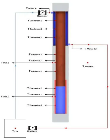
The experimental setup and experiment test section can be seen in Fig. 1. the vertical straight wickless-heat pipe is made of a copper tube with 6 m of length, an inner diameter of 0.1016 m, and an outer diameter of 0.1031 m. The wickless-heat pipe is divided into three parts with the same length of aspect ratio: evaporator section has a length of 2 m, the adiabatic section has a length of 2 m, and condenser section has a length of 2 m.
The evaporator section is located at the bottom section, the adiabatic section is located at the middle section, and the condenser is located in the top section. The whole wickless-heat pipe is isolated by using glass wool and an aluminium
sheet in order to reduce the heat lost from the heat pipe system. The evaporator section is belted with electric band heater with maximal heat generation of 2800 W. Band heater is assumed as heat generation from nuclear spent fuel pool. An analogue voltage regulator is used to control the heat load for the evaporator. The evaporator is also used as working fluid pool. De-mineral water was selected as heat pipe working fluid. Filling ratio of the evaporator is varied.
The water jacket is used as a heat absorber and installed covering the condenser section. The water jacket is connected to circulating thermostatic bath. Thermostatic bath is used as water coolant source and kept the coolant temperature, and mass flow rate is constant. In the experiment, the mass flow rate was varied. The mass flow rate was observed by using a manual flowmeter, and the circulating thermostatic bath temperature is controlled by using AUTONICS with the accuracy of ±2°C.
Fig.1 Experimental setup
Fig. 2 Thermocouple placement on the wickless-heat pipe
B. Simulation Model
A model to simulate the wickless-heat pipe as a passive cooling system in nuclear spent fuel pool was built using thermal-hydraulics code RELAP5/MOD3.2. The
nodalization model of the wickless-heat pipe can be seen in Fig. 3.
The Pipe P001 represents the steam line in the evaporator section, P002 represents the steam line in the adiabatic section, and P003 represents the steam line at the condenser section. Pipe P101 represents the condensate line in the evaporator section, P102 represents the condensate line in the adiabatic section, and P103 represents the condensate line in the condenser section.
Single junction model is used to connect between pipe. Single junction SJ01 is used to connect evaporator and adiabatic steam line, SJ02 is used to connect adiabatic and condenser steam line, SJ03 is used to connect evaporator and adiabatic condensate line, and SJ04 is used to connect adiabatic and condenser condensate line. Single junction SJ05 is used to connect whole heat pipe with a water jacket, and SJ06 is used to connect water jacket with circulating thermostatic bath.
Time-dependent volume TDV00 is used as a water jacket, and TDV01 is used as circulating thermostatic bath.
Time-dependent junction TDJ was used as a junction that connects the water jacket and the circulating thermostatic bath. Heat structure HS000 is used to simulate the model of heat transfer between the cooling water in the water jacket and the condenser section, and HS001 is used to simulate the model of heat transfer between the electric band heater and an evaporator section.
Fig. 3 Nodalization model of wickless-heat pipe simulation
To achieve a better result of the simulation, each section of the heat pipe is divided into 10 nodes. The steam line of evaporator, adiabatic, and condenser section are divided into
In this simulation, the effect of initial pressure and filling ratio were analyzed; with a constant value of heat load, coolant temperature and mass flow rate.
The initial pressure inside heat pipe is varied for -54 cm Hg, -64 cm Hg, and -74 cm Hg. The working fluid is charged inside heat pipe with filling ratio of 40%, 60%, and 80%.
The constant value is kept for heat load, coolant temperature, and mass flow rate. Heat load is kept constant at 1000 W, coolant temperature of 26°C, and coolant mass flow rate of 4 L/min.
The boundary condition of wickless-heat pipe simulation is described below.
• Heat pipe dimension:
Inner diameter (r2) : 0.10374 m
Outer diamater (r1) : 0.10674 m
Inner pipe flow area : 4/5*phi*r1 = 0.006764678 m2
Outer pipe flow area : 1/5*phi*r2 = 0.001681169 m2
Inner hydraulic diameter (Dhin) : 4*A/P = (4*phi*
r2)/(2*phi *r1) = 0.092787877 m
Outer hydraulic diameter (Dhout) : 2 * rout= 0.10374 m
Dhannulus = Dhout – Dhin= 0.010952123 m
Total length : 6 m
Evaporator length : 2 m
Adiabatic length : 2 m
Condenser length : 2 m
• Water Jacket dimension: Inner diameter : 0.1524 m
Flow area : Flow area total – flow area heat pipe
: phi * r2 – 0.006764678 m2
: 0.011484133 m2
Hydraulic diameter : Dhout - Dhin
: 0.04866 m
• Water Jacket hose:
Inner diameter : 0.01905 m
Flow area : phi * r2= 0.000285138 m2
III.RESULTS AND DISCUSSION
A. Steady-State Temperature Distribution
After simulation conducted, the steady temperature distribution data is then analyzed. The steady state temperature distribution, for varied of initial pressure, filling ratio of 60%, and heat load of 1000 W, is shown in Fig. 4. The simulation result of the steady state temperature profile along the heat pipe wall was displayed in Fig. 4. It was set at varied initial pressure of -54 cm Hg, -64 cm Hg, and -74 cm Hg, filling ratio of 60%, and heat load of 1000 W. It can be seen that the lower temperature difference between evaporator and condenser is achieved when simulation of heat pipe model was conducted at the initial pressure of -74 cm Hg.
As well known, the lower different temperature between evaporator and condenser will result in the lower thermal
resistance of wickless-heat pipe. The lower thermal resistance obtained means the best thermal performance of the wickless-heat pipe. The thermal resistance formula is described below:
R = ΔT/Q (1)
Fig. 4 Simulation results of steady state temperature at various initial pressures for filling ratio of 60%
Where R is defined as the thermal resistance of the wickless-heat pipe (°C/W), ΔT is the temperature different between evaporator and condenser (°C), and Q is heat load given to evaporator section (W).
It can be seen from Fig. 4, for the constant heat load of 1000 W, the lower thermal resistance of wickless-heat pipe is obtained by simulation of filling ratio of 60% and the lower initial pressure of -74 cm Hg.
Based on above simulation, the next simulation is conducted with a variation of filling ratio of 40%, 60%, and 80% for the initial pressure of -74 cm Hg.
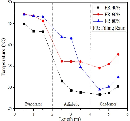
In Fig. 5, it shows the steady state temperature distribution along wickless-heat pipe for simulation of the varied filling ratio of 40%, 60%, and 80%, initial pressure of -74 cm Hg, and heat load of 1000 W.
It can be seen from Fig. 5 that the smallest temperature difference is obtained at a filling ratio of 60%. This phenomenon shows that the lower thermal resistance is achieved when wickless-heat pipe is operated at filling ratio of 60%, and initial pressure of -74 cm Hg.
To justify that the simulation results is supporting the experiment or not, the simulation results then compared with experiment results. The comparison of the heat pipe wall steady state temperature between simulation and experiment at a filling ratio of 60%, a heat load of 1000 W, a coolant volumetric flow rate of 4 L/min, and an initial pressure of -74 cm Hg is shown in Fig. 6.
Fig. 6 The comparison of heat pipe steady state temperature between simulation and experiment at filling ratio of 80%, and initial pressure of -74 cm Hg
From Fig. 6, it can be seen that the temperature distribution of simulation has similar trend line with experiment results. There was temperature deviation between simulation and experiment results because it was very difficult to make the same situation between it, such as the adiabatic condition and the value of initial pressure. In the simulation, it is very easy to make perfect conditions, but it is difficult to make perfect conditions for the experiment.
B. Thermal Performance
The simulation result of the thermal resistance of the wickless-heat pipe at various initial pressures and filling ratio were shown in Fig. 7 and Fig. 8. As seen in Fig. 7, the thermal resistances obtained from the simulation at the variation of initial pressure of 54 cm Hg, 64 cm Hg, and -74 cm Hg filling ratio of 60%, and heat load of 1000 W.
It can be seen from Fig. 7 that the lowest thermal resistances obtained when the initial pressure of wickless-heat pipe is -74 cm Hg. The reason is that the lower of initial pressure will lower the fluid saturation temperature. Lower of initial pressure will also decrease the amount of non-condensable gas that accumulates near the inner wall of the condenser section. The higher amount of non-condensable gas will hamper the condenser cooling process.
Fig. 7 Wickless-heat pipe thermal resistances at simulation with various initial pressure
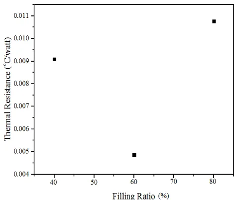
In Fig. 8, it is shown that the thermal resistances obtained when wickless-heat pipe is operated at a varied filling ratio of 40%, 60%, and 80%.It can be seen that the boiling process at filling ratio of 60% is produced stable steam and evaporation rate than other filling ratios on this simulation.
Fig. 8 Wickless-heat pipe thermal resistances at simulation with various filling ratio
IV.CONCLUSIONS
ACKNOWLEDGMENT
This research is financially supported by HIBAH KLASTER, University of Indonesia 2015. The authors would also like to thank Dr. Anhar Riza Antariksawan for the discussion concerning the RELAP5/MOD3.2 code.
REFERENCES
[1] K. Siregar, "Strategy to Reduce GHG Emission and Energy Consumption at Process Production of Biodiesel Using Catalyst From Crude Palm Oil (CPO) and Crude Jatropha Curcas Oil (CJCO) in Indonesia," International Journal on Advanced Science, Engineering and Information Technology, vol. 5, pp. 293-299, 2015. [2] P. Putera, S. A. Novita, I. Laksmana, M. I. Hamid, and S. Syafii,
"Development and Evaluation of Solar-Powered Instrument for Hydroponic System in Limapuluh Kota, Indonesia," International Journal on Advanced Science, Engineering and Information Technology, vol. 5, pp. 284-288, 2015.
[3] Presiden Republik Indonesia, "Peraturan Presiden Republik Indonesia Nomor 5 Tahun 2006 Tentang Kebijakan Energi Nasional," 2006.
[4] S. Noie, "Heat transfer characteristics of a two-phase closed thermosyphon," Applied Thermal Engineering, vol. 25, pp. 495-506, 2005.
[5] N. Putra; and W. N. Septiadi; Teknologi Pipa Kalor: Teori, Desain dan Aplikasi: Penerbit Universitas Indonesia (UI-Press), 2014. [6] N. Putra, W. N. Septiadi, H. Rahman, and R. Irwansyah, "Thermal
performance of screen mesh wick heat pipes with nanofluids," Experimental thermal and fluid science, vol. 40, pp. 10-17, 2012. [7] N. Putra, W. N. Septiadi, R. Sahmura, and C. T. Anggara,
"Application of Al2O3 Nanofluid on Sintered Copper-Powder Vapor Chamber for Electronic Cooling," Advanced Materials Research, vol. 789, pp. 423-428, 2013.
[8] N. Putra, W. N. Septiadi, R. Saleh, R. A. Koestoer, and S. Purbo Prakoso, "The Effect of CuO-Water Nanofluid and Biomaterial Wick on Loop Heat Pipe Performance," Advanced Materials Research, vol. 875, pp. 356-361, 2014.
[9] N. Putra, R. Saleh, W. N. Septiadi, A. Okta, and Z. Hamid, "Thermal performance of biomaterial wick loop heat pipes with water-base Al2O3 nanofluids," International Journal of Thermal Sciences, vol. 76, p. 8, 2014.
[10] P. Sabharwall, M. Patterson, V. Utgikar, and F. Gunnerson, "Phase change heat transfer device for process heat applications," Nuclear Engineering and Design, vol. 240, pp. 2409-2414, 2010.
[11] K. Ohashi, H. Hayakawa, M. Yamada, T. Hayashi, and T. Ishii, "Preliminary study on the application of the heat pipe to the passive decay heat removal system of the modular HTR," Progress in Nuclear Energy, vol. 32, pp. 587-594, // 1998.
[12] W. Fu, X. Li, X. Wu, and Z. Zhang, "Investigation of a long term passive cooling system using two-phase thermosyphon loops for the nuclear reactor spent fuel pool," Annals of Nuclear Energy, vol. 85, pp. 346-356, 2015.
[13] Z. Xiong, M. Wang, H. Gu, and C. Ye, "Experimental study on heat pipe heat removal capacity for passive cooling of spent fuel pool," Annals of Nuclear Energy, vol. 83, pp. 258-263, 2015.
[14] S. Noie, S. Z. Heris, M. Kahani, and S. Nowee, "Heat transfer enhancement using Al 2 O 3/water nanofluid in a two-phase closed thermosyphon," International Journal of Heat and Fluid Flow, vol. 30, pp. 700-705, 2009.
[15] T. Sukchana and C. Jaiboonma, "Effect of Filling Ratios and Adiabatic Length on Thermal Efficiency of Long Heat Pipe Filled with R-134a," Energy Procedia, vol. 34, pp. 298-306, 2013. [16] H. Imura, K. Sasaguchi, H. Kozai, and S. Numata, "Critical heat flux
in a closed two-phase thermosyphon," International journal of Heat and mass transfer, vol. 26, pp. 1181-1188, 1983.
[17] H. K. K. Yong Joo Park, Chul Ju Kim "Heat transfer characteristics of a two-phase closed thermosyphon to the fill charge ratio," International Journal of Heat and Mass Transfer vol. 45, pp. 4655– 4661, 2002.
[18] L. M. Q. B. Jiao, X.B. Zhang, Y. Zhang, "Investigation on the effect of filling ratio on the steady state heat transfer performance of a vertical two phase closed thermosyphon 2008 " Applied Thermal Engineering, vol. 28, p. 9, 2007.
[19] S. H. N. M.R. Sarmasti Emami, M. Khoshnoodi, "Effect of Aspect Ratio and Filling Ratio on Thermal Performance of an Inclined Two-Phase Closed Thermoshypon," Iranian Journal of Science and Technology, Transaction B, Engineering, vol. 32, p. 13
[20] M. H. Kusuma, N. Putra, S. Widodo, and A. R. Antariksawan, "Simulation of Heat Flux Effect in Straight Heat Pipe as Passive Residual Heat Removal System in Light Water Reactor using RELAP5 Mod 3.2," Applied Mechanics and Materials, vol. 819, p. 4, 2016.