Available Online at www.ijpret.com 249
INTERNATIONAL JOURNAL OF PURE AND
APPLIED RESEARCH IN ENGINEERING AND
TECHNOLOGY
A PATH FOR HORIZING YOUR INNOVATIVE WORK
DIGITAL CAUTION BOARD IN LOCO
A. CHAKRI1, M. JANARDHANRAJU2 1.M Tech Student, Department of E.C.E, SIETK, Puttur, Andhra Pradesh, India,
2.Associate Professor, Department of E.C.E, SIETK, Puttur, Andhra Pradesh, India,
Accepted Date: 24/07/2015; Published Date: 01/08/2015
\
Abstract: - In present days, railways is providing a hard copy to the loco pilot which consists of speed limit’s he should maintain at different distances .According to the information, the loco pilot follows the particular speeds at that distance. As there are some limitations regarding maintenance of hard copy .If it is lost or damaged the loco pilot has a chance of misleading the train with different speeds resulting in accidents. So, by this project, the speeds are indicated which should maintain continuously at different distance without fail. The speeds vary from one area to another area and the caution boards indicate this information .The trains may not maintain the speed at specified areas, due to its momentum or the driver’s overlook leading to train accidents. The loco pilot has to maintain the speeds as per the caution orders in caution paper. If the signal is not visible to the loco pilot because of any fog or smoke. Then there is a chance of accidents. To avoid such incidents, the proposed idea is “digital caution board” .The distance travelled by the train is noted and when the train crosses a particular distance, a message is indicated to the driver on the LCD provided. This is driven by a microcontroller.
Keywords:Caution paper, LCD, Microcontroller.
Corresponding Author: MR. A. CHAKRI
Access Online On:
www.ijpret.com
How to Cite This Article:
A Chakri, IJPRET, 2015; Volume 3 (12): 249-256
Available Online at www.ijpret.com 250 INTRODUCTION
Transportation became a major requirement in present days. People are eager to choose the cheapest and safest way to reach their destination. Fortunately there is a dominant choice the railways. People choose railways for the transportation of the goods of heavy weight which is hard to transport by roadways. Carrying heavy load may lead to accident and losing the material which could so essential. Also the cost of transporting the goods of heavy mass may be highly economical. So people choose the alternate way the railways.
Railways were introduced to India in 16th April 1853 from Mumbai to thane. In 1951 the
systems were nationalized as unit Indian railways. The net income for government from railways is around Rs.157.8 billion. Railways are available for the services like passenger railways freight services, parcel carrier and tourism services, domestic transportation etc.
It’s the duty of the railway department to ensure safe journey as desired by the people. A loco pilot has proper training to drive the loco without committing to any accident. His major activity is controlling the speed of train according to the distance and condition. The way to vary the speed is by using the notches (gears). These notches reduces the number of revolutions per minute (RPM) of the loco wheel. There by reduces the speed.
2. EXISTING METHOD
In the existing system the loco pilot was provided the cautions my means of a sheet of paper. According to the distance and corresponding speed mentioned in the paper he has to control the speed of the train. The speed limit should be not exceeded by the loco pilot manually. The distance should be observed by the railway pole or particular railway station taking it as a landmark.
It is difficult to maintain the sheet of paper besides driving the loco. The paper may become wet, tare, lost etc. It will become so difficult to observe the landmark under the conditions like fog, haze. So then it will become overhead to the loco pilot and he is forced to take his own decision to go with particular speed to ensure safety.
Available Online at www.ijpret.com 251 3. PROPOSED METHOD
In the existing system the maintenance of sheet of cautions is the main area where the proposed system is focused on. The paper was replaced by the caution board. The caution board comprises the PIC microcontroller. The permanent cautions are written inside the memory of microcontroller. According to the distance the microcontroller chooses and provides the speeds to the LCD display provided to assist the loco pilot. Loco pilot thereby could change the speed accordingly.
The distance is noted by using the infrared transmitter and receiver set in line of sight at the wheel of the loco. Based on the number of revolutions the distance is estimated and speed is suggested.
When the emergency situations occurs like natural calamity, wreck of trees and rail cracks the gang man or line man has to take the charge and inform to the regional station to transmit the emergency signal. Another way is to put an RF receiver at the area of defect and activate it. It alerts the trains entering its proximity.
4. WORKING
This project consists of a PIC microcontroller in the caution board section interfaced to an LCD display, who displays the speeds to the loco pilot.
The cautions may be permanent cautions or emergency cautions. Permanent cautions are specific speeds that the loco must maintain for particular distance between source and destination. Emergency cautions are the speed which is not pre-estimated it is also uncertain.
Available Online at www.ijpret.com 252 Fig.1: Block diagram of caution board.
The suggested PIC microcontroller is PIC 16f877a. PIC 16f877a is a 8-Bit microcontroller has been used to implement the control algorithm and having special features like 32K reprogramming flash memory,512 bytes of internal RAM, 32 programmable I/O lines interrupt sources. The microcontroller consists of a timer module and an analog to digital converter to accept analogue input for data processing. To make the data flow between controllers to other devices serial I/O port is used.
Microcontrollers offer different kinds of memories. EEPROM,EPROM,FLASH etc. are some of the memories of which FLASH is the most recently developed. The technology used in PIC16f877a is FLASH technology, so that data is retained even when the power is switched off. Easy programming and erasing are the other features of PIC 16f877a.
The PIC controller compared to other controller is with low cost. The clock speed of the controllers is high with the rate of 20MHz. 8Kx14 words of FLASH program memory, 368X8 bytes of data memory (Random access memory), 256 x8 bytes of EEPROM . At maximum clock rate, a PIC executes most of its instructions in 0.2 micro seconds or 5 instructions per microseconds.
The simplified block diagram of the caution board is provided with the IR receiver section which is interfaced to the PIC microcontroller. RF receiver is provided to receive the emergency cautions. When the loco is started the revolution count will be started. According the counted counts the distance is estimated and compared to the distances already written in the microcontroller.
These are referred to as permanent cautions. These cautions are transferred to the interfaced LCD display for pilot assistance.
PIC
MICROCONTROLLER IR RECEIVER
LCD
ALERT
SYSTEM RF
Available Online at www.ijpret.com 253 Fig.2: Internal block of IR transmitter.
Fig.3: internal block diagram of IR receiver.
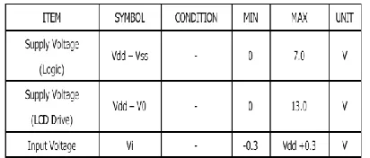
A liquid crystal display is a thin, flat display device made up of any number of color or monochrome pixels arrayed in front of a light source or reflector. Each pixel consists of a column of liquid crystal molecules suspended between two transparent electrodes, and two polarizing filters, the axes of polarity of which are perpendicular to each other. Without the liquid crystals between them, light passing through one would be blocked by the other. The liquid crystal twists the polarization of light entering one filter to allow it to pass through the other. Here we are using 16x2 LCD it displays 16 letters in 2 lines.
Table -1: absolute maximum rating of an LCD
Available Online at www.ijpret.com 254
caution like some work is going on or some problem occurred at that distance. It may be designed to send the speed to be maintained according to the problem complexity.
By using Kiel software writing a program with a c compiler as per the PIC instruction set and program is written to compare the values it consists and display it on LCD. When emergency caution is received by the RF receiver then automatically those instructions are given higher priority and displayed on the LCD display. Some additional alerting systems could also be excited by the microcontroller in order to alert the loco pilot. They may be buzzers, flashing lights likewise.
Fig.4: Kiel software for programming the microcontroller.
5. RESULTS
Available Online at www.ijpret.com 255
When the emergency caution is received by the RF receiver then the higher priority is given to that emergency caution order and displays the follow able speed. Driver is alerted by means of alerting mechanisms like buzzing and flashing lights.
Fig5: Digital caution board in loco hardware implementation.
Fig5: caution board specifying speeds to be maintained.
Available Online at www.ijpret.com 256 6. CONCLUSION
The digital caution board provides the prominent replacement of traditional caution paper and red flags.
Caution board enables safe journey in case or some climatic calamities like haze, fog etcetera. Ensures safe and in-time journey between the two stations. Avoids unexpected accidents and derailing due to misleading the speeds at restricted areas. In future these caution boards can be interfaced to the automated systems like self breaking system, automatic speed control systems and automatic track stability detectors etc.
7. REFERENCES
1. www.labcenter.com.
2. www.keil.com.
3. www.ikalogic.com
4. Microcontroller and embedded systems, Pearson Education inc. 2ndedition .
5. www.alldatasheets.com.
6. Diesel loco shed south central railways Vijayawada.