Volume 66, 2019, Pages 1–10
Proceedings of 6th International OM-NeT++ Community Summit 2019
Evaluating Modern Data Centre Transport Protocols in
OMNeT++/INET
Mohammed Alasmar and George Parisis
School of Engineering and Informatics University of Sussex, UK
[email protected],[email protected]
Abstract
In this paper we present our work towards an evaluation platform for data centre transport protocols. We developed a simulation model for NDP1, a modern data transport protocol in data centres, a FatTree network topology and per-packet ECMP load balancing. We also developed a data centre environment that can be used to evaluate and compare data transport protocols, usch as NDP and TCP. We describe how we integrated our model with the INET Framework and present example simulations to showcase the workings of the developed framework. For that, we ran a comprehensive set of experiments and studied different components and parameters of the developed models.
1
Introduction
The study of network protocols for Data Centre Networks (DCNs) has become increasingly important, given that data centres support all major Internet services, such as search (e.g. Google), social networking (e.g. Facebook), cloud services (e.g. Amazon EC2) and video streaming (e.g. NetFlix). DCNs consist of a large number of commodity servers and switches and support multiple paths among servers. Recent research on data centre networking is based on various simulation tools and respective models for network protocols [16,20,19].
OMNeT++ [26] is an excellent candidate for developing models for data centre networks and respective protocols, and more work is required for establishing it as the de facto simulator for this research community. This is possible through the INET Framework, which is built on top of the simulation core provided by OMNeT++. Omnet++ and INET is built around the concept of modules that communicate by message passing. Protocols are represented by components, which can be combined to form hosts, routers, switches and other networking devices. What makes this framework ideal for evaluating DCN protocols is that new modules can be easily integrated with the existing modules. DCN topologies (e.g. FatTree [1]) can be easily built and parameterised using Omnet++ NED language.
Modelling DCN protocols in OMNeT++. Recently, some DCN-related research has been based on OMNeT++/INET [21,5,11,3,4]. Achieving the critical mass of researchers that use OMNeT++ for evaluating data centre networks and protocols requires making more modern
protocols available in the OMNeT++ environment. Large-scale simulations are crucial for the DCN research community given that access to real-world deployments is very difficult. Devel-oping models for DCNs in OMNeT++ would also ensure reproducibility, revisability (dynamic debugging and profiling) and control over the studied traffic workloads (generating realistic traffic workloads in a deterministic fashion) [25].
Efficient data centre transport protocols. In DCNs, an efficient data transport mechanism is crucial to provide near-optimal completion times for short transfers and high goodput for long flows. The performance of TCP in DCNs is problematic due to TCP Incast [10], queue build-up and buffer pressure [14,24,17] and per-flow ECMP collisions. TCP performance can get singificantly degraded because of frequent retransmissions of lost packets [6,17]. Recently, a large body of work aimed at tackling various aspects of data centre transport: proposed approaches usually focus on either achieving low latency [6, 22, 27, 21, 7] or high throughput [17, 23, 12, 2]. NDP [14] appears to perform well with respect to both low latency and high throughput requirements by combining a number of data transport mechanisms.
NDP and FatTree models. In this paper we present an OMNeT++/INET framework for evaluating data transport protocols (NDP and TCP) in data centres. This includes: (1) a model for building FatTree topologies to evaluate the performance of TCP, NDP and other community-developed protocol models for data centres (§2), (2) a model for packet and per-flow Equal-Cost Multi-Path (ECMP) load balancing in a FatTree topology (§3), (3) a model for NDP (§4 and §5), and (4) a central traffic scheduler for scheduling flows in the simulated network and setting up simulation parameters for experimenting with the above-mentioned contributions (§5).
2
FatTree Topology
Among the recently proposed DCN topologies, FatTree, which originated from the Clos switch-ing network, is widely used [1]. We developed a FatTree topology generator using the NED language. FatTree data centres allow any two servers to communicate by fully utilising network resources and ensuring non-blocking behaviour. The role of core switches is to forward traffic among aggregation switches, and that of the aggregation switch is to inter-connect core and edge switches. The edge switches reside at lowest level of the topology, and forward traffic between hosts and aggregation switches (see Figures 1a&2). The size of a FatTree topology depends on the number of pods it consists of (k). A FatTree network consists of three layers: the core layer, aggregation layer and edge layer. In a k-ary FatTree topology there are k2/4 core switches which is the same number as the shortest-paths between any two servers that are connected to any pod in the network. Each pod containsk servers andk switches. These switches are divided into two layers each consisting ofk/2 switches. The first layer is the edge where each switch is connected tok/2 of the servers (a rack) in the same pod, while the second layer is the aggregation layer where each switch is connected tok/2 of the core switches. Each core switch is connected to one aggregation switch of each pod. The maximum number of servers in a FatTree withkpods isk3/4. All switches have the same number of ports which is
equal tok. Table 1summarises the construction of ak-ary FatTree (with examples whenk= 4, 8 and 10).
Pods k 4 8 10
Servers k×k/2×k/2 16 128 250
Core switches (= servers in each Pod) k/2×k/2 4 16 25
Edge switches in each Pod (racks) k/2 2 4 5
Aggregation switches in each Pod k/2 2 4 5
Total edge/aggregation switches k×k/2 8 24 50
Switch ports k 4 8 10
Equal-cost path between any pair of
servers (at different pod) k/2×k/2 4 16 50
Table 1: k-ary FatTree topology architecture: examples whenk= 4, 8 and 10
(a) FatTree (b) Pod
(c) Rack
networkFatTreeNdp {
parameters:
// k pods intk = default(4);
submodules: Pod[k]: Pod;
CoreRouter[(k/2)^2]: Router;
connections:
fori=0..k-1, forj=0..sizeof(CoreRouter)-1{
Pod[i].podg++ <-->CoreRouter[j].pppg++;
} }
(a) FatTree topology (k=4)
[General] network= FatTreeNdp **.k = ${FatTreeSize=4..40step2} **.trafficMatrixType = ${"permTM"}
# or randTM
**.arrivalRate =2000 #Poisson process
**.flowSize =100# 150KB(each 1500B)
**.numShortFlows = 2000 **.longFlowSize =100000#150MB
**.percentLongFlowNodes =0.15 **.initialWindow =15 **.ndpSwitchQueueLength =8 **.perPacketEcmp =true
**.perFlowEcmp =false
**.seedValue =1111 **.ppp[*].queueType ="NDPQueue”
(b) centralScheduler ini file
Figure 1: FatTree implementation in NED language including a central scheduler node
Core
1
Agg.
Edge
path1
path2
path3
path4
Hostx Hosty
Hosta Hostb
(a) Per-flow ECMP (b) Per-packet ECMP
Figure 2: (a) Per-flow ECMP vs (b) per-packet ECMP in 4-FatTree Figure 3: NDP modules
3
Per-packet and per-flow ECMP
order to their destination. However, this can cause significant underutilisation in the network due to collisions of large flows (i.e. when a large number of flows cross the same link while other links are not used) and this can significantly reduce throughput, as discussed in [13]. In addition, per-flow load-balancing can result in unequal link utilisation and hotspots. In per-packet ECMP, packet forwarding is randomised over all equal-cost links used for load balancing, as shown in Figure2b. Per-packet multipath forwarding is a good option when using a data transport protocol that can tolerate reordering (e.g., NDP [14][3]). As per-packet ECMP may result in packets arriving out of order, it cannot be used with data transport protocols that are sensitive to packet reordering (e.g., TCP).
A model of per-packet and per-flow ECMP in INET. We implemented both per-packet and per-flow ECMP by updating the source code that is provided in INETv3.6.3 network layer. Routing in INET is done in five main steps as follows: (1) building topology and assigning addresses (NetworkConfiguratorBase::Topology), (2) setting links and node weights
(IPv4NetworkConfigurator::computeConfiguration), (3) using Dijkstra’s Algorithm for
multi-ple paths (Topology::calculateWeightedSingleShortestPathsTo), (4) adding a route to all des-tinations in the network (IPv4NetworkConfigurator::addStaticRoutes) and (5) generating the routing tables (IPv4RoutingTable::printRoutingTable).
When implementing ECMP, we updated step 3 so that all shortest paths to all destinations are registered. Additionally, we updated step 4 to include the updates in step 3 when adding routes to all destinations. The routing tables in step 5 are automatically updated. Finally, we implemented the hashing function inIPv4RoutingTable::findBestMatchingRouteEcmp(which is called byIPv4::routeUnicastPacket). There are two options for hashing:
• per-packet ECMP:selectPath = rand()% numPossibleEcmpRouts, and
• per-flow ECMP:selectPath = hashValue% numPossibleEcmpRouts, where thehashValue
is calculated based on the 5-tuple (we also included the router’s name in this hashing).
4
A model of NDP in INET
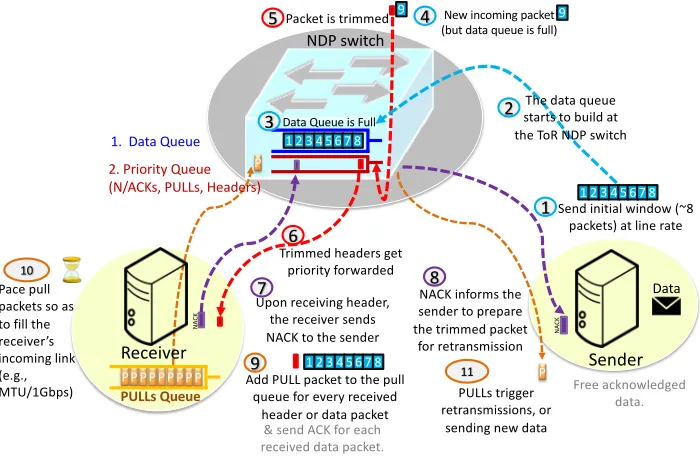
NDP aims at offering both low latency and high throughput in FatTree data centre networks. NDP combines several ideas into a clean slate protocol design. NDP exhibits very good perfor-mance by employing receiver-driven flow control and packet trimming. NDP will be deployable when P4 switches [9] are deployed in data centres. NDP operation can be summarised as follows (and depicted through the numbered circles in Figure4). Senders are allowed to send an initial window of data at line rate (circles 1 and 2). Switches use shallow buffers (e.g. 8 packets long) with two queues: the data (used for data packets only) and control (high priority) queue (for PULL, ACK, NACK and Header packets). If the data queue overflows, the packet payload is trimmed and the header is priority-forwarded (circles 3, 4, 5 and 6). At the receiver, an ACK for each data packet received and a NACK for each header will be sent immediately to the sender (circles 7 and 8). The receiver has a shared PULL queue between all active connections. The receiver adds a PULL packet for every received header or data packet (circle 9). The receiver paces PULL packets so as to fill the receiver’s incoming link. Pacing is across all connections, so that the aggregate rate matches the receiver’s link speed (circle 10). The goal is to keep the incoming link full, so the receiver spaces pull requests accordingly (e.g. assuming each incoming packet has the same MTU size = 1500B, then the receiver sends a packet every 1M T UGbps = 12µ
1 2 3 4 5 6 7 8
Data Queue is Full
New incoming packet (but data queue is full)
Packet is trimmed
Upon receiving header, the receiver sends NACK to the sender
Sender
PULLs Queue
NA
CK
NA
CK
NACK informs the sender to prepare the trimmed packet
for retransmission
Add PULL packet to the pull queue for every received
header or data packet P
P
P PULLs trigger retransmissions, or
sending new data
Data
1 Send initial window (~8
packets) at line rate
2 NDP switch
1. Data Queue
2. Priority Queue (N/ACKs, PULLs, Headers)
3
4
1 2 3 4 5 6 7 8 9
5
6
7 8
9 1 2 3 4 5 6 7 8
P P P P P P P P Pace pull
packets so as to fill the receiver’s incoming link (e.g., MTU/1Gbps)
10
11
The data queue starts to build at the ToR NDP switch
Trimmed headers get priority forwarded
Receiver
9
& send ACK for each received data packet.
Free acknowledged data.
Figure 4: NDP operation2
seconds if the receiver’s link speed is 1Gbps). At the sender, PULL requests trigger either a retransmission or a new data packet (circle 11).
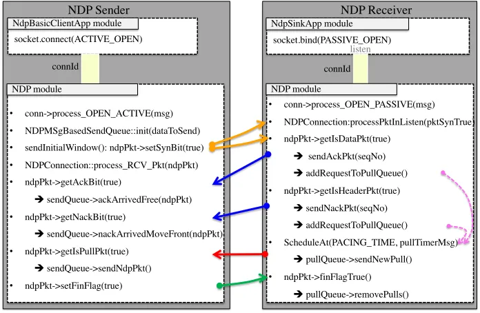
Here we describe how we implemented NDP in INET. Our implementation follows the TCP model in INET. We developed StandardHostNdp, a predefined NED type which is an OM-NeT++ compound module that is composed of the following components:
Applications. There are two main applications that can communicate with the NDP layer, as shown in Figure3. The first application is theNdpBasicClientApp module, which is used by NDP senders to start a connection. The second application module isNdpSinkApp which is used by NDP receivers to listen for incoming connections. NDP applications and the NDP layer communicate with each other by sendingcMessageobjects. These messages are specified in the NDPCommand.msg file. The NDPCommandCode enumeration defines the types of messages that are sent by the application to the NDP layer. These are the main message types:
NDP C OPEN ACTIVE: active open,NDP C OPEN PASSIVE: passive open,NDP C SEND:
send data and NDP C CLOSE: no more data to send. Each command message should have attached control information of type NDPCommand. For example, the command message
NDP C OPEN ACTIVE requires this control information to be attached: connId, localAddr,
locarPrt,remoteAddr, remotePrt andnumPacketsToSend. In Figure5,NdpSinkApp can open
a local port by sending aNDP C PASSIVE OPEN to the NDP layer with control information that contains the local address and port. NdpBasicClientApp opens a connection to a remote server by sending aNDP C OPEN ACTIVE command to the NDP layer.
socket.connect(ACTIVE_OPEN)
connId
NDP Sender NDP Receiver
connId NdpBasicClientApp module
NDP module
• conn->process_OPEN_ACTIVE(msg)
• NDPMSgBasedSendQueue::init(dataToSend)
• sendInitialWindow(): ndpPkt->setSynBit(true)
• NDPConnection::process_RCV_Pkt(ndpPkt)
• ndpPkt->getAckBit(true)
èsendQueue->ackArrivedFree(ndpPkt)
• ndpPkt->getNackBit(true)
èsendQueue->nackArrivedMoveFront(ndpPkt)
• ndpPkt->getIsPullPkt(true)
èsendQueue->sendNdpPkt()
• ndpPkt->setFinFlag(true)
• conn->process_OPEN_PASSIVE(msg)
• NDPConnection:processPktInListen(pktSynTrue)
• ndpPkt->getIsDataPkt(true)
èsendAckPkt(seqNo)
èaddRequestToPullQueue()
• ndpPkt->getIsHeaderPkt(true)
èsendNackPkt(seqNo)
èaddRequestToPullQueue()
• ScheduleAt(PACING_TIME, pullTimerMsg)
èpullQueue->sendNewPull()
• ndpPkt->finFlagTrue()
èpullQueue->removePulls() NDP module
NdpSinkApp module socket.bind(PASSIVE_OPEN)
listen
Figure 5: NDP implementation
NDP I DATA: data packet received andNDP I PEER CLOSED: FIN flag received from remote
NDP. The NDP module and the NDP applications implement NDP operations (as discussed in
§4) as follows:
1. The NDP sender performs the following operations (see Figure5):
• creates the sendQueue for the data to be sent: NDPMSgBasedSendQueue::init(data),
• sends the initial window of data packets with SYN flag: sendInitialWindow(),
• precesses received packet (can be ACK, NACK or PULL) from the receiver:
NDPCon-nection::process RCV Pkt(ndpPkt). The sender takes one of the following actions:
– frees acknowledged data packet: sendQueue->ackArrivedFree(ndpPkt),
– queues NACKed data packet for retransmission: nackArrivedMoveFront(ndpPkt),
– sends data packet if PULL request arrived: sendQueue->sendNdpPkt(),
• sets the FIN flag when sending the last data packet: ndpPkt->setFinFlag(true).
2. The NDP receiver performs the following operations (see Figure5):
• establishes a connection when receiving a data packet with the SYN flag set:
NDPCon-nection:processPktInListen(pktSynTrue),
• acknowledges a received data packet: sendAckPkt(seqNo),
• sends NACK when receiving header packet: sendAckPkt(seqNo),
• adds PULL packet to the PULL queue upon receiving either data or header packet:
addRequestToPullQueue(),
• schedules a self message that is used to pace pull packets from the PULL queue: Sched-uleAt(PACING TIME, pullTimerMsg)
• removes all pull packets when receiving the last data packet: pullQueue->removePulls()
as discussed in§3.
NICs. We use the available NIC modules (PPPInterface and EthernetInterface) that are provided in the INET Framework.
NDP Switch. It contains two queues: (1) highPriorityQueue: which is used to enqueue Header, ACK, NACK and PULL packets, and (2)dataQueue: which is used to enqueue data packets. NDP switches trim packets when theirdataQueue is full and insert the headers in the
highPriorityQueue. NDPSwitch:dequeue() is round robin (10:1 ratio) between the two queues.
5
Experimenting with the Simulation Framework
We developed a central scheduler node (centralSchedulerNdp3) to schedule NDP connections in a FatTree topology (as shown in Figure1). The main parameters in this node are shown in Figure1b and explained below:
• FatTreeSize. This is used to generate ak-ary FatTree topology (as described in§2)
• trafficMatrixType. The scheduler node can schedule either a permutation or random traffic
matrix (as explained in[18])
• arrivalRate. This is used to generate flow arrival times according to a Poisson process.
This is implemented by creating an exponential distribution (mean = 1/λ) based on the Poisson arrival rateλ.
• flowSize. This is the size of the data (number of packets) that each created
NdpBasic-ClientApp is going to send to anNdpSinkApp.
• numShortFlows. This is the number of NDP connections that will be scheduled based on
the selected traffic matrix, e.g. scheduling 1000 flows means that there are 1000 different
NdpBasicClientApps communicate with 1000NdpSinkApps.
• longFlowSize and percentLongFlowNodes. These parameters are used to generate
back-ground traffic in the simulation. The backback-ground traffic can either run until all short flows will finish or by assigning the size of the long flows to a large flow size. For example,
percentLongFlowNodes of 30% in a 10-FatTree (250 servers) topology means that there
are 75 servers that are used only to run background traffic.
• initialWindowandndpSwitchQueueLength. These are used as described in Section
refndp-section).
5.1
NDP Experiments
Here, we present experimentation using the developed NDP model. We conducted four different experiments4.
Experiment 1. We ran this experiment with the parameters that are shown in Figure1b in a 6-FatTree (54 servers) where 15% of servers (8 servers) ran background load. The number of short flows were 2000 and each flow had a size of 150KB. The results of this experiment are shown in Figure6(one seed was used). The developed model provides the ability to record and plot the following measurements: goodput (Figure 6a), flow completion time (FCT) (Figure 6b), the number of received header packets per flow (connection) (Figure6c), the number of data sending applications at each server (Figure6d), the number of data receiving applications at each server (Figure6d) and traffic matrix plot (Figure6e). We use OMNeT++’sscavetool command-line
3We have developed another scheduler:centralSchedulerTcp, which is used for TCP experiments and it has
a similar interface as the NDP scheduler. It is used to schedule TCP connections in a FatTree topology.
4Due to space limitations we will not discuss simulations with TCP. Some of these results can be found
500100015002000 Rank of trasnport flow 0 0.2 0.4 0.6 0.8 1 Goodput (Gbps) 150KB
Rank of transport flow
(a) Goodput
1 2 3 4
FCT (msec) 0 0.2 0.4 0.6 0.8 1 CDF 150KB (b) FCT 0 2 4 6 #received headers
1950 1960 1970 1980 1990 2000 Rank of short flow
(c) Num. of received headers
0 20 40 60
#NdpBasicClientApp
11121314151
Servers
ShortFlow NodeLongFlow Node
(d) #created sender’s app.
0 20 40 60
#NdpSinkApp
11121314151 Servers ShortFlow NodeLongFlow Node
(e) #created receiver’s app.
0 5 10 15 20 25 30 35 40 45 50 Source Server 5 10 15 20 25 30 35 40 45 50 55 60
Destination Server 36 41 43 50 54 43 46 47 44 4155 40 37 51 42 34 45 45 38 46 46 39 46 39 41 4741 50 34 34 51 38 45 40 49 47 41 52 34 36 48 53 46 43 54 28 LongFlowsShortFlows
(f) Perm. traffic matrix
Figure 6: The results of running 2000 NDP short flows (150KB each) in a 6-FatTree (54 servers)
1 6 11 16 21 26 31 36 Core Swithces 0 20 40 60 80 #Received Packets 103 Core switches
(a) Per-flow ECMP
1 6 11 16 21 26 31 36
Core Swithces 0 20 40 60 80 #Received Packets 103 Core switches
(b) Per-packet ECMP
Figure 7: Per-flow vs per-packet ECMP in 12-FatTree (36 core switches) topology. Each colour in each bar (12 colours) represents the number of received packets at each port (12-port switch)
tool to process the results. These scripts can be found in the shell file (runNdpSimulation.sh) that we use to run the simulation and generate several.csv files which are input to MATLAB scripts to produce the required figures5. The results are as expected; most flows achievedvery high goodput and low Flow Completion Times.
Experiment 2. In this experiment, we compare between per-flow and per-packet ECMP in a FatTree topology. We have simulated the two protocols in a 12-FatTree (36 core switches) by running 5000 short flows (300KB each) and with arrival rateλ = 2000 (without introducing any background load). The other parameters are as depicted in Figure1b. Figure7illustrates the number of received packets at each port of the 36 12-port core switches. It is obvious that per-packet ECMP provides better load balancing than per-flow ECMP (as discussed in§3).
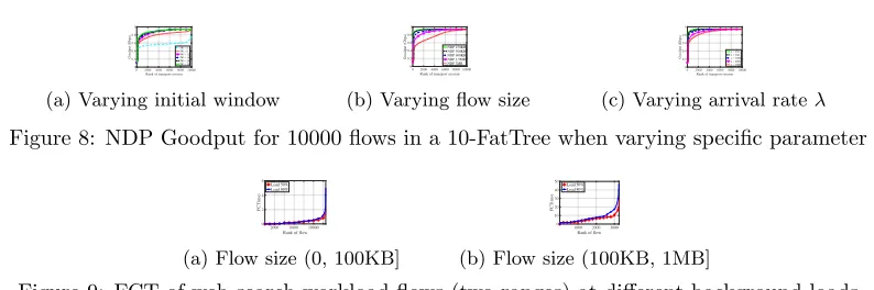
Experiment 3. In this experiment we test the performance of NDP when varying specific parameters. A key parameter of NDP is the initial window of packets that a sender pushes to the network. In Figure8a, we observe that for very small values of the initial window, the goodput is very low and the receiver’s downlink underutilised. As the window increases, utili-sation approaches the maximum available link capacity (for 16 packets). For larger values, the measured goodput is the same (full link capacity). In Figure8b, we show the goodput of NDP flows at different flow sizes (whenλ= 2500). Similarly, in Figure8b, we obtain the goodput of 10000 flows (1.5MB each) at differentλvalues.
Experiment 4. In the experiment, we use realistic web search workloads reported by data centre operators to evaluate NDP [6]. We simulate two target loads of background traffic (0.5 and 0.8). We generate 20000 flows, withλ= 2500. We report the flow completion time (FCT) of all flows (split in two different ranges), as shown in Figure9. NDP achieves low FCT.
6
Summary and future work
The proposed model is intended to be used to evaluate NDP and compare its performance with existing models (e.g. TCP) in a FatTree data centre topology. The current
0200040006000800010000 Rank of transport session 0 0.2 0.4 0.6 0.8 1 Goodput (Gbps)
IW = 4 IW = 8 IW = 12 IW = 16 IW = 20 IW = 24
(a) Varying initial window
02000400060008000 10000 Rank of transport session 0 0.2 0.4 0.6 0.8 1 Goodput (Gbps) NDP 150KB NDP 300KB NDP 900KB NDP 1.5MB NDP 3MB
(b) Varying flow size
0200040006000800010000 Rank of transport session 0 0.2 0.4 0.6 0.8 1 Goodput (Gbps) = 250 = 500 = 1000 = 2000 = 3000
(c) Varying arrival rateλ
Figure 8: NDP Goodput for 10000 flows in a 10-FatTree when varying specific parameter
2000 6000 10000 Rank of flow 0 2 4 6 FCT(ms) Load 50% Load 80%
(a) Flow size (0, 100KB]
1000 2000 3000
Rank of flow
0 10 20 30 40 50 FCT(ms) Load 50% Load 80%
(b) Flow size (100KB, 1MB]
Figure 9: FCT of web search workload flows (two ranges) at different background loads
tion supports most of NDP’s specifications. The current version of our NDP model does not support priority pulling at the pull queue. As a future work, we plan to improve the NDP model by allowing priority pacing in the pull queue for short flows. In addition, we aim at leveraging multiple priority queues available in commodity switches to implement a Multiple Level Feedback Queue (MLFQ). Also, we aim at evaluating NDP in Incast and Outcast sce-narios and assess the provided fairness among competing flows. Furthermore, we plan to build more OMNeT++/INET-based models that simulate other modern data transport protocols for DCNs, such as DCTCP[6], MPTCP[24], DCQCN[28] and PIAS[8].
References
[1] Mohammad Al-Fares, Alexander Loukissas, and Amin Vahdat. A scalable, commodity data center network architecture. InProc. of SIGCOMM, 2008.
[2] Mohammad Al-Fares, Sivasankar Radhakrishnan, Barath Raghavan, Nelson Huang, and Amin Vahdat. Hedera: Dynamic Flow Scheduling for Data Center Networks. In Proc. of USENIX, 2010.
[3] Mohammed Alasmar, George Parisis, and Jon Crowcroft. Polyraptor: Embracing path and data redundancy in data centres for efficient data transport. InProceedings of the ACM SIGCOMM
2018 Conference on Posters and Demos, 2018.
[4] Mohammed Alasmar, George Parisis, and Jon Crowcroft. SCDP: Systematic Rateless Coding for Efficient Data Transport in Data Centres. Inhttp://arxiv.org/abs/1909.08928, 2019.
[5] M. Alizadeh, B. Atikoglu, A. Kabbani, A. Lakshmikantha, R. Pan, B. Prabhakar, and M. Seaman. Data center transport mechanisms: Congestion control theory and ieee standardization. InAnnual
Allerton Conference on Communication, Control, and Computing, 2008.
[6] M Alizadeh, Albert Greenberg, David A Maltz, Jitendra Padhye, Parveen Patel, Balaji Prabhakar, Sudipta Sengupta, and Murari Sridharan. Data Center TCP (DCTCP). InSIGCOMM, 2010. [7] Mohammad Alizadeh, S Yang, Milad Sharif, Sachin Katti, Nick McKeown, Balaji Prabhakar, and
Scott Shenker. pfabric: Minimal near-optimal datacenter transport. InProc. of SIGCOMM, 2013. [8] Wei Bai, Li Chen, Kai Chen, Dongsu Han, Chen Tian, and Hao Wang. Information-agnostic flow
scheduling for commodity data centers. InIn Proc. NSDI, USENIX, 2015.
[9] Pat Bosshart, Dan Daly, Glen Gibb, Martin Izzard, Nick McKeown, Jennifer Rexford, Cole Schlesinger, Dan Talayco, Amin Vahdat, George Varghese, and David Walker. P4: Program-ming protocol-independent packet processors. InACM SIGCOMM, 2014.
[11] T. Das and K. M. Sivalingam. Tcp improvements for data center networks. In2013 Fifth
Inter-national Conference on Communication Systems and Networks (COMSNETS), 2013.
[12] A Dixit, P Prakash, Y C Hu, and R R Kompella. On the impact of packet spraying in data center networks. InProc. of INFOCOM, 2013.
[13] Chuanxiong Guo, Haitao Wu, Zhong Deng, Gaurav Soni, Jianxi Ye, Jitu Padhye, and Marina Lipshteyn. Rdma over commodity ethernet at scale. InSIGCOMM, 2016.
[14] Mark Handley, Costin Raiciu, Alexandru Agache, Andrei Voinescu, Andrew W. Moore, Gianni Antichi, and Marcin W´ojcik. Re-architecting datacenter networks and stacks for low latency and high performance. InProc. of SIGCOMM, 2017.
[15] C. Hopps. Analysis of an Equal-Cost Multi-Path Algorithm Status. IETF, RFC 2992, 2000. [16] Teerawat Issariyakul and Ekram Hossain. Introduction to Network Simulator NS2. Springer
Publishing Company, Incorporated, 2010.
[17] M. Kheirkhah, I. Wakeman, and G. Parisis. MMPTCP: A multipath transport protocol for data centers. InProc. of INFOCOM 2016, 2016.
[18] Morteza Kheirkhah. Mmptcp: a novel transport protocol for data centre networks[. InUniversity
of Sussex, 2016.
[19] Morteza Kheirkhah, Ian Wakeman, and George Parisis. Multipath-TCP in ns-3. InWNS3, 2014. [20] A. R. A. Kumar, S. V. Rao, and D. Goswami. Ns3 simulator for a study of data center networks.
InIEEE International Symposium on Parallel and Distributed Computing, 2013.
[21] Behnam Montazeri, Yilong Li, Mohammad Alizadeh, and John Ousterhout. Homa: A receiver-driven low-latency transport protocol using network priorities. In In Proc. ACM SIGCOMM, 2018.
[22] A. Munir, I. A. Qazi, Z. A. Uzmi, A. Mushtaq, S. N. Ismail, M. S. Iqbal, and B. Khan. Minimizing flow completion times in data centers. InIEEE INFOCOM, 2013.
[23] Costin Raiciu, Sebastien Barre, Chris Pluntke, Adam Green, Damon Wischik, and Mark Handley. Improving Datacenter Performance and Robustness with Multipath TCP. InSIGCOMM, 2011. [24] Costin Raiciu, Christopher Pluntke, Sebastien Barre, Adam Greenhalgh, Damon Wischik, and
Mark Handley. Data Center Networking with Multipath TCP. InProc. of SIGCOMM. ACM, 2010.
[25] Bilel Ben Romdhanne. Large-scale network simulation over heterogeneous computing architecture.
InTelecom ParisTech, 2013.
[26] A. Varga. Omnet++ discrete event simulation. InSystem User Manual, 2006.
[27] H. Xu and B. Li. Repflow: Minimizing flow completion times with replicated flows in data centers.
InIEEE INFOCOM, 2014.